|
|

This chapter describes the FastPADmp12 front panel, rear panel, and processor board.
The FastPADmp12 is a stand-alone product providing 12 lines, just like the mp, but is a more powerful device. When the mp12 is rack-mounted, it functions as one logical unit providing 36 ports.
The FastPAD mp12 can provide 12 lines (L0-L11) or 36 lines (L0-L35). It can handle speeds up to E1.
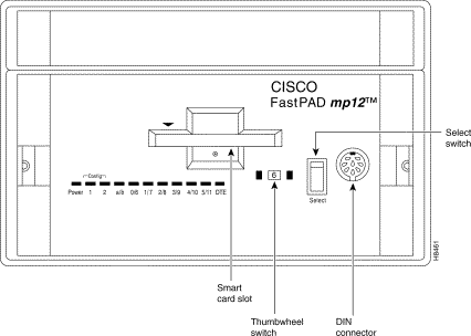
Figure 3-1 shows the FastPADmp12 front panel. The front panel is similar to the mp's front panel. Refer to the section "FastPADmp Front Panel" in the chapter "FastPADmp Hardware Description" for details.
The FastPADmp12, like the mp, is designed around a motherboard—MPB—and a daughterboard—MTB.
Figure 3-2 illustrates the MPB, MTB and jumper positions.
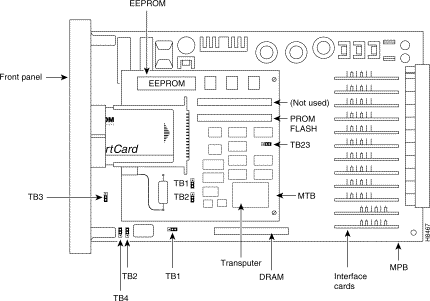
The meaning on the jumpers on the MPB is the same as for the mp. (See Table 3-1.)
| Jumper | Default setting |
|---|---|
TB1 | Position A (reserved) |
TB2 | Position NOT LWD (reserved) |
TB3 | Position NOT ABORT (reserved) |
TB4 | Authorizes a reset of hardware (Thumbwheel set to "F", front panel "Select" button depressed) |
The jumpers on the MTB are described in Table 3-2.
| Jumper | Meaning | Default setting | |
|---|---|---|---|
Reserved | TB1 | 1: Extension Transputer 2: Standard | 2 |
Reserved | TB2 | 1: Extension Transputer 2: Standard | 2 |
Reserved | TB23 | 1: 25 MHz 2: 16 MHz | 1 |
This section describes the FastPADmp12 rear panel connectors and power supply.
The FastPAD mp12 rear panel or ViB12T board has 12 DB-25 female connectors for 12 lines numbered from L0-L11.
Figure 3-3 illustrates the ViB12T.
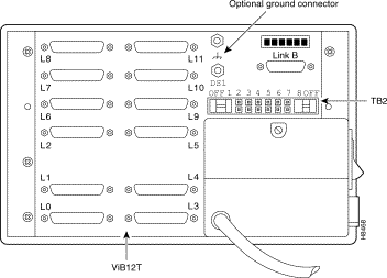
On the rear panel, blue jumpers refer to TB2. For a stand-alone mp12, these jumpers are illustrated in Figure 3-4.

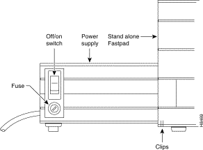
All stand-alone FastPADmp12 devices include a power supply on the rear panel of the module. Stand-alone power supplies have an on/off switch and a fuse. Rack-mounted models receive power from a power supply built into the rack.
The power supply is attached to the ViB12T board by a screw (see Figure 3-3) and two clips (see Figure 3-5). See the appendix "Specifications" for specifications.
This procedure is the same as for an mp. Refer to the section "Installation" in the chapter "FastPADmp Hardware Description."
Modules are interconnected using link connector A and B on the ViB12T board. The link between modules is called an Inter-Module Link (IML). IMLs are high-speed links (20 Mb/s) managed by transputer.
Figure 3-6 illustrates the rear of a unit.
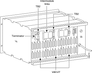
The shelf is shipped with the rear panel already attached. The rear panel is composed of three ViB12T boards interconnected with the IML connector, already attached. It provides 36 physical ports.
In front of the rear panel, from the right to the left, there are: Module 0, Module 1,
Module 2. Link A, on each ViB12T is now available, since there is no more power supply connected.
 | Warning Never remove the IML Connector while the unit is powered up. |
The TB2 jumper settings in Module 0 are shown in Figure 3-7.

The M1 and M2 jumper settings are the same as for a stand-alone (see Figure 3-8).

A unit based on three FastPAD mp12 provides 36 ports (3x12). As the rear panel is based on the ViB12T, lines are numbered from L0-L11, modulo 12.
For example:
Line 12 is line 0 of Module 1
Line 15 is line 3 of Module 1
Line 24 is line 0 on Module 2
First, install the shelf (see the chapter "Overview"). Take the following steps to check power compatibility:
Step 2 Check the IML connection and TB2 Jumper position.
Step 3 Insert the SmartCard in the front panel opening of the module.
Step 4 Set the Interface Card according to your needs. (See the chapter "Interface Cards.")
Step 5 Insert the module in the rack.
Step 6 Wait for the autotest, approximately two minutes.
Step 7 The equipment is operational and in default configuration (see Table 3-3).
| Power | 1 | 2 |
|---|---|---|
Green | Orange | Green |
Step 8 Connect a terminal on the front panel (OPALE) or on port 5 (modulo 12) to access the configuration function. Refer to the FastPAD Configuration Manual for more details.
![]()
![]()
![]()
![]()
![]()
![]()
![]()
![]()
Posted: Thu Jan 25 13:33:20 PST 2001
All contents are Copyright © 1992--2001 Cisco Systems, Inc. All rights reserved.
Important Notices and Privacy Statement.