|
|

This chapter describes the FastPADmp6 front panel, processor board, and rear panel. The FastPADmp6 is the smallest of the multiprotocol products, designed for branch office applications.
This chapter includes the following sections:
The FastPADmp6 is designed around a Single Processor Board (SPB). The front panel and the rear panel of the FastPADmp6 are attached to the SPB. (See Figure 5-1.)
The FastPADmp6 provides six lines (L0-L5):
The FastPADmp6 handles lines up to 1Mb/s if DCE on lines L0, L1, and L3 and accepts T1 if DTE on line L0, L1, and L3.
The front panel of the mp6 is specific to the mp6 alone.
Figure 5-2 shows the FastPADmp6 front panel. The LEDs are described in Table 5-1.
During normal operation, front panel LEDs are as described in Table 5-1.
| LED | State | Indication |
|---|---|---|
Power | Off Green Red
| Unit is powered off. FastPAD is powered on and operational. FastPAD is powered on, in test phase, or indicates a problem. Boot status or downloading the operational program. |
CONFIG (yellow) | Off On Flashing | Default Configuration (DEF) is selected. User Configuration (USR) is selected. Autotest (TST). |
The thumbwheel switch is equipped with two buttons that rotate the switch. The switch selection is displayed in the window between the buttons. (See Table 5-2.)
| Display | Selects | mp, mp12, mpr Equivalent |
|---|---|---|
0 | Operational configuration and software—downloading of software possible. Display of CPU load. |
|
1 | Default configuration and operational software. | E + 10 |
2 | Operational configuration and software. | E + 11 |
3 | Copy default configuration to operational configuration and start-up with operational configuration and software. | E + 8 |
4 | Boot (reserved). | E + C |
5-9 | Downloading of operational configuration and software. |
|
 | Warning The thumbwheel position is taken into account after the autotest, and when you exit from the configuration function. |
The front panel DIN connector has the same function on the FastPADmp6 as it does on the other FastPAD products. Refer to the section "DIN Connector" in the chapter ""Overview" for details.
The FastPADmp6 processor board consists of a main card with two MC 68302 (L0) microprocessors, AC to DC conversion circuitry, and one slot for an interface card, jumpers, termination (Jxx), two slots for Flash SIMMs, and one slot for a DRAM SIMM.
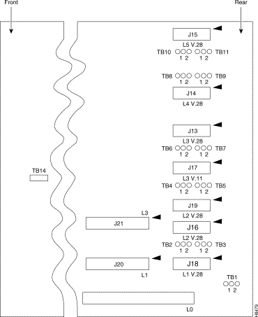
Figure 5-3 illustrates the location of the different terminations and jumpers on the FastPADmp6 processor board.

The processor board is attached to the front panel. Take the following steps to remove the processor board:
Step 2 With a blade screwdriver, rotate the two screws counterclockwise on the rear panel.
Step 3 Press the catches outward and pull the front panel forward.
To define the FLASH PROM used by the equipment, you can adjust the placement of TB14 as follows:
The following lines are on the SPB near the rear panel:
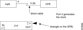
When you want to generate the clocking signal as a DCE, the terminal inscription OUT must be in front of the triangle on the SPB. (See Figure 5-4.)
When you want to receive the clocking signal as a DTE, the termination inscription IN must be in front of the triangle on the SPB. This role is performed by terminations J13, J14, J15, J16, J17, J18, J19. (See Figure 5-5.)

L1 and L3 can be set to work as V.28 or V.11. These two lines have another termination to determine the electrical interface type—J20 for line 1 and J21 for line 3. (See Figure 5-6 and Figure 5-7.)

Table 5-3 lists the different combinations for the different lines (L1-L5).
| Line1 | V.11 | V.28 |
|---|---|---|
1 | J20 and J16 | J20 and J18 |
2 | - | J19 |
3 | J21 and J17 | J21 and J13 |
4 | - | J14 |
5 | - | J15 |
For each line, jumpers define if the above ITU-T signals are controlled or not. Table 5-4 lists the different settings.
| L0 | L1 | L2 | L3 | L4 | L5 | Position |
|---|---|---|---|---|---|---|
See interface card | TB2 | TB4 | TB6 | TB7 | TB8 | 1=CT111 2=CT116 |
TB1 | TB3 | TB5 | TB7 | TB9 | TB11 | 1=CT117 2=CT125 |
This section describes the FastPADmp6 rear panel connectors and power supply.
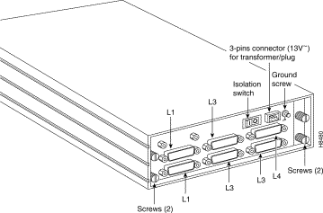
The FastPADmp6 has DB25 connectors for 6 lines (L0-L5), and an optional external ground connector. (See Figure 5-8.)

All stand-alone FastPADmp6 units include a transformer power unit which plugs into the rear panel of the unit. This transformer converts voltage down from 115V AC/60 Hz/200mA/23VA to 2 x 13V AC/650mA/17VA.
Step 2 Press the extractor outward.
Step 3 Pull out the SPB card (with the front and rear panel).
Step 4 Set the interface card (L0) termination and jumpers on the correct position.
Step 5 Plug in the SPB.
Step 6 Set the thumbwheel on the front panel at a position from 5 to 9.
Step 7 Screw the four screws on the rear panel.
Step 8 Plug in the transformer.
Step 9 Switch on the device.
Step 10 Wait for the autotests.
![]()
![]()
![]()
![]()
![]()
![]()
![]()
![]()
Posted: Thu Jan 25 13:35:53 PST 2001
All contents are Copyright © 1992--2001 Cisco Systems, Inc. All rights reserved.
Important Notices and Privacy Statement.