|
|

This chapter contains the following sections:
This chapter describes the interface cards used with FastPADs. The FastPADmp products use flexible interface cards that are inserted into slots on the motherboard (for the FastPADmp and mp12, and in the termination for Line 0 on the motherboard of the mp6) or YB board (for the FastPADmpr12/24) to change the electrical specifications of the port.
Each FastPAD line has an interface card associated with it. The following interfaces are available:
Figure 6-1 illustrates installing interface cards.
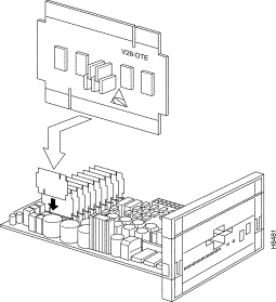
Each interface card can supply a DTE or DCE interface. DTE or DCE is selected by the way you insert the card into the slot. Figure 6-2 shows the V.28 interface card in both DTE and DCE orientations. The setting that is visible on the card after installing it in the board is the setting selected (either DTE or DCE).

The ISDN and G.703 interfaces are described later in this chapter.
In FastPAD default configuration, all 12 lines are equipped with the V.28 interface. Table 6-1 describes the cable and interface card combinations needed to construct various interfaces. Table 6-2 lists default line configurations.
| Interface | Interface card | Cables | Connectors |
|---|---|---|---|
V.24/V.28 V.35 X.21/V.11 X.21bis DTE X.21bis DCE | V28 V35 V11 V11 V11 | V28 V35 V11 X21bis DTE X21bis DCE | RS232m25/RS232m25 RS232m25/V35m34 RS232m25/DB15m15 RS232m25/RS449m37 RS232m25/RS449m37 |
| Line | Mode |
|---|---|
0, 1 | DTE |
2-11 | DCE |
5 | Async, 9600 bps, 8 data bits, no parity. Used for supervisory functions |
Lines L0 and L1 are in DTE mode. Lines L2-L11 are in DCE mode. Line 5 is configured as asynchronous, 9600 bps, 8/none, to provide access to the supervisory functions.
The V.28 interface card is equipped with six jumpers, as shown in Figure 6-3.
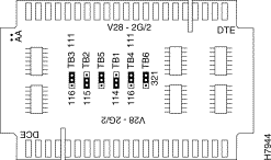
Table 6-3 lists jumpers and signals.
A jumper between pins two and three is written <2-3>.
A jumper between pins one and two is written <1-2>.
| Jumper | CCITT | Signal Name | Supplied |
|---|---|---|---|
TB1 | CT114 | Transmit clock | DCE |
TB2 | CT115 | Receive Clock | DCE |
TB3
| CT116 CT111 | Standby Data Rate Select | DTE DTE |
TB4 | CT116 | Standby | DTE |
| CT111 | Data Rate Select | DTE |
TB5 | CT113 | External Transmit Clock | Not used |
Used TB6 | N/A | Receive Clock Select Switch | N/A |
Connects or disconnects the Transmit Clock (CT114). Connecting the jumpers between pins 2 and 3 allows the device to operate in synchronous mode. Placing the jumper pins on 1 and 2 disconnects the signal, putting the interface into an asynchronous mode.
In DCE mode, the Transmit Clock is supplied by connecting the jumper between 2 and 3.
In DTE mode, the Transmit Clock is accepted by connecting the jumper between 2 and 3.
Connects or disconnects the Receive clock, CT115. Connecting the jumpers between pins 2 and 3 allows the device to operate in synchronous mode. Placing the jumper pins on 1 and 2 disconnects the signal, putting the interface into an asynchronous mode.
In DCE mode, the Receive Clock is supplied by connecting the jumper between 2 and 3.
In DTE mode, the Receive Clock is accepted by connecting the jumper between 2 and 3.
These jumpers choose between the use of two signals, either the Data Signal Rate Detector (CT111) or Standby Select (CT116).
The standby select signal is sent by a DTE (FastPAD) to a DCE (modem) to indicate that the DCE is allowed to initiate a backup in the event of a line failure. As far as the FastPADmp/PCS products are concerned, the function of Standby Select is used only with modems that recognize it, like the Philips Sematrans models. The Motorola Codex modems do not recognize this function.
The rate signal detect is issued by a DTE interface and instructs the communication device to use one of two pre-configured rates, a fast rate and slower rate. Again, this function is only relevant if both the DTE and DCE are configured to utilize this function. Generally, it won't often be used on FastPADmp/PCS connections.
Only one of the jumpers TB3 or TB4 is used in a DTE or DCE configuration. In a DTE configuration jumper TB3 is used. In a DCE configuration jumper TB4 is used. (See Table 6-4.)
| Mode | TB4 | TB3 |
DTE | Not used | Active |
DCE | Active | Not used |
We recommend that you set TB6 in the <1-2> position. This is the default setting.
The silk screen on the boards clearly indicates which jumper position selects the desired option. You can also use Table 6-5 as a reference.
| Jumper | <1-2> | <2-3> |
TB3 | Selects 111 | Selects 116 |
TB4 | Selects 111 | Selects 116 |
The most important thing to remember is that if the mp, or the attached device, is not configured to react to either of the signals, they become irrelevant.
This jumper is reserved for future use. Always position the jumper in the position <1-2>.
This jumper is used as a switch to enable or disable local receive clock generation in the presence or absence of a Carrier Detect signal. Generally, a DCE device, such as a modem or CSU/DSU, supplies a Receive Clock signal to a DTE device.
When a FastPADmp is in DTE mode, it may either accept the receive clock from the DCE in all conditions, or it may supply its own local receive clock. By placing the jumper TB6 in position <1-2>, the user configures the FastPADmp to generate its own receive clock when Carrier Detect (CT109) is absent. When Carrier Detect is asserted by the DCE, the FastPADmp will accept the Receive Clock (CT115) from the DCE.
By placing the jumper TB6 in the position <2-3>, the FastPADmp will always accept the Receive Clock from the DCE. Table 6-6 illustrates the choices.
| <1-2> | <2-3> | |
Carrier Detect Present | Clock from DCE | Clock from DCE |
Carrier Detect Not Present | Internal Clock | Clock from DCE |
When the FastPADmp is in DCE mode, the jumper setting is not relevant because the DCE interface supplies a clock, in all cases, to the corresponding DTE.
The following examples apply to both DTE and DCE modes.
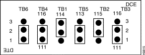
Example 1—Synchronous line with management of bit rate selection (CT111 for the modem), and local clock supplied on CT115 for DTE mode (CT109 absent). (See Figure 6-4.)
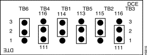
Example 2—Synchronous line with management of bit rate selection, and in DTE mode, receive clock identical to CT115. (See Figure 6-5.)
Example 3—Synchronous line with management of backup line selection (CT116 of the modem), and in DTE mode, local clocks supplied on CT115 (CT109 absent). (See Figure 6-6.)
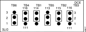
Example 4—Synchronous line with management of bit rate selection (CT116 of the modem), and in DTE mode, receive clock identical to CT115. (See Figure 6-7.)
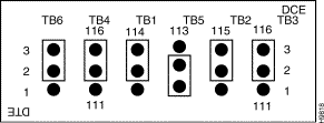
Example 5—Asynchronous line: No signals on pins 15 and 17. The position of TB6 is not significant. (See Figure 6-8.)
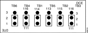
Jumper TB1 is factory set in position 2. It is used to enable/disable a Watchdog Timer. The default position is disabled.
Each jumper has two possible positions resulting in four possible combinations. These combinations are discussed below.
TB2 Position 2
TB3 Position 2
Enables reception of transmit and receive clock signals (CT114 and CT115) in DTE mode. In DCE mode clock signals are always provided by the FastPADmp.
TB2 Position 2
TB3 Position 1
This mode creates a switch for the receive clock in DTE mode. When Carrier Detect (CT109) is present on interface, the receive clock is taken from the DCE. When Carrier Detect is not present, the FastPADmp uses an internally generated receive clock. In DCE mode clock signals are always provided by the FastPADmp.
TB2 Position 1
TB3 Position 2
Enables reception of the external X.24 clock signals (CT114 A/B) in DTE mode. In DCE mode clock signals are always provided by the FastPADmp.
TB2 Position 1
TB3 Position 1
This mode creates a switch for the clock (CT114 A/B) in DTE mode. When the Indication signal (CT109 A/B) is present on interface, the receive clock is taken from the DCE. When the Indication signal is not present, the FastPADmp uses an internally generated receive clock. In DCE mode clock signals are always provided by the FastPADmp.
Line "Watchdog" Signal—Jumper TB1 is factory-set in position 2 (No LWD). Position 2 changes the V.11 outputs into high impedance under the command of the watchdog circuit (corresponding software module must also be installed).
CT114 and CT115 Signals—Jumpers TB2 and TB3 are used for the signals CT114 and CT115. There are four possible configurations that apply to either DCE OR DTE mode:
Example 1—Sets for reception of CT114 and CT115 in DTE mode. (See Figure 6-9.)

Example 2—In DTE mode only, sets for reception of CT114 and CT115 and the local clock replacing CT115 when CT109 is absent. (See Figure 6-10.)

Example 3—X.24 DTE mode. (See Figure 6-11.)

Example 4—X.24 DTE mode with local (reception) clock generation in the absence of signal 1A/1B. (See Figure 6-12.)

The following apply to the V.35 interface card:
1. The V.35 interface can also be set for either DTE or DCE mode.
2. There are no jumpers.
3. Maximum of two per module for stand-alone models.
4. Maximum of six per module for rack models.
This jumper is used as a switch to enable or disable local receive clock generation in the presence or absence of a Carrier Detect signal. Generally, a DCE device, such as a modem or CSU/DSU, supplies a Receive Clock signal to a DTE device.
When a FastPADmp is in DTE mode, it may either accept the receive clock from the DCE in all conditions, or it may supply its own local receive clock. By placing the jumper TB1 in the position <1-2>, the user configures the FastPADmp to generate its own receive clock when Carrier Detect (CT109) is absent. When Carrier Detect is asserted by the DCE, the FastPADmp will accept the Receive Clock (CT115) from the DCE.
By placing the jumper TB1 in the position <2-3>, the FastPADmp will always accept the Receive Clock from the DCE. Table 6-7 lists the choices.
| <1-2> | <2-3> | |
Carrier Detect Present | Clock from DCE | Clock from DCE |
Carrier Detect Not Present | Internal Clock | Clock from DCE |
When the FastPADmp or PCS is in DCE mode, the jumper setting is not relevant because the DCE interface supplies a clock, in all cases, to the corresponding DTE.
The ISDN S0 interface set meets the Safety Extra Low Voltage standard. This allows it to be connected to FastPAD products via the provided 25-pin connectors.
The other side of the ISDN S0 interface also meets the Safety Extra Low Voltage standard. It must be connected to an ISDN interface of the same standard.
All FastPADs can use an ISDN kit. The ISDN kit is a BRI access for reference point S/T. It meets the ITU-T requirements for T level I430 and requires phantom power to work.
The ISDN kit consists of three elements:
The ISDN adapter box contains the physical S0 interface, a 25-pin connector, and an RJ-45 connector socket.
The 25-pin connector is connected to the FastPAD in the line the user has chosen to use with the interface card.
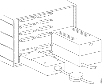
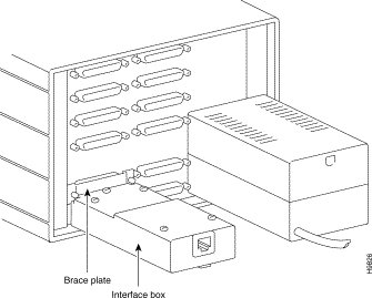
As shown in Figure 6-13, when the ISDN interface box is attached to the unit, it is secured with screws that attach to the port above the line to which the box is attached.
One screwdriver.
The use of the ISDN interface has implications for the use of adjacent lines.
The interface card IF-S0 is plugged into the port in use for the D-channel. The following port numbers (modulo 12) are assigned for the D-channel connection: 0, 3, 6, 9. If n is the number of the D-channel port, then n+1 and n+2 are reserved for the B-channels. If only one B-channel is used, then the n+2 port is available for other protocols. In all cases (except for mp6) with the external adapter box, the n+1 port is not available even if no B-channel is used (X.25 packet switching on D-channel), because of the ISDN's physical connection with the back panel. (See Figure 6-14.)
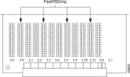
Table 6-8 summarizes the options. The ISDN interface box has a plate used as a brace which covers the adjacent port and is screwed into place to stabilize the physical connection of the ISDN box.
| Equipment Type | Port Number | SO/Module | SO/Unit |
|---|---|---|---|
mp6 | 0 | 1 | - |
mp | 0, 3, 6, 9 | 4 | - |
mp12 | 0, 3, 6, 9 (modulo 12) | 4 | 12 |
mpr | 0, 3/YB | 2 per YB | 8 |
The G.703 interface set meets the Safety Extra Low Voltage standard. (The interfaces are G.703-RJ-45 and G.703-BNC.) This allows the set to be connected to FastPAD products via the provided 25-pin connectors.
The other side of the G.703 interface also meets the Safety Extra Low Voltage standard. It must be connected to a G.703 interface of the same standard.
The G.703 interface connects the FastPAD to remote subscribers with a G.703 interface via a point-to-point connection. This is an unchannelized interface.
The G.703 interface kit consists of two components:
The G.703 adapter box contains the physical G.703 interface, a 25-pin connector, and an RJ-45 connector socket.
The 25-pin connector is connected to the FastPAD in the line associated with the interface card placement.
When the G.703 interface box is attached to the unit, it is secured with screws that attach to the port above the line to which the box is attached for bracing just as with the ISDN box. This line is covered by the braceplate and is unusable for any other purpose. (See Figure 6-15.)
If the G.703 interface is to be connected to an external device via the BNC connector, adapter box jumpers TB1, TB2, TB4, TB5, TB6, and TB7 should be left in position 1, the default position.
If the G.703 interface is to be connected to an external device via the RJ-45 connector, adapter box jumpers TB1, TB2, TB4, TB5, TB6, and TB7 should all be moved to position 2.
Jumper TB3 must match the jumpers TB3 and TB4 on the interface card: position 1 selects G.703 master interface, position 2 selects G.703 slave interface.
The G.703 has four jumpers as shown in Figure 6-16. Table 6-9 lists the jumpers and settings.
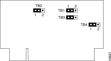
TB1 | 1 | "Blue Clock" management enabled by CT108 |
|
2 | "Blue Clock" management disabled by CT108 | Default value | |
TB2 | 1 | Local V.28 clock generated, enabled by CT107 |
|
2 | Utilization of Line Clock | Default value | |
TB3 and TB4 | 1 | G.703 master interface, generates 2 Mbits/sec line clock |
|
2 | G.703 slave interface | Default value |
The number of G.703 interfaces that can be connected to the FastPAD depends on the models to which they are connected:
The use of the IF-G.703 interface has implications for the use of the adjacent lines.
Since the connector above the G.703 interface box is used to secure the interface box to the FastPAD, the line associated with this connector is unusable.
The next available line (in the case of the G.703 interface being connected to line 0), line 2, has a maximum data rate of 256 Kbps.
![]()
![]()
![]()
![]()
![]()
![]()
![]()
![]()
Posted: Thu Jan 25 13:34:54 PST 2001
All contents are Copyright © 1992--2001 Cisco Systems, Inc. All rights reserved.
Important Notices and Privacy Statement.