|
|

Table Of Contents
Prerequisites for DOCSIS 1.1 Support
Restrictions for DOCSIS 1.1 Support
Information About DOCSIS 1.1 Support
Baseline Privacy Interface Plus
Additional DOCSIS 1.1 Features in Cisco IOS Release 12.2(15)CZ
Migrating from Earlier Versions of DOCSIS
How to Configure DOCSIS 1.1 Support
Creating a DOCSIS 1.1 Configuration File
Performing a Secure Software Download
Configuring for Provisioned Quality-of-Service
Verifying the DOCSIS 1.1 Configuration
Verifying the SNMPv3 Diffie-Hellman Configuration
Configuration Examples for DOCSIS 1.1 Support
debug cable-modem mac messages
show controllers cable-modem bpkm
show controllers cable-modem classifiers
show controllers cable-modem cmcert
show controllers cable-modem mac
show controllers cable-modem manuf-cert
show controllers cable-modem phs
show controllers cable-modem qos
show controllers cable-modem service-flows
snmp-server enable traps docsis-cm
DOCSIS 1.1 for Cisco uBR905 and Cisco uBR925 Cable Access Routers and Cisco CVA122 Cable Voice Adapters
This document describes the support for version 1.1 of the Data-over-Cable System Interface Specification (DOCSIS 1.1) in Cisco IOS Release 12.2(15)CZ for the Cisco uBR905 and Cisco uBR925 cable access routers and Cisco CVA122 cable voice adapter. This document focuses on the new software and the changes to the existing software architecture that provide DOCSIS 1.1 support. This document also describes Cable Modem Termination System (CMTS) to cable modem interoperability and provides instructions for migrating from DOCSIS 1.0 to DOCSIS 1.1.
Feature History for DOCSIS 1.1 Support
12.2(15)CZ
The DOCSIS 1.1 feature set was introduced for the Cisco uBR905 and Cisco uBR925 cable access routers and Cisco CVA122 cable voice adapter.
Finding Support Information for Platforms and Cisco IOS Software Images
Use Cisco Feature Navigator to find information about platform support and Cisco IOS software image support. Access Cisco Feature Navigator at http://www.cisco.com/go/fn. You must have an account on Cisco.com. If you do not have an account or have forgotten your username or password, click Cancel at the login dialog box and follow the instructions that appear.
Contents
This document includes the following sections:
•
Prerequisites for DOCSIS 1.1 Support
•
•
•
•
Prerequisites for DOCSIS 1.1 Support
Before you implement a DOCSIS 1.1 network, ensure that the following are true for your cable network:
•
Cisco uBR905/uBR925 Cable Access Routers and CVA122 Cable Voice Adapters at the following URL:
http://www.cisco.com/univercd/cc/td/doc/product/software/ios122/122newft/122limit/122cz/upgdcert.htm
Note
•
•
•
•
•
•
•
•
•
Restrictions for DOCSIS 1.1 Support
Cisco IOS Release
The Cisco uBR905 and Cisco uBR925 cable access routers and Cisco CVA122 cable voice adapters must be running Cisco IOS Release 12.2(15)CZ (or later release) to support DOCSIS 1.1. The CMTS must also support the DOCSIS 1.1 feature set.
Baseline Privacy Interface Plus
BPI+ encryption and authentication must be supported and enabled by both the cable modem and the CMTS. In addition, the CMTS and cable modem must contain a digital certificate that conforms to the DOCSIS 1.1 and BPI+ specifications.
Also, the DOCSIS specifications require that when the DOCSIS configuration file enables BPI or BPI+ encryption, the configuration file must also include a value for the Baseline Privacy Configuration Settings Option field (TLV 17). If this field is not included when BPI is enabled, the router rejects the BPI configuration. If MAC debugging is enabled (using the debug cable-modem mac command), the router also displays the displays the CMAC_LOG_BPKM_REQUIRED_TLV17_ABSENT debugging message on the console.
Note
http://www.cisco.com/univercd/cc/td/doc/product/software/ios122/122newft/122limit/122cz/upgdcert.htm
Tip
Maximum Burst Size
Previously, the maximum concatenated burst size parameter could be set to zero to specify an unlimited value. In a DOCSIS 1.1 environment, this parameter should be set to a nonzero value, with a maximum value of 1522 bytes for DOCSIS 1.0 cable modems.
If a cable modem attempts to register with a maximum concatenation burst size of zero, the DOCSIS 1.1 CMTS refuses to allow the cable modem to come online. This avoids the possibility that a DOCSIS 1.0 cable modem could interfere with voice traffic on the upstream by sending extremely large data packets. Since DOCSIS 1.0 does not support fragmentation, transmitting such data packets could result in unwanted jitter in the voice traffic.
In addition, DOCSIS 1.1 requires that the maximum transmit burst size be set to either 1522 bytes or the maximum concatenated burst size, whichever is larger. Do not set the maximum concatenation burst size to values larger than 1522 bytes for DOCSIS 1.0 cable modems.
Note
Provisioning
The format and content of the TFTP configuration file for a DOCSIS 1.1 cable modem are significantly different from the file for a DOCSIS 1.0 cable modem. A dual-mode configuration file editor is used to generate a DOCSIS 1.0 style configuration file for DOCSIS 1.0 cable modems and a DOCSIS 1.1 configuration file for DOCSIS 1.1 cable modems.
Registration
A DOCSIS 1.1 CMTS is designed to handle the existing registration TLVs from DOCSIS 1.0 cable modems as well as the new type TLVs from DOCSIS 1.1 cable modems. A DOCSIS 1.0 and DOCSIS 1.1 cable modem can successfully register with the same DOCSIS 1.1 CMTS.
A DOCSIS 1.1 cable modem can be configured to make an indirect reference to a service class that has been statically defined at the CMTS, instead of explicitly asking for particular service class parameters. When this registration request is received by a DOCSIS 1.1 CMTS, it encodes the actual parameters of the service class in the registration response and expects a DOCSIS 1.1-specific registration-acknowledge MAC message from the cable modem.
When a DOCSIS 1.1 cable modem registers with a DOCSIS 1.0 CMTS, it responds with DOCSIS 1.0 style registration messages and does not use the DOCSIS 1.1 feature set.
Performance
DOCSIS 1.0 cable modems lack the ability to explicitly request and provide scheduling parameters for advanced DOCSIS 1.1 scheduling mechanisms, such as unsolicited grants and real-time polling. DOCSIS 1.1 cable modems on the same upstream channel can benefit from the advanced scheduling mechanisms and a DOCSIS 1.1 CMTS can still adequately support voice traffic from DOCSIS 1.1 cable modems with DOCSIS 1.0 cable modems on the same upstream channel.
Information About DOCSIS 1.1 Support
DOCSIS 1.1 is the first major revision of the initial DOCSIS 1.0 standard for cable networks. Although the initial standard provided quality data traffic over the coaxial cable network, the demands of real-time traffic such as voice and video required many changes to the DOCSIS specification. DOCSIS 1.1 also includes support for the Baseline Privacy Interface Plus (BPI+) features, which improves and enhances the DOCSIS 1.0 BPI security and authorization mechanisms.
Note
The following sections describe the DOCSIS 1.1 features in more detail:
•
•
•
•
•
DOCSIS 1.1 Overview
The DOCSIS 1.1 specification provides the following functional enhancements over DOCSIS 1.0 coaxial cable networks:
•
–
–
–
–
•
–
–
–
–
–
•
–
–
Note
•
•
•
•
•
•
•
•
–
–
–
–
•
Baseline Privacy Interface Plus
DOCSIS 1.0 included a Baseline Privacy Interface (BPI) to protect user data privacy across the shared-medium cable network and to prevent unauthorized access to DOCSIS-based data transport services across the cable network. BPI encrypts traffic across the RF interface between the cable modem and CMTS, and also includes authentication, authorization, and accounting (AAA) features.
BPI supports access control lists (ACLs), tunnels, filtering, protection against spoofing, and commands to configure source IP filtering on RF subnets to prevent subscribers from using source IP addresses that are not valid. These lists can be implemented either through CLI commands or by setting SNMP attributes through the DOCSIS configuration file.
DOCSIS 1.1 enhances these security features with Baseline Privacy Interface Plus (BPI+), which includes the following enhancements:
•
•
•
•
•
Note
X.509 Digital Certificates
BPI+ uses digital certificates and a public key infrastructure (PKI) that are based on the International Telecommunications Union (ITU) X.509 Version 3.0 standard. The key components of the X.509 standard are the following:
•
–
–
–
–
A DOCSIS 1.1 cable modem contains two digital certificates programmed into it at the factory: a cable modem certificate that uniquely identifies it, and a manufacturing certificate that identifies the cable modem's manufacturer (in this case, Cisco Systems).
•
Note
•
•
•
•
During BPI+ initialization, the cable modem sends both of its signed digital certificates, the cable modem certificate (CMC) and the manufacturer's certificate (MC), to the CMTS. The CMTS verifies the cable modem certificate against the manufacturer's certificate, and then verifies the manufacturer's certificate against the DOCSIS Root CA certificate. This chain of verifications ensures that the CMTS can securely identify and authenticate each cable modem.
In addition, the CMTS can check the certificates against a Hot List of invalid certificates. The Hot List, which can be maintained by trusted authorities, such as a service provider or CA, can list certificates for individual cable modems that might have been stolen, hacked, or otherwise compromised. The list can also contain manufacturer's certificates for models of cable modems that the service provider does not support.
If all certificate verifications are successful, the CMTS begins the public key exchange process, which allows data encryption and decryption to begin.
Public Key Exchange
The secure use of X.509 digital certificates depends on both the cable modem and the CMTS possessing the proper encryption and decryption keys. For security and flexibility, DOCSIS 1.1 uses a dual-key public key exchange: the first set of keys, key encryption key (KEK), are used to encrypt and transmit the second set of keys, traffic encryption key (TEK), which are then used to encrypt and decrypt data.
Both sets of keys have a limited lifetime and must be renewed periodically. When a key reaches approximately half its lifespan, the cable modem begins the process to request a new set of keys. While the new set of keys is being exchanged, the cable modem can continue to use the old set to encrypt and decrypt data. The KEK keys have a longer lifetime than the TEK keys to ensure that the cable modem and CMTS will always be able to obtain new TEK keys, allowing data transmissions to continue without interruptions.
Secure Software Download
DOCSIS 1.1 supports secure software download to allow a service provider to remotely upgrade a cable modem's software without risk of interception or alteration. Secure software download also prevents users from upgrading the cable modem to unauthorized software images.
The manufacturer digitally signs the software image using a Pkcs#7 digital signature that is encrypted using the Rivest-Shamir-Adleman (RSA) algorithm and secure hash algorithm-1 (SHA-1). This digital signature is chained to the DOCSIS root code signing certificate so that it can be easily verified.
The cable operator can optionally also digitally sign the software image in a similar manner, using another digital signature that is chained to the DOCSIS root code signing certificate. This allows cable operators greater control over which software images are used on the cable network.
The cable operator initiates the software download by filling in the software filename and TFTP server fields (TLVs 9 and 21) in the DOCSIS configuration file that it sends to the cable modem during registration. You can also initiate a software download by using SNMP commands. In either case, the cable modem then requests the specified file and downloads it from the specified TFTP server.
The cable modem verifies the manufacturer's digital signature and, if present, the cable operator's digital signature, using the code verification certificates (CVCs) provided in the DOCSIS configuration file. If the signatures are valid, the cable modem loads and runs the software.
When a cable modem is running DOCSIS 1.1 software, it must use the secure software download feature to download a software image through the DOCSIS configuration file or through SNMP commands. Even if you disable BPI+, a DOCSIS 1.1 cable modem still accepts only digitally signed software images that can be verified through the secure software download process.
Note
The secure software download feature requires the following prerequisites:
•
If the cable modem is currently running a DOCSIS 1.0 software image, you cannot use the secure software download to upgrade to a DOCSIS 1.1 image. Instead, you must use the DOCSIS 1.0 software upgrade process to load an unsigned DOCSIS 1.1 software image. Then you will be able to use the secure software download process to load a digitally signed DOCSIS 1.1 software image.
•
Note
•
–
–
If you load the M-CVC into the cable modem, you can download only those software images that Cisco Systems has digitally signed. If you load the C-CVC into the cable modem, you can download only those software images that Cisco Systems and the cable operator have digitally signed.
Note
After the cable modem loads and runs the DOCSIS 1.1 image, the cable modem must use the secure software download process for all future upgrades. In particular, this means that the cable modem cannot be downgraded to a DOCSIS 1.0 software image unless the manufacturer provides a digitally signed DOCSIS 1.0 image. After downgrading to a DOCSIS 1.0 image, you cannot use the secure software download process again until you have upgraded the cable modem to a new DOCSIS 1.1 image.
Tip
DOCSIS 1.1 Quality-of-Service
DOCSIS 1.1 implemented a number of changes to allow great flexibility in the ability of a cable modem and service provider to transmit almost any combination of data traffic and real-time traffic, such as voice and video. These changes required a fundamental shift in how a cable modem requests service and how traffic can be transmitted across the cable network.
Overview
The DOCSIS 1.1 QoS framework is based on the following objects:
•
•
•
•
In the upstream direction, the output queues at the cable modem get remotely served by the CMTS MAC scheduler, based on DOCSIS 1.1 slot scheduling constraints such as grant-interval and grant-jitter. In the downstream direction, the CMTS packet scheduler serves the flow queues depending on the flow attributes like traffic priority, guaranteed rate, and delay bound.
DOCSIS 1.1 adds several new MAC scheduling disciplines to provide guaranteed QoS for real-time service flows on the multiple access upstream channel. Multiple grants per interval helps in supporting multiple subflows (such as voice calls) on the same SID. Multiple subflows per SID reduces the minimum SID requirement in cable modem hardware.
The CMTS is responsible for supporting QoS for all cable modems in its control. The traffic in the downstream is assumed to be a combination of voice, committed information rate (CIR) data, and excess burst best-effort data. To provide QoS support, the following functions must be performed:
•
•
•
•
The admission control block helps the overall downstream QoS block to track the current bandwidth reservation state on a per-downstream basis. Decisions can be made whether to admit or reject a request for a new service flow on that DS channel, based on this reservation state and the QoS guarantees requested by the new service-flow.
IP packet classifiers help in filtering out unique service flows on an interface for differential QoS treatment. Rather than doing per-cable modem downstream rate shaping, DOCSIS 1.1 software provides rate shaping at a much more granular level of individual service flows of the cable modem.
Note
Service Flows and Packet Classifiers
Every cable modem establishes a primary service flow in both the upstream and downstream directions. The primary flows maintain connectivity between the cable modem and the CMTS at all times.
In addition, a DOCSIS 1.1 cable modem can establish multiple secondary service flows. The secondary service flows either can be permanently created (they persist until the cable modem is reset or powered off) or can be created dynamically to meet the needs of the on-demand traffic being transmitted.
A service flow gets created at the time of cable modem registration (a static service flow) or as a result of a dynamic MAC message handshake between the cable modem and the CMTS (a dynamic service flow). At any given time, a service flow might be in one of three states (provisioned, admitted, or active). Only active flows are allowed to pass traffic on the DOCSIS link.
Each service flow has a set of QoS attributes associated with it. These QoS attributes define a particular class of service and determine characteristics such as the maximum bandwidth for the service flow and the priority of its traffic. The class of service attributes can be inherited from a preconfigured CMTS local service class (class-based flows), or they can be individually specified at the time of the creation of the service flow.
Every service flow also has a unique (unique per DOCSIS MAC domain) identifier called the service flow identifier (SFID). The upstream flows in the admitted and active state have an extra Layer 2 SID associated with them. The SID is the identifier used by the MAC scheduler when specifying time-slot scheduling for different service flows.
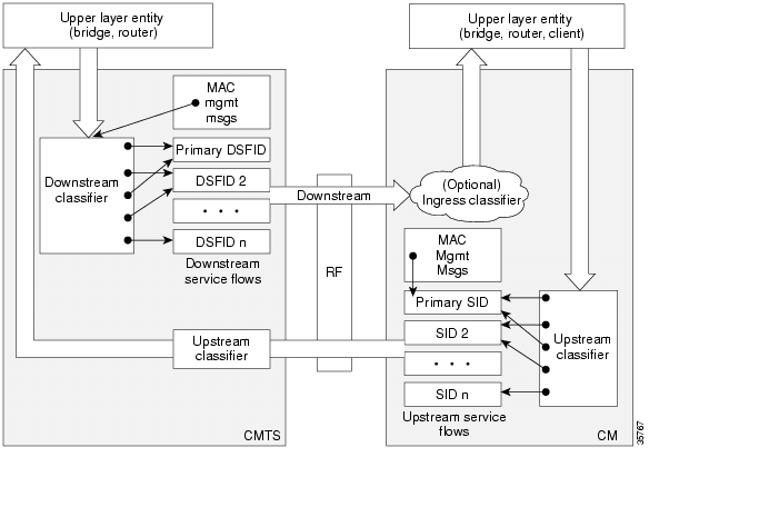
Each service flow has multiple packet classifiers associated with it, which determine the type of application traffic allowed to be sent on that service flow. Each service flow can also have a payload header suppression (PHS) rule associated with it to determine which portion of the packet header will be suppressed when packets are transmitted on the flow.
Figure 1 illustrates the mapping of packet classifiers.
Figure 1 Classification Within the MAC Layer
Dynamic Channel Change
DOCSIS 1.1 supports Dynamic Channel Change (DCC) requests, which allow the CMTS to change the upstream or downstream frequency that the cable modem is using. This allows the CMTS to move cable modems to another channel when the current one is either becoming congested or is encountering growing noise problems that could eventually force the cable modems offline.
The Cisco uBR905 and Cisco uBR925 cable access routers and the Cisco CVA122 Cable Voice Adapter automatically support DCC requests when running Cisco IOS Release 12.2(15)CZ.
Dynamic Quality-of-Service
DOCSIS 1.1 adds support Dynamic Services MAC-layer messages that provide for Dynamic QoS (DQoS) between the cable modem and the CMTS. These messages are DOCSIS link-layer equivalents of the higher-layer messages that create, tear down, and modify a service flow. These messages are collectively known as DSX messages to represent the three types of dynamic service messages:
•
•
–
–
–
•
The DSX state machine module on the cable modem manages the several concurrent dynamic service transactions between cable modems and the CMTS. The DSX state machine supports all three DOCSIS1.1 DSX MAC messages (DSA, DSC, DSD).
Provisioned QoS
Provisioned QoS (PQoS) allows the cable modem to create the service flows it needs for voice calls and other real-time traffic at the time it registers with the CMTS, without actually using the bandwidth for those flows. The service flow is kept in the admitted state and is activated only when the cable modem signals a voice call using the DOCSIS 1.1 Dynamic Service Request (DSC-REQ) message. Bandwidth is used only when the voice call is actually in progress.
To use PQoS services, you must configure the cable modem with secondary service flows for VoIP calls. (If you do not define any secondary service flows, DQoS is used instead of PQoS). You can use any voice signaling that is supported by the cable modem for VoIP traffic.
Table 1 compares how the router sets up and tears down VoIP calls when using DQoS and PQoS:
Service Flow Manager
The Service Flow Manager is a new module that manages different activities related to service flows on a cable interface. Typical events include the creation of new DOCSIS service flows, modification of the attributes of existing service flows, and the deletion of service flows.
Quality-of-Service Comparison
Quality-of-service (QoS) is a measure of performance for a transmission system that reflects its transmission quality and service availability. This section describes the differences in QoS between DOCSIS 1.1 and DOCSIS 1.0 and 1.0+.
DOCSIS 1.0
DOCSIS 1.0 uses a static QoS model that is based on a class of service (CoS) that is preprovisioned in the TFTP configuration file for the cable modem. The CoS is a bidirectional QoS profile that has limited control, such as peak rate limits in either direction and relative priority on the upstream.
DOCSIS 1.0 defines the concept of a service identifier (SID), which specifies the devices allowed to transmit and which provides device identification and CoS. In DOCSIS 1.0, each cable modem is assigned only one SID, creating a one-to-one correspondence between a cable modem and the SID. All traffic originating from, or destined for, a cable modem is mapped to that cable modem's SID.
Typically, a DOCSIS 1.0 cable modem has one CoS and treats all traffic the same, which means that data traffic on a cable modem can interfere with the quality of a voice call in progress. The CMTS, however, can prioritize downstream traffic based on IP precedent type-of-service (ToS) bits. For example, voice calls using higher IP precedence bits receive a higher queueing priority (but without a guaranteed bandwidth or rate of service). A DOCSIS 1.0 cable modem could increase voice call quality by permanently reserving bandwidth for voice calls, but then that bandwidth would be wasted whenever a voice call is not in progress.
DOCSIS 1.0+ Extensions
In response to the limitations of DOCSIS 1.0 in handling real-time traffic, such as voice calls, Cisco created the DOCSIS 1.0+ extensions to provide the more important QoS enhancements that were expected in DOCSIS 1.1. In particular, the DOCSIS 1.0+ enhancements provide basic Voice-over-IP (VoIP) service over the DOCSIS link.
Cisco DOCSIS 1.0+ extensions include the following DOCSIS 1.1 features:
•
•
•
•
•
Caution
SNMPv3 Support
DOCSIS 1.1 also requires support of v3 of the Simple Network Management Protocol (SNMPv3). SNMPv3 offers a number of significant improvements over SNMPv1 and SNMPv2:
•
•
•
SNMPv3 Diffie-Hellman Kickstart
To ensure SNMPv3 security, the Multi-Service Operator (MSO) must perform an initialization procedure the first time the cable modem comes online. This procedure, which the DOCSIS 1.1 specification refers to as the SNMPv3 Diffie-Hellman Kickstart, sends a public key to the cable modem as part of the DOCSIS configuration file. The cable modem creates a secret number and encrypts it using the public key it received in the configuration file.
The cable modem then publishes the encrypted number to the CMTS, which uses its private key to decrypt it so as to produce the cable modem's secret number. This secret number becomes a shared secret value that the CMTS and CM can use to exchange SNMPv3 encryption keys.
For information on the SNMPv3 Diffie-Hellman Kickstart configuration, see the "Configuring the SNMPv3 Diffie-Hellman Kickstart Public Key" section.
MIB Enhancements
DOCSIS 1.1 also expands the MIB support for SNMP management, including the following changes and additions to the DOCSIS 1.0 MIB structure:
•
•
•
•
•
•
Additional DOCSIS 1.1 Features in Cisco IOS Release 12.2(15)CZ
The following sections describe the DOCSIS 1.1 software features that appear in Cisco IOS Release 12.2(15)CZ.
Concatenation
Concatenation allows the cable modem to make a single time-slice request for multiple packets and send all packets in a single large burst on the upstream. Concatenation was introduced in the upstream receive driver in DOCSIS1.0+ releases.
Fragmentation
Grant fragmentation allows the upstream MAC scheduler to slice large data requests to fit into the scheduling gaps between UGS (voice slots). This reduces the jitter experienced by the UGS slots when large data grants preempt the UGS slots. The grant fragmentation gets triggered in the MAC scheduler, and fragment reassembly happens in the upstream receive driver.
Note
IP Multicast Support
By default, a DOCSIS CMTS transmits IP multicast traffic without encryption. All DOCSIS cable modems receiving that multicast traffic must forward it to its attached CPE devices, without regard to whether any of the devices have requested the traffic. This can waste network bandwidth and require network devices to waste processor power in forwarding and processing undesired multicast traffic.
A DOCSIS 1.1 CMTS can instead use the Internet Group Management Protocol (IGMP) to maintain the multicast group memberships of its DOCSIS 1.1 cable modems. BPI+ encryption is used to encrypt the multicast packets so that only the cable modems with the appropriate public keys can decrypt the packets and forward them to their attached customer premises equipment (CPE) devices.
If a cable modem has not been granted the decryption keys for a particular multicast service flow, it does not forward the traffic to its CPE devices. This ensures that only authorized subscribers can receive the multicast traffic, and prevents cable modems from loading down their local networks by forwarding unnecessary multicast traffic.
DOCSIS 1.1 uses the concept of Security Associations (SA), which are dynamically created and maintained to provide the service flows required to transmit IP multicast traffic on the downstream. A cable modem sends an SA Map Request message to request the SA for the downstream service flow that is carrying the desired multicast traffic.
If the cable modem is not authorized to receive the multicast traffic, or if the traffic is not available on BPI+ encrypted SA, the CMTS sends an SA Map Reject message. The cable modem then does not repeat any further SA Map Requests for this particular multicast traffic. However, if the traffic is available on an unencrypted service flow, it begins forwarding that traffic to its CPE devices.
If the cable modem is authorized to receive the multicast traffic, and if the traffic is available, the CMTS replies with an SA Map Reply message to provide the information that allows the cable modem to receive the multicast traffic. The SA Map Reply message contains the SA identifier (SAID) for the traffic and the cryptographic suite that is necessary to decrypt the multicast traffic.
If the cable modem supports the cryptographic suite being used, it sends a Key Request to the CMTS, requesting the public keys it needs to decrypt the multicast service flow. If the CMTS replies with a Key Reply that contains the requested public keys, the cable modem begins decrypting the multicast traffic and forwarding it to its attached CPE devices.
The multicast traffic can be mapped to the cable modem's primary SA, a static SA, or a dynamically created SA. One service flow can support multiple multicast traffic flows, each with its own SAID. Multicast traffic mapped to a primary SA can be received only by the cable modem that is assigned the associated primary service flow. Multicast traffic mapped to static and dynamic SAs can be received by all cable modems that are assigned the associated secondary service flows.
Payload Header Suppression and Restoration
The PHS feature is used to suppress repetitive or redundant portions in packet headers before transmission on the DOCSIS link. This is a new feature in the DOCSIS1.1 MAC driver. The upstream receive driver is now capable of restoring headers suppressed by cable modems, and the downstream driver is capable of suppressing specific fields in packet headers before forwarding the frames to the cable modem.
Migrating from Earlier Versions of DOCSIS
DOCSIS 1.1 cable modems have additional features and better performance than earlier DOCSIS 1.0 and 1.0+ models, but all three models can coexist in the same network. DOCSIS 1.0 and 1.0+ cable modems will not hamper the performance of a DOCSIS 1.1 cable modem, nor will they interfere with operation of DOCSIS 1.1 features. There is full forward and backward compatibility in the standards.
Benefits
DOCSIS 1.1 includes a rich set of features that provide advanced and flexible QoS capabilities for various types of traffic (voice, data, and video) over the cable network. It also provides enhanced security and authentication features.
Baseline Privacy Interface Plus Enhancement
The Plus (+) version of the Baseline Privacy Interface (BPI+) in DOCSIS 1.1 provides a set of extended services within the MAC sublayer that increase performance and system security. Digital certificates provide secure authentication for each cable modem, to prevent identity theft on the basis of MAC and IP addresses. Advanced encryption provides a secure channel between the cable modem and the CMTS, and secure software download allows a service provider to upgrade the software on cable modems, without the threat of interception, interference, or alteration of the software code.
Dynamic Service Flows
The dynamic creation, modification, and deletion of service flows allows for on-demand reservation on Layer 2 bandwidth resources. The CMTS can now provide special dynamic QoS (DQos) to the cable modem dynamically for the duration of a voice call or video session, as opposed to the static provisioning and reservation of resources at the time of cable modem registration. This provides a more efficient use of the available bandwidth.
Concatenation
The cable modem concatenates multiple upstream packets into one larger MAC data frame, allowing the cable modem to make only one time-slot request for the entire concatenated MAC frame, as opposed to requesting a time slot for each individual packet. This reduces the delay in transferring the packet burst upstream.
Enhanced QoS
Extensive scheduling parameters allow the CMTS and the cable modem to communicate QoS requirements and achieve more sophisticated QoS on a per service-flow level.
Different new time-slot scheduling disciplines help in providing guaranteed delay and jitter bound on shared upstream. Activity detection helps to conserve link bandwidth by not issuing time slots for an inactive service flow. The conserved bandwidth can then be reused for other best-effort data slots.
Packet classification helps the CMTS and the cable modem to isolate different types of traffic into different DOCSIS service flows. Each flow could be receiving a different QoS service from the CMTS.
Provisioned QoS
Provisioned QoS (PQoS) allows the cable modem to create service flows for voice calls and other real-time traffic at the time it registers with the CMTS, without actually using the bandwidth for those flows. When such a service flow is specified in the DOCSIS configuration file, the cable modem creates a flow that uses the DOCSIS 1.1 unsolicited grant service (UGS). The service flow, however, is not activated until the cable modem signals the voice call using the DOCSIS 1.1 Dynamic Service Change Request (DSC-REQ) message. Bandwidth is used only when the voice call is actually in progress.
Fragmentation
The MAC scheduler fragments data slots to fill the gaps in between UGS slots. Fragmentation reduces the jitter experienced by voice packets when large data packets are transmitted on the shared upstream channel and preempt the UGS slots used for voice. Fragmentation splits the large data packets so that they fit into the smaller time slots available around the UGS slots.
Multiple Subflows per SID
This feature allows the cable modem to have multiple calls on a single hardware queue. This approach scales much better than requiring a separate SID hardware queue on the cable modem for each voice call.
Payload Header Suppression
Payload header suppression (PHS) allows the CMTS and the cable modem to suppress repetitive or redundant portions in packet headers before transmitting on the DOCSIS link. This helps to conserve link bandwidth, especially with types of traffic, such as voice, where the header size tends to be as large as the size of the actual packet.
Service Classes
The QoS attributes of a service flow can be specified in two ways: either explicitly by defining all attributes, or implicitly by specifying a service class name. A service class name is a string that the CMTS associates with a QoS parameter set.
The service class serves the following purposes:
•
•
•
Note
Any service flow can have its QoS parameter set specified in any of three ways:
Ζ By explicitly including all traffic parameters.
Ζ By indirectly referring to a set of traffic parameters by specifying a service class name.
Ζ By specifying a service class name along with modifying parameters.
The service class name is expanded to its defined set of parameters at the time the CMTS successfully admits the service flow.
Secure Software Download
Secure software download ensures that the cable modem downloads only the proper software image from a properly authenticated server. The software transfer is encrypted to prevent users and hackers from intercepting the download and substituting their own software image in its place.
How to Configure DOCSIS 1.1 Support
The Cisco uBR905 and Cisco uBR925 cable access routers and Cisco CVA122 cable voice adapters automatically support all DOCSIS 1.1 features when running Cisco IOS Release 12.2(15)CZ. Many DOCSIS 1.1 features, however, must be specifically enabled through the DOCSIS configuration file that is downloaded to the router at initialization time. Special configuration is also needed to use provisioned quality-of-service (PQoS) for VoIP calls.
See the following sections for the configuration tasks for each feature. Each tasks in the list is identified as either required or optional.
•
•
•
•
•
Creating a DOCSIS 1.1 Configuration File
No special configuration is needed to enable basic DOCSIS 1.1 operation, but the DOCSIS configuration file can be used to control which DOCSIS 1.1 features are enabled and used during a session.
In addition to enabling the different DOCSIS 1.1 features, special fields in the DOCSIS configuration files are needed to enable SNMPv3 operation and to configure the router for the secure software download procedure. The following sections describe these procedures:
•
•
•
These procedures assume that you are using the Cisco DOCSIS Configurator Tool, version 3.6 or later, to generate the DOCSIS 1.1 configuration files for the cable modems. This tool is available on Cisco.com at http://www.cisco.com/cgi-bin/tablebuild.pl/cpe-conf.
DOCSIS 1.1 Feature Configuration
A DOCSIS 1.1-capable cable modem informs the CMTS that it is capable of DOCSIS 1.1 operation by sending a DHCP request that includes option 60, Vendor Class Identifier, with a value of "docsis1.1:xxxxxxx", where xxxxxxx is an ASCII string with the hexadecimal encoding of the encoding of the modem's capabilities. This field informs the CMTS of the following information:
•
•
•
•
•
•
•
•
•
•
The option 60 message does not enable DOCSIS 1.1 operation but only informs the CMTS of the cable modem's capabilities. To enable the different DOCSIS 1.1 features, you must specifically enable the following options in the DOCSIS configuration file:
•
•
•
•
•
•
Note
Configuring the SNMPv3 Diffie-Hellman Kickstart Public Key
Before a DOCSIS 1.1 cable modem can initiate BPI+ encryption, it must be configured with a shared public key that allows it to securely transfer the BPI+ encryption keys with the CMTS. Use the following procedure to configure the Cisco uBR905, Cisco uBR925, or Cisco CVA122 with the required public key.
The DOCSIS 1.1 specification refers to this procedure as SNMPv3 Diffie-Hellman Kickstart. This procedure needs to be done only once, unless the public keys are changed on the CMTS, or the Cisco uBR905, Cisco uBR925, or Cisco CVA122 is moved to a different CMTS that uses a different public key.
Step 1
Step 2
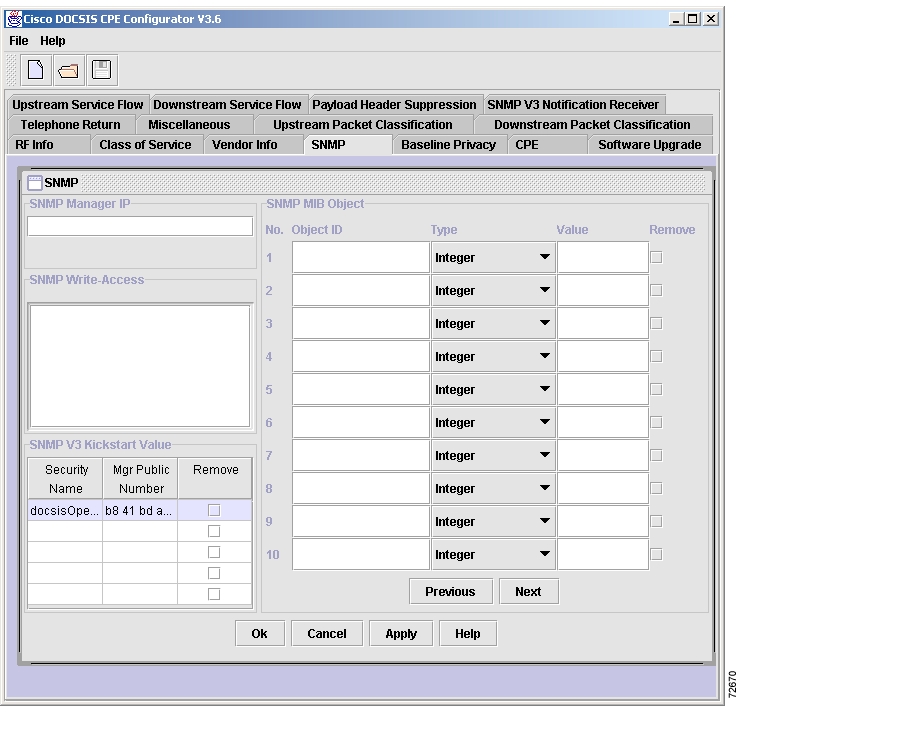
For example, if you are creating an ASCII file and using the Cisco DOCSIS Configurator tool to convert it into the binary DOCSIS configuration file, you would specify lines such as the following:
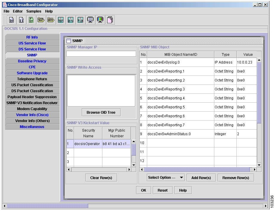
34 (SNMPv3 Kickstart Values)S01 (Kickstart Security Name) = docsisOperatorS02 (Kickstart Mgr Public Number) = b1 01 c2 0F F4 3C ... (exactly 128 hex bytes)To enter this data directly into the Configurator tool, click on the SNMP tab and enter this data into the first available row in the "SNMP V3 Kickstart Value" table. Figure 2 shows an example of this using version 3.7 of the Cisco DOCSIS Configurator tool. Figure 3 shows an example of this using version 4.0 of the Cisco Broadband Configurator tool.
Figure 2 Entering the Kickstart Values into Cisco DOCSIS Configurator Version 3.7
Figure 3 Entering the Kickstart Values into Cisco Broadband Configurator Version 4.0
Tip
Step 3
Configuring for Secure Software Download
Before a DOCSIS 1.1 cable modem can perform a secure software download, it must be configured with the code verification certificates (CVCs) that allow it to securely transfer the software file from the CMTS. The manufacturer's CVC (M-CVC) verifies that the software image has been properly signed by the manufacturer (in this case, Cisco Systems). The optional cosigner's CVC (C-CVC) verifies that the software image has been signed by the Multi-Service Operator (MSO) that is providing the cable network.
Use the following procedure to configure the Cisco uBR905, Cisco uBR925, or Cisco CVA122 with the required certificates.
Step 1
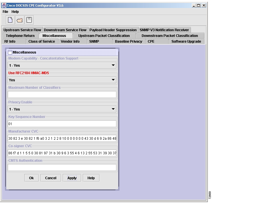
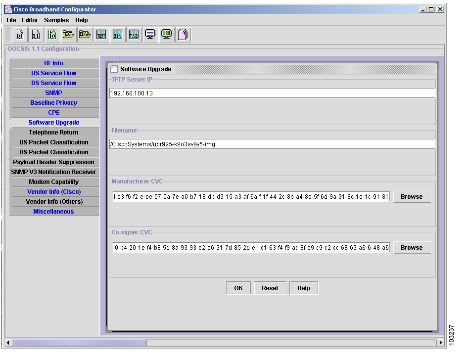
Figure 4 shows an example of this using version 3.7 of the Cisco DOCSIS Configurator tool. Figure 5 shows an example of this using version 4.0 of the Cisco Broadband Configurator tool.
Figure 4 Entering the M-CVC into Cisco DOCSIS Configurator Release 3.7
Figure 5 Entering the M-CVC into Cisco Broadband Configurator Release 4.0
Tip
You can also create an ASCII file and use the DOCSIS Configurator tool to convert it into the binary DOCSIS configuration file. However, if the M-CVC contains more than 254 bytes, you must break it apart into successive fields, with each field except the last containing exactly 254 bytes.
The following shows a typical example of an M-CVC that is greater than 254 bytes:
32 (Manufacturer CVC) = 30 A2 4E 23 ... F1 C5 (exactly 254 bytes)32 (Manufacturer CVC) = 21 36 A4 9F ... 3E 13 (exactly 254 bytes)32 (Manufacturer CVC) = 0F 12 13 (254 bytes or less)If you are using Release 3.7 or later of the DOCSIS Configurator tool, you can also specify TLV 320, which allows you to specify the location of the actual M-CVC binary file on the local disk. The Configurator then reads the file and saves the CVC as part of the DOCSIS configuration file. This avoids having to convert the CVC into a hexadecimal format, as shown above.
For example, if you are running the DOCSIS Configurator on a Windows workstation, and you have saved the M-CVC in the file D:\CiscoM.cvc, use the following line into the ASCII file:
320 (Manufacturer CVC) = D:\CiscoM.cvcStep 2
If you are creating an ASCII configuration file and converting it into the binary DOCSIS configuration file, and if the C-CVC contains more than 254 bytes, you must break it apart into successive TLV 33 fields, and each field except the last must contain exactly 254 bytes. The following shows a typical example of an C-CVC that is greater than 254 bytes:
33 (Co-signer CVC) = 03 2A E4 35 ... E7 D2 (exactly 254 bytes)33 (Co-signer CVC) = 12 A4 36 4B ... 11 1F (exactly 254 bytes)33 (Co-signer CVC) = AB D0 F4 (254 bytes or less)If you are using Release 3.7 or later of the DOCSIS Configurator tool, you can also specify TLV 330, which allows you to specify the location of the actual C-CVC binary file on the local disk. The Configurator then reads the file and saves the CVC as part of the DOCSIS configuration file. This avoids having to convert the CVC into a hexadecimal format, as shown above.
For example, if you are running the DOCSIS Configurator on a Windows workstation, and you have saved the C-CVC in the file D:\MSO.cvc, use the following line into the ASCII file:
330 (Co-signer CVC) = D:\MSO.cvc
Note
Step 3
Performing a Secure Software Download
Use the following procedures to download a digitally signed software image to the router using the secure software download procedure.
•
•
These procedures assume that the required CVCs have been downloaded to the router (see the "Configuring for Secure Software Download" section) and that the router is already running a DOCSIS 1.1 software image.
Note
Caution
Tip
Downloading the Image During Initialization Through the DOCSIS Configuration File
After you have upgraded the router to Cisco IOS Release 12.2(15)CZ, or another DOCSIS 1.1 software image, the router must use the DOCSIS 1.1 secure software download feature to upgrade its software image. During initialization, the cable modem compares its current software image with the one specified in the DOCSIS configuration file and, if they do not match, the cable modem downloads the new software image from the specified TFTP server. The router verifies the digital signature of the downloaded file to ensure that the software image has not been corrupted or altered during transmission.
Use the following procedure to copy the Cisco IOS software image and new DOCSIS 1.1 certificates to the TFTP server used by the cable modems.
Note
Step 1
For a DOCSIS secure software download, you must use a digitally signed software image, which includes "cvc" as part of the software image filename.
Note
Step 2
•
•
•
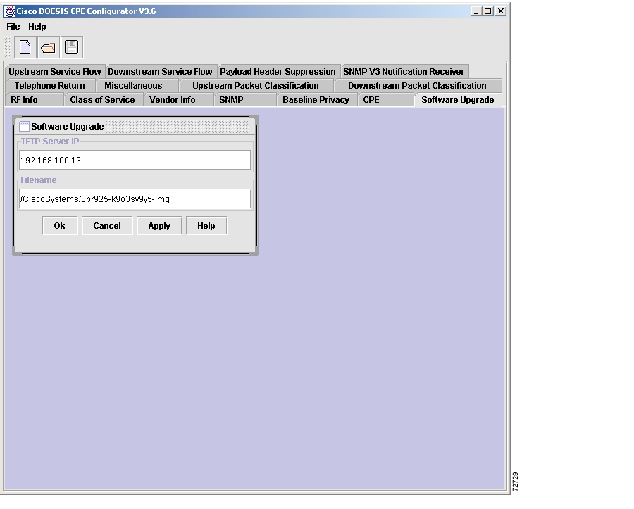
You can create this file using any DOCSIS 1.1 configuration file editor, such as the Cisco DOCSIS Configurator Tool (release 3.7). For example, Figure 6 shows an example that specifies the image ubr925cvc-k9o3sv9y5-mz in the directory /CiscoSystems on the TFTP server at IP address 192.168.100.13. (See Figure 5 for an example of Cisco Broadband Configurator version 4.0.)
Figure 6 Software Upgrade Parameters
If you are creating an ASCII configuration file and using the DOCSIS Configurator tool to convert it into the binary DOCSIS configuration file, you would enter these same values as follows:
09 (Software Upgrade Filename) = /CiscoSystems/ubr925cvc-k9o3sv9y5-mz21 (TFTP Server IP) = 192.168.100.13Step 3
Step 4
Step 5
Step 6
When the router or Cisco CVA122 Cable Voice Adapter is restarted, it downloads the DOCSIS 1.1 configuration file, which forces the router to download the Cisco IOS Release 12.2(15)CZ software image using the DOCSIS secure software download. The router then reloads and boots the Cisco IOS Release 12.2(15)CZ image.
Downloading the Image After Initialization Through SNMP
You can download a new software image to a DOCSIS 1.1 cable modem by setting the following SNMP attributes in the DOCS-CABLE-DEVICE-MIB:
•
•
•
You can monitor the status of the download by polling the docsDevSwOperStatus attribute, which returns 1 (inProgress) while the download is progressing and 3 (completeFromMgt) when the download is complete. You can also enable Secure Software Download traps using the snmp-server enable traps docsis-cm command, so that the SNMP manager is notified when the download succeeds.
Note
Configuring for Provisioned Quality-of-Service
To use provisioned quality-of-service (PQoS) for outgoing VoIP calls, configure the outgoing dial-peer with the req-qos command, and optionally with the ip qos dscp command. The following example shows an H.323v2 dynamic mapping configuration for an outgoing dial peer that uses the Registration, Admission, and Status (RAS) protocol to allow a remote gatekeeper to translate phone numbers (E.164 addresses) to the IP addresses of the specific dial peers.
Note
Cisco IOS Voice, Video, and Fax Configuration Guide, Release 12.2T.
SUMMARY STEPS
1.
2.
3.
4.
5.
6.
7.
8.
9.
10.
11.
12.
13.
DETAILED STEPS
Verifying the DOCSIS 1.1 Configuration
To display the DOCSIS 1.1 QoS statistics, including the type of service flow and packet classifiers being used for each queue, use the show controllers cable-modem qos command:
Router# show controllers cable-modem 0 qosQueue SID SID SFID TX TX RX RX CapabilitiesType Pkts Bytes Pkts Bytes cbr cc fr nbr0 1 Primary 3 40 5740 2780 209346 F T T F1 56 Dynamic 91 1782 160140 0 0 T T T T2 58 Dynamic 93 690 61946 0 0 T T T T3 0 NA 0 0 0 0 0 F F F FQueue SF Type0 BE1 BE2 UGS_AD3 NAPacket ClassifiersClass id SFID Pri valid Match SIDT1 91 0 D6 1782 80D2754C2 93 0 D6 691 80D275C0Packet Classifier DetailsClassifier id = 1 SFID = 91IP source: 10.188.1.88IP dest: 10.188.1.66UDP/TCP source range: 18416 to 18416UDP/TCP dest range: 16740 to 16740IP Protocol: 17PHS: InactiveClassifier id = 2 SFID = 93IP source: 10.188.1.88IP dest: 10.188.1.66UDP/TCP source range: 16796 to 16796UDP/TCP dest range: 19138 to 19138IP Protocol: 17PHS: InactiveDownstream Payload Header SuppressionRouter#Verifying the SNMPv3 Diffie-Hellman Configuration
Use the following procedure to verify that the SNMPv3 Diffie-Hellman Kickstart configuration has been accomplished and that SNMPv3 operations are enabled on the router.
Step 1
Router# show snmp userUser name: docsisUserEngine ID: 800000090300000164FFE2E0storage-type: nonvolatile activeUser name: dhKickstartEngine ID: 800000090300000164FFE2E0storage-type: permanent activeUser name: docsisManagerEngine ID: 800000090300000164FFE2E0storage-type: nonvolatile activeUser name: docsisMonitorEngine ID: 800000090300000164FFE2E0storage-type: nonvolatile activeUser name: docsisOperatorEngine ID: 800000090300000164FFE2E0storage-type: permanent activeRouter#Step 2
Router# show snmp groupgroupname: docsisUser security model:v3 authreadview :docsisUserView writeview: <no writeview specified>notifyview: <no notifyview specified>row status: activegroupname: dhKickstart security model:v3 noauthreadview :dhKickRestricted writeview: <no writeview specified>notifyview: <no notifyview specified>row status: activegroupname: docsisManager security model:v3 privreadview :docsisManagerView writeview: docsisManagerViewnotifyview: docsisManagerViewrow status: activegroupname: docsisMonitor security model:v3 authreadview :docsisMonitorView writeview: <no writeview specified>notifyview: docsisMonitorViewrow status: activegroupname: docsisOperator security model:v3 privreadview :docsisManagerView writeview: docsisOperatorWriteViewnotifyview: docsisManagerViewrow status: activeRouter#Step 3
% getmany -v3 3.107.1.26 dhKickstart usmDHKickstartTableEnter Authentication password :usmDHKickstartMyPublic.1 =68 9d bf 85 14 60 e6 b1 fc 82 3d 8c 74 11 75 e0c1 db dc 84 82 55 a3 a0 a2 72 22 b7 66 a5 a2 cf53 27 6d c7 4a ec 73 51 f8 25 51 4a e8 ce 3c bf1a e4 27 0b a6 dd 8e 91 ef 6c 0f 9b 86 6d 28 75dc e5 a9 36 c2 1f fc aa 0d 50 06 67 83 1e e8 7963 b1 b4 1e 5a f1 36 8f 30 cd 2e 95 f9 3f 68 35a0 a5 5a 1e 63 13 ab c5 72 95 9e 1d 21 20 63 13b9 e1 5f 63 d8 6d b5 85 1c 13 e2 53 49 c8 d1 5fusmDHKickstartMgrPublic.1 =cb 93 08 0f fe 24 32 06 4c 28 ed 8b de e8 37 a3d5 be 9d 7b 87 45 6e 4e e5 2c 10 ff 48 aa cc b03c d3 ef 09 c0 e9 c6 84 29 6b 9b ed 3b f6 a6 9da5 7e 90 2b 31 bc 1a 42 5e 2d e3 ae 46 c4 2d 9235 66 bc 7c ce 5c bf a3 4f 9d f4 48 b8 e8 2d 356c bd 1d c1 01 53 2b d3 91 eb 4f 9e 10 da 96 6509 b6 6f ec ec a2 21 5e 2e 30 7b 6c 36 27 76 0eb4 7e f4 0f 49 26 67 70 f5 9d df d9 63 fc 5b 5ausmDHKickstartSecurityName.1 = docsisOperatorEnd of MIB.%
Configuration Examples for DOCSIS 1.1 Support
The following shows a typical DOCSIS 1.1 configuration example for a Cisco uBR925 cable access router or Cisco CVA122 Cable Voice Adapter. In this example, the router is in DOCSIS bridging mode and is configured for PQoS mode for VoIP calls.
version 12.2no parser cacheno service padservice timestamps debug uptimeservice timestamps log uptimeno service password-encryption!hostname Router!!!!docsis cvc mfg organization "Cisco Systems"docsis cvc mfg codeAccessStart 011219000000Zdocsis cvc mfg cvcAccessStart 011219000000Zclock timezone - -8ip subnet-zerono ip routing!ip audit notify logip audit po max-events 100!!!!!!!!!!!interface Ethernet0ip address 10.107.1.39 255.255.255.0no ip route-cacheno ip mroute-cachebridge-group 59bridge-group 59 spanning-disabled!interface cable-modem0ip address docsisno ip route-cacheno ip mroute-cachebridge-group 59bridge-group 59 spanning-disabled!interface usb0ip address 10.107.1.39 255.255.255.0no ip route-cacheno ip mroute-cachearp timeout 0bridge-group 59bridge-group 59 spanning-disabled!ip default-gateway 10.107.1.1ip classlessip pim bidir-enableno ip http serverno ip http cable-monitor!!snmp-server user docsisUser docsisUser v3snmp-server user docsisMonitor docsisMonitor v3snmp-server user docsisOperator docsisOperator v3snmp-server enable traps snmp authentication linkdown linkup coldstart warmstartsnmp-server enable traps docsis-cmsnmp-server packetsize 4096snmp-server managerbridge cmfcall rsvp-sync!voice-port 0input gain -2output attenuation 0ren 0!voice-port 1input gain -2output attenuation 0ren 0!mgcp profile default!dial-peer voice 100 potsdestination-pattern 7271port 0!dial-peer voice 1000 voiphuntstopdestination-pattern 1...session target rasreq-qos guaranteed-delaycodec g711ulawip qos dscp cs3 mediano vad!dial-peer voice 2000 voiphuntstopdestination-pattern 2...session target rasreq-qos guaranteed-delaycodec g711ulawip qos dscp cs3 mediano vad!dial-peer voice 3000 voiphuntstopdestination-pattern 3...session target rasreq-qos guaranteed-delaycodec g711ulawip qos dscp cs3 mediano vad!dial-peer voice 4000 voiphuntstopdestination-pattern 4...session target rasreq-qos guaranteed-delaycodec g711ulawip qos dscp cs3 mediano vad!dial-peer voice 5000 voiphuntstopdestination-pattern 5...session target rasreq-qos guaranteed-delaycodec g711ulawip qos dscp cs3 mediano vad!gateway!line con 0line vty 0 4login!scheduler max-task-time 5000endAdditional References
The following sections provide references related to DOCSIS 1.1 Support.
Related Documents
Additional DOCSIS 1.1 configuration
•
•
•
•
Hardware Installation
•
•
•
•
•
•
•
Software Configuration
•
•
Command Reference Guide
Standards
SP-RFIv1.1-I08-020301
SP-BPI+-I08-020301
PKT-SP-DQOS-I03-020116
ITU X.509
International Telecommunications Union (ITU) X.509 Version 3.0 standard
MIBs
•
•
•
•
•
•
•
•
To locate and download MIBs for selected platforms, Cisco IOS releases, and feature sets, use Cisco MIB Locator found at the following URL:
1 As required by the DOCSIS specifications, a DOCSIS 1.1 CMTS and CM support only the attributes in DOCS-BPI-PLUS-MIB and not the attributes in DOCS-BPI-MIB.
2 In addition, the CLI supports a new command (cable submgmt default) to set the default value of attributes in DOCS-SUBMGT-MIB. This command can be included in the Cisco IOS configuration file so that the new values are automatically set after a reboot or reload of the Cisco uBR7200 series router.
RFCs
Message Processing and Dispatching for the Simple Network Management Protocol (SNMP)
View-based Access Control Model (VACM) for the Simple Network Management Protocol (SNMP)
Internet X.509 Public Key Infrastructure Certificate and CRL Profile
User-Based Security Model (USM) for version 3 of the Simple Network Management Protocol (SNMPv3)
Coexistence Between Version 1, Version 2, and Version 3 of the Internet-Standard Network Management Framework (SNMP-COMMUNITY-MIB)
DOCSIS Cable Device MIB Cable Device Management Information Base for DOCSIS Compliant Cable Modems and Cable Modem Termination Systems (DOCS-CABLE-DEVICE-MIB)
Radio Frequency (RF) Interface Management Information Base for MCNS/DOCSIS Compliant RF interfaces (DOCS-IF-MIB)
Diffie-Hellman USM Key—Management Information Base and Textual Convention (SNMP-USM-DH-OBJECTS-MIB)
Technical Assistance
Command Reference
This section documents commands that are new or modified in Cisco IOS Release 12.2(15)CZ for DOCSIS 1.1 support. All other commands used with this feature are documented in the software documents and command reference guide listed in the "Additional References" section.
•
•
•
•
•
•
•
•
•
•
•
In addition, the show controllers cable-modem des command has been renamed to the show controllers cable-modem crypto des command.
debug cable-modem mac messages
To display debugging messages for specific MAC-layer messages, use the debug cable-modem mac messages command in privileged EXEC mode. To turn off debugging for the MAC layer, use the no form of this command.
Cisco uBR904, Cisco uBR905, Cisco uBR924, and Cisco uBR925 Cable Access Routers, and Cisco CVA122 Cable Voice Adapter
debug cable-modem mac messages message-type
no debug cable-modem mac messages message-type
Syntax Description
Command Modes
Privileged EXEC
Command History
Usage Guidelines
The output from this command is very verbose, displaying the details of the DOCSIS MAC-layer messages, and is usually not needed for normal interface debugging. The command is most useful when attempting to attach a router to a CMTS that is not DOCSIS-qualified.
Caution
Examples
The following example shows typical output from the debug cable-modem mac messages command. A separate command must be given for each message type to be displayed.
Much of the information, such as REG-REQ messages, is displayed in hexadecimal dump format, using the Type/Length/Value (TLV) format required by the DOCSIS specification.
Note
Router# debug cable mac messages ucducd message debugging is onRouter# debug cable mac messages mapmap message debugging is onRouter# debug cable mac messages rng-rsprng-rsp message debugging is onRouter#*Mar 7 01:44:06:*Mar 7 01:44:06: UCD MESSAGE*Mar 7 01:44:06: -----------*Mar 7 01:44:06: FRAME HEADER*Mar 7 01:44:06: FC - 0xC2 == MAC Management*Mar 7 01:44:06: MAC_PARM - 0x00*Mar 7 01:44:06: LEN - 0xD3*Mar 7 01:44:06: MAC MANAGEMENT MESSAGE HEADER*Mar 7 01:44:06: DA - 01E0.2F00.0001*Mar 7 01:44:06: SA - 00E0.1EA5.BB60*Mar 7 01:44:06: msg LEN - C1*Mar 7 01:44:06: DSAP - 0*Mar 7 01:44:06: SSAP - 0*Mar 7 01:44:06: control - 03*Mar 7 01:44:06: version - 01*Mar 7 01:44:06: type - 02 == UCD*Mar 7 01:44:06: RSVD - 0*Mar 7 01:44:06: US Channel ID - 1*Mar 7 01:44:06: Configuration Change Count - 4*Mar 7 01:44:06: Mini-Slot Size - 8*Mar 7 01:44:06: DS Channel ID - 1*Mar 7 01:44:06: Symbol Rate - 8*Mar 7 01:44:06: Frequency - 20000000*Mar 7 01:44:06: Preamble Pattern - CC CC CC CC CC CC CC CC CC CC CC 0D 0D*Mar 7 01:44:06: Burst Descriptor 0*Mar 7 01:44:06: Interval Usage Code - 1*Mar 7 01:44:06: Modulation Type - 1 == QPSK*Mar 7 01:44:06: Differential Encoding - 2 == OFF*Mar 7 01:44:06: Preamble Length - 64*Mar 7 01:44:06: Preamble Value Offset - 56*Mar 7 01:44:06: FEC Error Correction - 0*Mar 7 01:44:06: FEC Codeword Info Bytes - 16*Mar 7 01:44:06: Scrambler Seed - 0x0152*Mar 7 01:44:06: Maximum Burst Size - 1*Mar 7 01:44:06: Guard Time Size - 8*Mar 7 01:44:06: Last Codeword Length - 1 == FIXED*Mar 7 01:44:06: Scrambler on/off - 1 == ON*Mar 7 01:44:06: Burst Descriptor 1*Mar 7 01:44:06: Interval Usage Code - 3*Mar 7 01:44:06: Modulation Type - 1 == QPSK*Mar 7 01:44:06: Differential Encoding - 2 == OFF*Mar 7 01:44:06: Preamble Length - 128*Mar 7 01:44:06: Preamble Value Offset - 0*Mar 7 01:44:06: FEC Error Correction - 5*Mar 7 01:44:06: FEC Codeword Info Bytes - 34*Mar 7 01:44:06: Scrambler Seed - 0x0152*Mar 7 01:44:06: Maximum Burst Size - 0*Mar 7 01:44:06: Guard Time Size - 48*Mar 7 01:44:06: Last Codeword Length - 1 == FIXED*Mar 7 01:44:06: Scrambler on/off - 1 == ON*Mar 7 01:44:06: Burst Descriptor 2*Mar 7 01:44:06: Interval Usage Code - 4*Mar 7 01:44:06: Modulation Type - 1 == QPSK*Mar 7 01:44:06: Differential Encoding - 2 == OFF*Mar 7 01:44:06: Preamble Length - 128*Mar 7 01:44:06: Preamble Value Offset - 0*Mar 7 01:44:06: FEC Error Correction - 5*Mar 7 01:44:06: FEC Codeword Info Bytes - 34*Mar 7 01:44:06: Scrambler Seed - 0x0152*Mar 7 01:44:06: Maximum Burst Size - 0*Mar 7 01:44:06: Guard Time Size - 48*Mar 7 01:44:06: Last Codeword Length - 1 == FIXED*Mar 7 01:44:06: Scrambler on/off - 1 == ON*Mar 7 01:44:06: Burst Descriptor 3*Mar 7 01:44:06: Interval Usage Code - 5*Mar 7 01:44:06: Modulation Type - 1 == QPSK*Mar 7 01:44:06: Differential Encoding - 2 == OFF*Mar 7 01:44:06: Preamble Length - 72*Mar 7 01:44:06: Preamble Value Offset - 48*Mar 7 01:44:06: FEC Error Correction - 5*Mar 7 01:44:06: FEC Codeword Info Bytes - 75*Mar 7 01:44:06: Scrambler Seed - 0x0152*Mar 7 01:44:06: Maximum Burst Size - 0*Mar 7 01:44:06: Guard Time Size - 8*Mar 7 01:44:06: Last Codeword Length - 1 == FIXED*Mar 7 01:44:06: Scrambler on/off - 1 == ON*Mar 7 01:44:06:*Mar 7 01:44:06:*Mar 7 01:44:06: MAP MESSAGE*Mar 7 01:44:06: -----------*Mar 7 01:44:06: FRAME HEADER*Mar 7 01:44:06: FC - 0xC3 == MAC Mement with Extended Header*Mar 7 01:44:06: MAC_PARM - 0x02*Mar 7 01:44:06: LEN - 0x42*Mar 7 01:44:06: EHDR - 0x00 0x00*Mar 7 01:44:06: MAC MANAGEMENT MESSAGE HEADER*Mar 7 01:44:06: DA - 01E0.2F00.0001.*Mar 7 01:44:17: RNG-RSP MESSAGE*Mar 7 01:44:17: ---------------*Mar 7 01:44:17: FRAME HEADER*Mar 7 01:44:17: FC - 0xC2 == MAC Management*Mar 7 01:44:17: MAC_PARM - 0x00*Mar 7 01:44:17: LEN - 0x2B*Mar 7 01:44:17: MAC MANAGEMENT MESSAGE HEADER*Mar 7 01:44:17: DA - 00F0.1EB2.BB61.*Mar 7 01:44:20: REG-REQ MESSAGE*Mar 7 01:44:20: ---------------*Mar 7 01:44:20: C20000A5 000000E0 1EA5BB60 00F01EB2*Mar 7 01:44:20: BB610093 00000301 06000004 03010104*Mar 7 01:44:20: 1F010101 0204003D 09000304 001E8480*Mar 7 01:44:20: 04010705 04000186 A0060200 0C070101*Mar 7 01:44:20: 080300F0 1E112A01 04000000 0A020400*Mar 7 01:44:20: 00000A03 04000002 58040400 00000105*Mar 7 01:44:20: 04000000 01060400 00025807 04000000*Mar 7 01:44:20: 3C2B0563 6973636F 06105E4F C908C655*Mar 7 01:44:20: 61086FD5 5C9D756F 7B730710 434D5453*Mar 7 01:44:20: 204D4943 202D2D2D 2D2D2D2D 0C040000*Mar 7 01:44:20: 00000503 010100*Mar 7 01:44:20:*Mar 7 01:44:20:*Mar 7 01:44:20: REG-RSP MESSAGE*Mar 7 01:44:20: ---------------*Mar 7 01:44:20: FRAME HEADER*Mar 7 01:44:20: FC - 0xC2 == MAC Management*Mar 7 01:44:20: MAC_PARM - 0x00*Mar 7 01:44:20: LEN - 0x29*Mar 7 01:44:20: MAC MANAGEMENT MESSAGE HEADER*Mar 7 01:44:20: DA - 00F0.1EB2.BB61Related Commands
debug docsis ssd
To display debugging information about the parsing and verification of the DOCSIS code verification certificates (CVCs) that are part of a software image downloaded with the Secure Software Download (SSD) procedure, use the debug docsis ssd command in privileged EXEC mode. To disable the debugging output, use the no form of this command.
Cisco uBR905 and Cisco uBR925 Cable Access Routers, and Cisco CVA122 Cable Voice Adapter
debug docsis ssd
no debug docsis ssd
Syntax Description
This command has no arguments or keywords.
Command Modes
Privileged EXEC
Command History
12.2(15)CZ
This command was introduced for the Cisco uBR905 and Cisco uBR925 cable access routers, and the Cisco CVA122 Cable Voice Adapter.
Usage Guidelines
This command displays whether the Secure Software Download procedure could validate the manufacturer's CVC and optional cosigner's CVC (if present) that are part of the downloaded software image.
Examples
The following example shows typical output for a successful Secure Software Download procedure for a software image that has been signed by both the manufacturer and by a cosigner:
Router# debug docsis ssdsecure software download debugging is onRouter#SSD: decrypt process suspended and continuedSSD: decrypt process suspended and continuedCode Verification Successful (Manufacturer CVC/CVS)Verifying Co-Signer CVC/CVSSSD: decrypt process suspended and continuedSSD: decrypt process suspended and continuedCo-signer CVC has been validatedCode Verification Successful (Co-Signer CVC/CVS)Router#If the manufacturer's signature on the software image file cannot be validated using the manufacturer's CVC on the router, the following messages are displayed:
MFG code signature does not validateMFG CVC validation has failedIf the Multi-Service Operator (MSO) cosigner's signature on the software image file cannot be validated using the cosigner's CVC on the router, the following messages are displayed:
Co-signer code signature does not validateCo-signer CVC validation has failedIf the software image was signed either before or after the allowable time range specified as part of the manufacturer's CVC, one of the following messages is displayed:
signingTime is before saved codeAccessStartsigningTime is before CVC validNotBeforesigningTime is after CVC validNotAfterCVC validity start is less than save cvcAccessStartRelated Commands
docsis cvc mfg
To configure the access start times and organization name for the manufacturer's code verification certificate (CVC) to enable the DOCSIS 1.1 secure software download feature on the router, use the docsis cvc mfg command in global configuration mode. To delete this information, use the no form of this command.
Cisco uBR905 and Cisco uBR925 Cable Access Routers, and Cisco CVA122 Cable Voice Adapter
docsis cvc mfg {codeAccessStart start-time | cvcAccessStart start-time | organization name}
no docsis cvc mfg {codeAccessStart start-time | cvcAccessStart start-time | organization name}
Syntax Description
Defaults
The codeAccessStart and cvcAccessStart times default to 011219000000Z (midnight on December 19, 2001 Greenwich Mean Time). The organization defaults to Cisco Systems.
Note
Command Modes
Global configuration
Command History
12.2(15)CZ
This command was introduced on the Cisco uBR905 and Cisco uBR925 cable access routers, and the Cisco CVA122 Cable Voice Adapter.
Usage Guidelines
This command configures the access start times and organization name that are required by Appendix D in the DOCSIS BPI+ specification. The time values are specified as UTC time values in Greenwich Mean Time, with a two-digit year. If the year is between 50 and 99, it is interpreted as 1950 to 1999. If the year is between 00 and 49, it is interpreted as 2000 to 2049.
The router uses the codeAccessStart value to verify the Code Verification Signature (CVS) that is affixed to the code file downloaded using the secure software download feature. The router uses the ccvAccessStart value to verify the CVC for the code file. The router also uses the organization value to verify that the code file has been created by the proper manufacturer.
Tip
Examples
The following example shows the default configuration for the docsis cvc mfg commands:
Router(config)# docsis cvc mfg organization "Cisco Systems"Router(config)# docsis cvc mfg codeAccessStart 011219000000ZRouter(config)# docsis cvc mfg cvcAccessStart 011219000000ZRouter(config)#
Note
Related Commands
docsis cvc mso
To configure the access start times and organization name for the optional Multi-Service Operator (MSO) cosigned code verification certificate (CVC) for the DOCSIS 1.1 secure software download feature, use the docsis cvc mso command in global configuration mode. To delete the information, use the no form of this command.
Cisco uBR905 and Cisco uBR925 Cable Access Routers, and Cisco CVA122 Cable Voice Adapter
docsis cvc mso {codeAccessStart start-time | cvcAccessStart start-time | organization name}
no docsis cvc mso {codeAccessStart start-time | cvcAccessStart start-time | organization name}
Syntax Description
Defaults
No default values or behavior (no cosigner is used).
Command Modes
Global configuration
Command History
12.2(15)CZ
This command was introduced on the Cisco uBR905 and Cisco uBR925 cable access routers, and the Cisco CVA122 Cable Voice Adapter.
Usage Guidelines
This command configures the optional cosigner access start times and organization name that are specified by Appendix D in the DOCSIS BPI+ specification. The time values are specified as UTC time values in Greenwich Mean Time, with a two-digit year. If the year is between 50 and 99, it is interpreted as 1950 to 1999. If the year is between 00 and 49, it is interpreted as 2000 to 2049.
You do not need to use this command unless the MSO or service provider is digitally signing the Cisco IOS software images that it plans to download to the Cisco cable modems. If so, then this command must be used to set the appropriate access times and organization name, so that the cable modem can properly authenticate the software images during a secure software download.
The router uses the codeAccessStart value to verify the cosigner's Code Verification Signature (CVS) that is affixed to the code file downloaded using the secure software download feature. The router uses the ccvAccessStart value to verify the cosigner's CVC that is affixed to the code file. The router also uses the organization value to verify that the code file has been signed by the proper MSO or cable operator.
Tip
Examples
The following example shows the docsis cvc mso commands being used to configure the router for a cosigned CVC from an organization named "MSO Organization" and with certificate access times of midnight on March 1, 2002 Greenwich Mean Time:
Router(config)# docsis cvc mfg organization "MSO Organization"Router(config)# docsis cvc mfg codeAccessStart 020301000000ZRouter(config)# docsis cvc mfg cvcAccessStart 020301000000ZRouter(config)#
Note
Related Commands
docsis cvc test
To test the root certificate authority (CA) public key and cable modem (CM) private key that are installed on the router, use the docsis cvc test command in global configuration mode.
Cisco uBR905 and Cisco uBR925 Cable Access Routers, and Cisco CVA122 Cable Voice Adapter
docsis cvc test
Syntax Description
This command has no arguments or keywords.
Defaults
No default behavior or values.
Command Modes
Global configuration
Command History
12.2(15)CZ
This command was introduced on the Cisco uBR905 and Cisco uBR925 cable access routers, and the Cisco CVA122 Cable Voice Adapter.
Usage Guidelines
This command verifies that the root CA public key and the private key that are installed in the router at the factory are valid. The command uses the root CA public key to encrypt a string, and then it uses the router's private key to decrypt the key.
Typically, the root CA public key and private key are installed at the factory and never need to be updated. However, DOCSIS allows the keys to be updated as part of the secure software download procedure. If this occurs, you can use the docsis cvc test command to verify that the keys are valid and are properly installed.
Examples
The following example shows a typical successful result of the docsis cvc test command:
Router# config terminalRouter(config)# docsis cvc testEncrypted sting: This is a testEncrypt result: xxxxxxxxxxxxxxxxxxxxxxxxxxxDecrypt result: This is a testRouter(config)#
Note
Related Commands
Configures the manufacturer's CVC access start time and organization values.
Configures the Multi-Service Operator (MSO) cosigned CVC access start time and organization values.
show controllers cable-modem
To display high-level controller information for the router's cable interface, use the show controllers cable-modem command in privileged EXEC mode.
Cisco uBR904, uBR905, uBR924, uBR925 cable access routers, Cisco CVA122 Cable Voice Adapter
show controllers cable-modem number [all]
Syntax Description
Command Modes
Privileged EXEC
Command History
Usage Guidelines
The show controllers cable-modem display begins with information from the first few registers of the Broadcom BCM3300 chip. Next is buffer information for the receive, receive MAC message, buffer descriptor, and packet descriptor rings. Then comes MIB statistics from the BCM3300 chip, DMA base registers to indicate where the rings start, global control and status information, and finally interrupts for the interrupt code.
When using this command, be sure to check the tx_count and the tx_head and tx_tail values for the buffer descriptor (TX BD) and packet descriptor (TX PD) rings. The tx_count should be greater than 0, and the tx_head and tx_tail values should not be equal. If these values do not change for several minutes, it could indicate that there are packets stuck on the ring. This condition is often caused by the CMTS not giving grants.
Examples
The following shows typical output for the show controllers cable-modem command:
Router# show controllers cable-modem 0BCM Cable interface 0:BCM3300 unit 0, idb 0x200EB4, ds 0x82D4748, regaddr = 0x800000, reset_mask 0x80station address 0010.7b43.aa01 default station address 0010.7b43.aa01PLD VERSION: 32MAC State is ranging_2_state, Prev States = 7MAC mcfilter 01E02F00 data mcfilter 01000000DS: BCM 3116 Receiver: Chip id = 2US: BCM 3037 Transmitter: Chip id = 30B4Tuner: status=0x00Rx: tuner_freq 699000000, symbol_rate 5055849, local_freq 11520000snr_estimate 33406, ber_estimate 0, lock_threshold 26000QAM in lock, FEC in lock, qam_mode QAM_64Tx: tx_freq 20000000, power_level 0x3E, symbol_rate 1280000DHCP: TFTP server = 4.0.0.32, TOD server = 4.0.0.188Security server = 0.0.0.0, Timezone Offset = 0.0.4.32Config filename =buffer size 1600RX data PDU ring with 32 entries at 0x201D40rx_head = 0x201D78 (7), rx_p = 0x831BE04 (7)00 pak=0x8326318 buf=0x225626 status=0x80 pak_size=001 pak=0x83241A0 buf=0x21DE5A status=0x80 pak_size=002 pak=0x83239C0 buf=0x21C22A status=0x80 pak_size=003 pak=0x8328C70 buf=0x22EA22 status=0x80 pak_size=004 pak=0x8325F28 buf=0x22480E status=0x80 pak_size=005 pak=0x8327CB0 buf=0x22B1C2 status=0x80 pak_size=006 pak=0x8323BB8 buf=0x21C936 status=0x80 pak_size=0RX MAC message ring with 8 entries at 0x201E80rx_head_mac = 0x201E88 (1), rx_p_mac = 0x831BE80 (1)00 pak=0x8326120 buf=0x224F1A status=0x80 pak_size=001 pak=0x8324590 buf=0x21EC72 status=0x80 pak_size=002 pak=0x8323FA8 buf=0x21D74E status=0x80 pak_size=003 pak=0x8326EE8 buf=0x22806E status=0x80 pak_size=004 pak=0x8328E68 buf=0x22F12E status=0x80 pak_size=005 pak=0x8327AB8 buf=0x22AAB6 status=0x80 pak_size=006 pak=0x8328880 buf=0x22DC0A status=0x80 pak_size=007 pak=0x8326CF0 buf=0x227962 status=0xA0 pak_size=0TX BD ring with 8 entries at 0x201FB8, tx_count = 0tx_head = 0x201FD8 (4), head_txp = 0x831BF20 (4)tx_tail = 0x201FD8 (4), tail_txp = 0x831BF20 (4)00 pak=0x000000 buf=0x200000 status=0x00 pak_size=001 pak=0x000000 buf=0x200000 status=0x00 pak_size=002 pak=0x000000 buf=0x200000 status=0x00 pak_size=003 pak=0x000000 buf=0x200000 status=0x00 pak_size=004 pak=0x000000 buf=0x200000 status=0x00 pak_size=005 pak=0x000000 buf=0x200000 status=0x00 pak_size=006 pak=0x000000 buf=0x200000 status=0x00 pak_size=007 pak=0x000000 buf=0x200000 status=0x20 pak_size=0TX PD ring with 8 entries at 0x202038, tx_count = 0tx_head_pd = 0x202838 (4)tx_tail_pd = 0x202838 (4)00 status=0x00 bd_index=0x0000 len=0x0000 hdr_len=0x0000ehdr: 01 06 02 74 34 1101 status=0x00 bd_index=0x0001 len=0x0000 hdr_len=0x0000ehdr: 01 06 02 74 34 1102 status=0x00 bd_index=0x0002 len=0x0000 hdr_len=0x0000ehdr: 01 06 02 74 34 1103 status=0x00 bd_index=0x0003 len=0x0000 hdr_len=0x0000ehdr: 01 06 02 74 34 1104 status=0x00 bd_index=0x0004 len=0x0000 hdr_len=0x0000ehdr: 01 06 02 74 34 1105 status=0x00 bd_index=0x0005 len=0x0000 hdr_len=0x0000ehdr: 01 06 02 74 34 1106 status=0x00 bd_index=0x0006 len=0x0000 hdr_len=0x0000ehdr: 01 06 02 74 34 1107 status=0x20 bd_index=0x0007 len=0x0000 hdr_len=0x0000ehdr: 01 06 02 74 34 11MIB StatisticsDS fifo full = 0, Rerequests = 0DS mac msg overruns = 0, DS data overruns = 0Qualified maps = 348, Qualified syncs = 73CRC fails = 0, HDR chk fails = 0Data pdus = 0, Mac msgs = 423Valid hdrs = 423BCM3300 Registers:downstream dma:ds_data_bd_base=0x001D40, ds_mac_bd_base=0x001E80ds_data_dma_ctrl=0x98, ds_mac_dma_ctrl=0xD8ds_dma_data_index=0x0007, ds_dma_msg_index=0x0000upstream dma:us_bd_base=0x001FB8, us_pd_base=0x002038us_dma_ctrl=0x80, us_dma_tx_start=0x00Global control and status:global_ctrl_status=0x00interrupts:irq_pend=0x0008, irq_mask=0x00F7Router#The following shows an excerpt from the display for the all option:
Router# show controllers cable-modem 0 allBCM MAC/PHY: Chip id = BCM3300 Revision A (1)BCM3220 unit 0, idb 0x81068880, ds 0x8106B8A0, regaddr = 0x10100000, reset_mask 0x80station address 0006.53b6.57bd default station address 0006.53b6.57bdMAC mcfilter 01E02F00 data mcfilter 00000000buffer size 1856RX data PDU ring with 32 entries at 0x10030F00rx_head = 0x10030F78 (15), rx_p = 0x8106B8F8 (15)00 pak=0x810798C0 buf=0x10044F56 status=0x80 pak_size=001 pak=0x81079BB4 buf=0x1004575E status=0x80 pak_size=0...Tuner: status=0x00Rx: tuner_freq 645000000, symbol_rate 5056000, local_freq 11520000snr_estimate 345(TenthdB), ber_estimate 0, lock_threshold 23000QAM in lock, FEC in lock, qam_mode QAM_64 (Annex B)Tx: tx_freq 27984000, symbol rate 16 (2560000 sym/sec)power_level: 29.75 dBmV (current)30 (gain in US AMP units)5 (BCM3300 attenuation in .4 dB units)IF AGC=0x2010 (8208) RF AGC=0x3753 (14163)Combined AGC = 22371 (band = 1)Estimated Downstream Power: 7.9 dBmVPlatform check 8400000Router#
Note
Table 2 describes the significant fields shown by the show controllers cable-modem command. For more information, see the Broadcom documentation for the BCM3300 chip.
Tip
Related Commands
show controllers cable-modem bpkm
To display information about the Baseline Privacy Interface (BPI) or BPI Plus (BPI+) key management (BPKM) exchange between the router and the CMTS, use the show controllers cable-modem bpkm command in privileged EXEC mode.
Cisco uBR904, Cisco uBR905, Cisco uBR924, and Cisco uBR925 Cable Access Routers, and Cisco CVA122 Cable Voice Adapter
show controllers cable-modem number bpkm
Syntax Description
Command Modes
Privileged EXEC
Command History
Usage Guidelines
Baseline privacy key management exchanges take place only when both the router and the CMTS are running code images that support Baseline Privacy Interface (BPI) or BPI Plus (BPI+) encryption, and the privacy class of service is enabled via the configuration file that is downloaded to the router. Baseline privacy code images for the router contain k1, k8, or k9 in the code image name.
Examples
The following shows typical output for the show controllers cable-modem bpkm command for DOCSIS 1.0 BPI operation when the CMTS does not have baseline privacy enabled:
Router#show controllers cable-modem 0 bpkmCM Baseline Privacy Key Managementconfiguration (in seconds):authorization wait time: 10reauthorization wait time: 10authorization grace time: 600operational wait time: 1rekey wait time: 1tek grace time: 600authorization rej wait time: 60kek state: STATE_B_AUTH_WAITsid 4:tek state: No resources assignedRouter#Table 3 describes the fields shown in the display for BPI operation.
Table 3 show controllers cable-modem bpkm Field Descriptions (BPI)
authorization wait time
The number of seconds the router waits for a reply after sending the Authorization Request message to the CMTS.
reauthorization wait time
The number of seconds the router waits for a reply after it has sent an Authorization Request message to the CMTS in response to a reauthorization request or an Authorization Invalid message from the CMTS.
authorization grace time
The number of seconds before the current authorization is set to expire that the grace timer begins, signaling the router to begin the reauthorization process.
operational wait time
The number of seconds the traffic encryption key (TEK) state machine waits for a reply from the CMTS after sending its initial Key Request for its SID's keying material.
rekey wait time
The number of seconds the TEK state machine waits for a replacement key for this Service ID (SID) after the TEK grace timer has expired and the request for a replacement key has been made.
tek grace time
The number of seconds before the current TEK is set to expire that the TEK grace timer begins, signaling the TEK state machine to request a replacement key.
authorization rej wait time
Number of seconds the router waits before sending another Authorization Request message to the CMTS after it has received an Authorization Reject message.
kek state
The current state of the key encryption key (KEK) that the CMTS uses to encrypt the traffic encryption keys it sends to the router. See Table 5 for the possible values.
tek state
The current state of the traffic encryption key state machine for the specified SID. See Table 5 for the possible values.
The following shows typical output for the show controllers cable-modem bpkm command for DOCSIS 1.1 BPI+ operation when baseline privacy is enabled:
Router# show controllers cable-modem 0 bpkmCM Baseline Privacy Key ManagementPrivacy Version: BPI+ (PLUS)public key:30819F30 0D06092A 864886F7 0D010101 05000381 8D003081 89028181 00E560B24F6777A1 731AF856 CE936615 BF513F15 44CE2D02 95167EAD 139FE25C C1E7D4E599B34020 D96608B2 A87C0AA1 C171B265 3E87FF7F F70FD3B1 AE96F0EE B2E751726B06F661 EA631817 0D317D6F 22FC733B F150E65F 44AE535A 5FB0532F 14519F3B80A9D442 05D7B7EF 58A5993C 49BB5028 9A3A980A 36AEDC53 E762FA4D 63020301 01keks: even 4184D17A0C0AEDA3 odd C07A8454DBAA7F1Bhmac upstream key even:4E0A5108 A8451B24 BAC3A8CA D8DF459F 6D37448Dhmac upstream key odd:5D04EEDD 43129682 F7A474EA 4E9F888B 5EC18478hmac downstream key even:7B6595D6 75B435FB 2FA7204D 2F203CB1 FBA80950hmac downstream key odd:E15FC10B 7F1BAFE8 6295315F E91FE97C F0DE3A73configuration (in seconds):authorization wait time: 5reauthorization wait time: 30authorization grace time: 60operational wait time: 2rekey wait time: 2tek grace time: 60authorization rej wait time: 60sa map wait time: 1sa map retries: 4kek state: STATE_C_AUTHORIZEDkek life: 86450 secsid 2:tek state: STATE_D_OPERATIONALtek life: 21654 seckeys: even 1730E9E1F0B1C4C, odd 23021AE604610E38ivectors: even 16FB0175256819FD, odd B802057107302F8sequence: 12DSA map ListRouter#Table 4 describes the fields shown in the display for BPI+ operation.
Table 4 show controllers cable-modem bpkm Field Descriptions (BPI+)
Privacy Version
Whether BPI or BPI+ is being run.
public key
Diffie-Hellman public key that the router uses to establish a BPI+ session with the CMTS.
keks
Odd and even values for the key encryption key (KEK).
hmac upstream keys
Odd and even values for the hash message authentication code (HMAC) key used in upstream key requests.
hmac downstream keys
Odd and even values for the HMAC message authentication key used in downstream key replies, key rejects, and invalid TEK messages.
authorization wait time
Number of seconds the router waits for a reply after sending the Authorization Request message to the CMTS.
reauthorization wait time
Number of seconds the router waits for a reply after it has sent an Authorization Request message to the CMTS in response to a reauthorization request or an Authorization Invalid message from the CMTS.
authorization grace time
Number of seconds before the current authorization is set to expire that the grace timer begins, signaling the router to begin the reauthorization process.
operational wait time
Number of seconds the TEK state machine waits for a reply from the CMTS after sending its initial Key Request for its SID's keying material.
rekey wait time
Number of seconds the TEK state machine waits for a replacement key for this SID after the TEK grace timer has expired and the request for a replacement key has been made.
tek grace time
Number of seconds before the current TEK is set to expire that the TEK grace timer begins, signaling the TEK state machine to request a replacement key.
authorization rej wait time
Number of seconds the router waits before sending another Authorization Request message to the CMTS after it has received an Authorization Reject message.
sa map wait time
Number of seconds the router waits for a response after sending a Security Association (SA) map request before timing out and resending the request.
sa map retries
Number of times the router attempts an SA map request before it rejects the attempt to create a new downstream service flow.
kek state
Current state of the key encryption key that the CMTS uses to encrypt the traffic encryption keys it sends to the router. See Table 5 for the possible values.
tek state
Current state of the traffic encryption key state machine for the specified SID. See Table 5 for the possible values.
Table 5 describes the valid values for the kek state and tek state fields.
Related Commands
show controllers cable-modem classifiers
To display the DOCSIS 1.1 classifiers currently in use on the router, use the show controllers cable-modem classifiers command in privileged EXEC mode.
Cisco uBR905 and uBR925 cable access routers, Cisco CVA122 Cable Voice Adapter
show controllers cable-modem number classifiers [classifier-id | summary]
Syntax Description
Command Modes
Privileged EXEC
Command History
12.2(15)CZ
This command was introduced for the Cisco uBR905 and Cisco uBR925 cable access routers, and the Cisco CVA122 Cable Voice Adapter.
Usage Guidelines
This command displays the classifiers that are currently defined for both the upstream and downstream. The information shown corresponds to the Quality of Service classifier parameters that are listed in Appendix C of the DOCSIS 1.1 specification.
Examples
The following example shows typical output for both upstream and downstream classifiers on the show controllers cable-modem classifiers command:
Router# show controllers cable-modem 0 classifiersUpstream Packet Classifiers parametersClassifier Reference: 1Classifier ID: 2Service Flow Reference: 1Service Flow ID: 101Rule Priority: 0Activation State: 1Dynsrv Change Action: 0SID: 90IP classifiers:ToS: 0x1 0x3 0xFFProtocol: 258Source Address: 0.0.0.0Source Mask: 255.255.255.255Destination Address: 0.0.0.0Destination Mask: 255.255.255.255Source Port Start: 65Source Port End: 65Destination Port Start: 0Destination Port End: 65535LLC Classifiers:Destination MAC address: 0:0:0:0:0:0:0:0:0:0:0:0Source MAC address: 0:0:0:0:0:0Ether Type: 0x0 0x0 0x0Downstream Packet Classifiers parametersClassifier Reference: 1Classifier ID: 1Service Flow Reference: 6Service Flow id: 5Rule Priority: 22Activation State: 1Dynsrv Change Action: 0SID: 0IP classifiersTos: 0x1 0x3 0xFFProtocol: 258Source Address: 0.0.0.0Source Mask: 255.255.255.255Destination Address: 0.0.0.0Destination Mask: 255.255.255.255Source Port Start: 0Source Port End: 65535Destination Port Start: 0Destination Port End: 65535LLC ClassifiersSource MAC address: 0:0:0:0:0:0Ether Type: 0x0 0x0 0x0Downstream Packet Classifiers parametersClassifier Reference: 2Classifier ID: 2Service Flow Reference: 7Service Flow id: 6Rule Priority: 23Activation State: 1Dynsrv Change Action: 0SID: 0IP classifiersTos: 0x5 0x5 0xDProtocol: 258Source Address: 0.0.0.0Source Mask: 255.255.255.255Destination Address: 0.0.0.0Destination Mask: 255.255.255.255Source Port Start: 0Source Port End: 65535LLC ClassifiersDestination MAC address: 0:0:0:0:0:0:0:0:0:0:0:0Source MAC address: 0:0:0:0:0:0Ether Type: 0x0 0x0 0x0Downstream Packet Classifiers parametersClassifier Reference: 3Classifier ID: 3Service Flow Reference: 8Service Flow id: 7Rule Priority: 24Activation State: 1Dynsrv Change Action: 0SID: 0IP classifiersTos: 0x8 0xFF 0xF8Protocol: 258Source Address: 0.0.0.0Source Mask: 255.255.255.255Destination Address: 0.0.0.0Destination Mask: 255.255.255.255Source Port Start: 0Source Port End: 65535Destination Port Start: 0Destination Port End: 65535LLC ClassifiersDestination MAC address: 0:0:0:0:0:0:0:0:0:0:0:0Source MAC address: 0:0:0:0:0:0Ether Type: 0x0 0x0 0x0Router#The following shows the typical display for the summary option:
Router# show controllers cable-modem 0 classifiers summarySFID SF Classifier Classifier Rule StateRef ID Ref priority675 1 4 10 0 active676 2 8 11 0 active1911 3 3 12 0 active1914 4 7 13 0 active1912 5 2 14 0 active1915 6 6 15 0 active1913 7 1 16 0 active1916 8 5 17 0 activeRouter#The following shows the detailed information that is displayed for a specific classifier:
Router# show controllers cable-modem 0 classifiers 4Upstream Packet Classifiers parametersClassifier Reference: 10Classfier ID: 4Service Flow Reference: 1Service Flow ID: 675Rule Priority: 0Activation State: 1Dynsrv Change Action: 0SID: 565IP classifiers:ToS: 0x0 0x0 0x0Protocol: 258Source Address: 12.0.0.1Source Mask: 255.255.255.255Destination Address: 6.0.0.1Destination Mask: 255.255.255.255Source Port Start: 0Source Port End: 65535Destination Port Start: 0Destination Port End: 65535LLC Classifiers:Destination MAC address: 0:0:0:0:0:0:0:0:0:0:0:0Source MAC address: 0:0:0:0:0:0Ether Type: 0x0 0x0 0x0Table 6 describes the fields shown in these displays.
Table 6 show controllers cable-modem classifiers Field Descriptions
Classifier Reference, Classifier Ref
The reference ID to uniquely identify the classifier in the DOCSIS configuration file and MAC management messages.
Classfier ID
The ID used to uniquely identify the classifier in each service flow.
Service Flow Reference, SF Ref
The reference ID that uniquely identifies the service flow.
Service Flow ID, SFID
The ID that uniquely identifies the service flow.
Rule Priority
The priority assigned to the classifier, 0 to 255, with a higher value indicating a higher priority.
Activation State, State
Whether the classifier is activate (1) or inactive (0).
Dynsrv Change Action
The action taken for this classifier in dynamic service change messages:
•
•
•
SID
The service ID (SID) associated with this classifier.
ToS
The matching Type of Service (Tos) low byte, high byte, and masking value.
Protocol
The matching IP protocol type, as given in RFC 1700. A value of 256 matches any IP protocol, and a value of 257 matches TCP and UDP traffic.
Source Address and Source Mask
The matching IP source address, where the source address is ANDed with the source mask to specify the valid range of source addresses.
Destination Address and Destination Mask
The matching IP destination address, where the destination address is ANDed with the destination mask to specify the valid range of destination addresses.
Source Port Start and Source Port End
The low end and high end matching source TCP/UDP port values.
Destination Port Start and Destination Port End
The low end and high end matching destination TCP/UDP port values.
Destination MAC address
The six-byte matching MAC destination address and six-byte mask. The first six bytes (address) are ANDed with the last six bytes (mask) to specify the valid range of MAC destination addresses.
Source MAC address
The six-byte matching MAC source address.
Ether Type
The one-byte Ethernet protocol type and two-byte matching layer 3 protocol ID in the Ether frame. The first byte can have the following values, which control the meaning of the following two bytes:
•
•
•
•
•
Related Commands
show controllers cable-modem cmcert
To display the router's public key X.509 certificate, use the show controllers cable-modem cmcert command in privileged EXEC mode.
Cisco uBR905 and Cisco uBR925 Cable Access Routers, and Cisco CVA122 Cable Voice Adapter
show controllers cable-modem number cmcert
Syntax Description
Command Modes
Privileged EXEC
Command History
12.2(15)CZ
This command was introduced on the Cisco uBR905 and Cisco uBR925 cable access routers, and the Cisco CVA122 Cable Voice Adapter.
Usage Guidelines
This command displays the router's X.509 DOCSIS cable-modem certificate, which uniquely identifies the router during the BPI+ negotiation process. This command shows the individual X.509 components of the certificate, starting with the DOCSIS restricted X.501 Distinguished Name and ending with the 1024-bit public key.
Tip
Examples
The following example shows the starting lines and ending lines of typical output for the show controllers cable-modem cmcert command:
Router# show controllers cable-modem 0 cmcertCable Modem Certificate:SEQ(878)SEQ(727)Context-specific [A0](3)INT(1):2ENDINT(10): 62 E0 07 47 00 00 00 00 FA 621w3d: SEQ(13)OID(9):SHA Signature 1.2.840.113549.1.1.51w3d: NULLENDSEQ(114)SET(11)SEQ(9)OID(3):Country 2.5.4.61w3d: PRT(2):USENDENDSET(22)SEQ(20)OID(3):Organization 2.5.4.101w3d: PRT(13):Cisco SystemsENDENDSET(15)SEQ(13)OID(3):Organization Unit 2.5.4.111w3d: PRT(6):DOCSISENDENDSET(58)SEQ(56)OID(3):Common Name 2.5.4.31w3d: PRT(49):Cisco Cable Modem Root Certificate Authority RENDEND...1w3d: C7 9A A8 5C BD F3 30 5A E5 B6 66 1F 1E 3A C9 2E1w3d: 04 5D B5 57 3E 75 ED A3 0A AB B6 5D 73 87 E9 BE1w3d: ED 1A 68 7B B3 08 DA 0F E9 AA 05 28 E2 61 1B 3D1w3d: ENDRouter#
Note
Related Commands
show controllers cable-modem mac
To display detailed MAC-layer information for the router's cable interface, use the show controllers cable-modem mac command in privileged EXEC mode.
Cisco uBR904, uBR905, uBR924, uBR925 Cable Access Routers, Cisco CVA122 Cable Voice Adapter
show controllers cable-modem number mac {errors | hardware | log | resets | state}
Syntax Description
Command Modes
Privileged EXEC
Command History
Usage Guidelines
MAC log messages are written to a circular log file even when debugging is not turned on. These messages include timestamps, events, and information pertinent to these events. Use the show controllers cable-modem mac log command to view MAC log messages.
If the router interface fails to come up or resets periodically, the MAC log captures what happened. For example, if an address is not obtained from the DHCP server, an error is logged, initialization starts over, and the router scans for a downstream frequency.
The most useful keywords for troubleshooting a router are log, errors, and resets. See the following examples for typical outputs for these options.
Examples
The following shows a typical display of the MAC log file for a cable interface that has successfully registered with the CMTS:
Router# show controllers cable-modem 0 mac log00:14:24: 864.124 CMAC_LOG_DRIVER_INIT_IDB_RESET 0x080B743000:14:24: 864.128 CMAC_LOG_LINK_DOWN00:14:24: 864.132 CMAC_LOG_RESET_FROM_DRIVER00:14:24: 864.134 CMAC_LOG_STATE_CHANGE wait_for_link_up_state00:14:24: 864.138 CMAC_LOG_LINK_UP00:14:24: 864.142 CMAC_LOG_STATE_CHANGE ds_channel_scanning_state00:14:24: 864.270 CMAC_LOG_WILL_SEARCH_DS_FREQUENCY_BAND 81/453000000/855000000/600000000:14:24: 864.276 CMAC_LOG_WILL_SEARCH_DS_FREQUENCY_BAND 82/93000000/105000000/600000000:14:24: 864.280 CMAC_LOG_WILL_SEARCH_DS_FREQUENCY_BAND 83/111025000/117025000/600000000:14:24: 864.286 CMAC_LOG_WILL_SEARCH_DS_FREQUENCY_BAND 84/231012500/327012500/600000000:14:24: 864.290 CMAC_LOG_WILL_SEARCH_DS_FREQUENCY_BAND 85/333025000/333025000/600000000:14:24: 864.294 CMAC_LOG_WILL_SEARCH_DS_FREQUENCY_BAND 86/339012500/399012500/600000000:14:24: 864.300 CMAC_LOG_WILL_SEARCH_DS_FREQUENCY_BAND 87/405000000/447000000/600000000:14:24: 864.304 CMAC_LOG_WILL_SEARCH_DS_FREQUENCY_BAND 88/123012500/129012500/600000000:14:24: 864.310 CMAC_LOG_WILL_SEARCH_DS_FREQUENCY_BAND 89/135012500/135012500/600000000:14:24: 864.314 CMAC_LOG_WILL_SEARCH_DS_FREQUENCY_BAND 90/141000000/171000000/600000000:14:24: 864.320 CMAC_LOG_WILL_SEARCH_DS_FREQUENCY_BAND 91/219000000/225000000/600000000:14:24: 864.324 CMAC_LOG_WILL_SEARCH_DS_FREQUENCY_BAND 92/177000000/213000000/600000000:14:24: 864.330 CMAC_LOG_WILL_SEARCH_DS_FREQUENCY_BAND 93/55752700/67753300/600030000:14:24: 864.334 CMAC_LOG_WILL_SEARCH_DS_FREQUENCY_BAND 94/79753900/85754200/600030000:14:24: 864.340 CMAC_LOG_WILL_SEARCH_DS_FREQUENCY_BAND 95/175758700/211760500/600030000:14:24: 864.344 CMAC_LOG_WILL_SEARCH_DS_FREQUENCY_BAND 96/121756000/169758400/600030000:14:24: 864.348 CMAC_LOG_WILL_SEARCH_DS_FREQUENCY_BAND 97/217760800/397769800/600030000:14:24: 864.354 CMAC_LOG_WILL_SEARCH_DS_FREQUENCY_BAND 98/73753600/115755700/600030000:14:24: 864.358 CMAC_LOG_WILL_SEARCH_DS_FREQUENCY_BAND 99/403770100/997799800/600030000:14:24: 864.364 CMAC_LOG_WILL_SEARCH_SAVED_DS_FREQUENCY 21300000000:14:25: 865.450 CMAC_LOG_UCD_MSG_RCVD 100:14:25: %LINK-3-UPDOWN: Interface cable-modem0, changed state to up00:14:26: 866.200 CMAC_LOG_DS_64QAM_LOCK_ACQUIRED 21300000000:14:26: 866.204 CMAC_LOG_DS_CHANNEL_SCAN_COMPLETED00:14:26: 866.206 CMAC_LOG_STATE_CHANGE wait_ucd_state00:14:26: %LINEPROTO-5-UPDOWN: Line protocol on Interface cable-modem0, changed state to down00:14:27: 867.456 CMAC_LOG_UCD_MSG_RCVD 100:14:29: 869.470 CMAC_LOG_UCD_MSG_RCVD 100:14:29: 869.472 CMAC_LOG_ALL_UCDS_FOUND00:14:29: 869.476 CMAC_LOG_STATE_CHANGE wait_map_state00:14:29: 869.480 CMAC_LOG_UCD_NEW_US_FREQUENCY 2000000000:14:29: 869.484 CMAC_LOG_SLOT_SIZE_CHANGED 800:14:29: 869.564 CMAC_LOG_FOUND_US_CHANNEL 100:14:31: 871.484 CMAC_LOG_UCD_MSG_RCVD 100:14:31: 871.692 CMAC_LOG_MAP_MSG_RCVD00:14:31: 871.694 CMAC_LOG_INITIAL_RANGING_MINISLOTS 4000:14:31: 871.696 CMAC_LOG_STATE_CHANGE ranging_1_state00:14:31: 871.700 CMAC_LOG_RANGING_OFFSET_SET_TO 961000:14:31: 871.704 CMAC_LOG_POWER_LEVEL_IS 32.0 dBmV (commanded)00:14:31: 871.708 CMAC_LOG_STARTING_RANGING00:14:31: 871.710 CMAC_LOG_RANGING_BACKOFF_SET 000:14:31: 871.714 CMAC_LOG_RNG_REQ_QUEUED 000:14:32: 872.208 CMAC_LOG_RNG_REQ_TRANSMITTED00:14:32: 872.216 CMAC_LOG_RNG_RSP_MSG_RCVD00:14:32: 872.218 CMAC_LOG_RNG_RSP_SID_ASSIGNED 1600:14:32: 872.222 CMAC_LOG_ADJUST_RANGING_OFFSET 285300:14:32: 872.224 CMAC_LOG_RANGING_OFFSET_SET_TO 1246300:14:32: 872.228 CMAC_LOG_ADJUST_TX_POWER 800:14:32: 872.230 CMAC_LOG_POWER_LEVEL_IS 34.0 dBmV (commanded)00:14:32: 872.234 CMAC_LOG_STATE_CHANGE ranging_2_state00:14:32: 872.238 CMAC_LOG_RNG_REQ_QUEUED 1600:14:32: 872.848 CMAC_LOG_RNG_REQ_TRANSMITTED00:14:32: 872.852 CMAC_LOG_RNG_RSP_MSG_RCVD00:14:32: 872.856 CMAC_LOG_RANGING_SUCCESS00:14:32: 872.874 CMAC_LOG_STATE_CHANGE dhcp_state00:14:33: 873.386 CMAC_LOG_DHCP_ASSIGNED_IP_ADDRESS 188.188.1.6200:14:33: 873.388 CMAC_LOG_DHCP_TFTP_SERVER_ADDRESS 4.0.0.3200:14:33: 873.392 CMAC_LOG_DHCP_TOD_SERVER_ADDRESS 4.0.0.3200:14:33: 873.396 CMAC_LOG_DHCP_SET_GATEWAY_ADDRESS00:14:33: 873.398 CMAC_LOG_DHCP_TZ_OFFSET 6000:14:33: 873.402 CMAC_LOG_DHCP_CONFIG_FILE_NAME platinum.cm00:14:33: 873.406 CMAC_LOG_DHCP_ERROR_ACQUIRING_SEC_SVR_ADDR00:14:33: 873.410 CMAC_LOG_DHCP_COMPLETE00:14:33: 873.536 CMAC_LOG_STATE_CHANGE establish_tod_state00:14:33: 873.546 CMAC_LOG_TOD_REQUEST_SENT00:14:33: 873.572 CMAC_LOG_TOD_REPLY_RECEIVED 314096199200:14:33: 873.578 CMAC_LOG_TOD_COMPLETE00:14:33: 873.582 CMAC_LOG_STATE_CHANGE security_association_state00:14:33: 873.584 CMAC_LOG_SECURITY_BYPASSED00:14:33: 873.588 CMAC_LOG_STATE_CHANGE configuration_file_state00:14:33: 873.592 CMAC_LOG_LOADING_CONFIG_FILE platinum.cm00:14:34: %LINEPROTO-5-UPDOWN: Line protocol on Interface cable-modem0, changed state to up00:14:34: 874.728 CMAC_LOG_CONFIG_FILE_PROCESS_COMPLETE00:14:34: 874.730 CMAC_LOG_STATE_CHANGE registration_state00:14:34: 874.734 CMAC_LOG_REG_REQ_MSG_QUEUED00:14:34: 874.744 CMAC_LOG_REG_REQ_TRANSMITTED00:14:34: 874.754 CMAC_LOG_REG_RSP_MSG_RCVD00:14:34: 874.756 CMAC_LOG_COS_ASSIGNED_SID 1/1600:14:34: 874.760 CMAC_LOG_RNG_REQ_QUEUED 1600:14:34: 874.768 CMAC_LOG_REGISTRATION_OK00:14:34: 874.770 CMAC_LOG_REG_RSP_ACK_MSG_QUEUED 000:14:34: 874.774 CMAC_LOG_STATE_CHANGE establish_privacy_state00:14:34: 874.778 CMAC_LOG_PRIVACY_NOT_CONFIGURED00:14:34: 874.780 CMAC_LOG_STATE_CHANGE maintenance_state00:14:34: 874.784 CMAC_LOG_REG_RSP_ACK_MESSAGE_EVENT00:14:34: 874.788 CMAC_LOG_REG_RSP_ACK_MSG_SENTThe following example gives the typical error messages that appear in the MAC log when the DHCP server cannot not be reached:
Router# show controllers cable-modem 0 mac log00:14:32: 872.874 CMAC_LOG_STATE_CHANGE dhcp_state00:14:33: 873.386 CMAC_LOG_RNG_REQ_TRANSMITTED00:14:33: 873.388 CMAC_LOG_RNG_RSP_MSG_RCVD00:14:33: 873.386 CMAC_LOG_RNG_REQ_TRANSMITTED00:14:33: 873.392 CMAC_LOG_RNG_RSP_MSG_RCVD00:14:33: 873.396 CMAC_LOG_WATCHDOG_TIMER00:14:33: 873.398 CMAC_LOG_RESET_DHCP_WATCHDOG_EXPIRED00:14:33: 873.402 CMAC_LOG_STATE_CHANGE reset_interface_state00:14:33: 873.406 CMAC_LOG_DHCP_PROCESS_KILLEDRouter#In this situation, use the MAC error display also contains information indicating that the DHCP server could not be reached:
Router# show controllers cable-modem 0 mac errors497989.804 D01.0 Discover sent no Offer received. No available DHCP Server.498024.046 D01.0 Discover sent no Offer received. No available DHCP Server.498058.284 D01.0 Discover sent no Offer received. No available DHCP Server.Router#The following is a typical display of the MAC error log information, which is the same information that is also available using SNMP:
Router# show controllers cable-modem 0 mac errors74373.574 R02.0 No Ranging Response received. T3 time-out.74374.660 R02.0 No Ranging Response received. T3 time-out.74375.508 R02.0 No Ranging Response received. T3 time-out.74375.748 R02.0 No Ranging Response received. T3 time-out.74375.748 R03.0 Ranging Request Retries exhausted.74376.112 R02.0 No Ranging Response received. T3 time-out.74376.354 R02.0 No Ranging Response received. T3 time-out.74376.778 R02.0 No Ranging Response received. T3 time-out.74377.442 R02.0 No Ranging Response received. T3 time-out.Router#This output indicates that the router acquired a downstream lock, successfully read a Upstream Channel Descriptor (UCD), and successfully read a MAP. However, it was unable to communicate with the CMTS after ranging through all upstream transmit power levels. The router will try to communicate with the CMTS 16 times, and if it cannot receive a response from the CMTS, it resets the cable interface to try to find a better downstream frequency.
The show controllers cable-modem 0 mac resets command shows only the entries in the MAC log that begin with the field CMAC_LOG_RESET. These fields provide you with a summary of the most recent reasons why the cable interface was reset.
Reset messages and brief explanations are included in the following examples. However, the reset messages do not commonly occur.
The following example shows the errors that are logged when the configuration file downloaded from the TFTP server could not be read, typically because the file might not exist, or because the file might have incorrect permissions.
Router# show controllers cable-modem 0 mac resets62526.114 CMAC_LOG_RESET_CONFIG_FILE_READ_FAILED62564.368 CMAC_LOG_RESET_T4_EXPIRED62677.178 CMAC_LOG_RESET_CONFIG_FILE_READ_FAILED62717.462 CMAC_LOG_RESET_CONFIG_FILE_READ_FAILED62757.746 CMAC_LOG_RESET_CONFIG_FILE_READ_FAILED62796.000 CMAC_LOG_RESET_T4_EXPIRED62908.808 CMAC_LOG_RESET_CONFIG_FILE_READ_FAILED62949.092 CMAC_LOG_RESET_CONFIG_FILE_READ_FAILED62989.380 CMAC_LOG_RESET_CONFIG_FILE_READ_FAILED63029.662 CMAC_LOG_RESET_CONFIG_FILE_READ_FAILED63069.944 CMAC_LOG_RESET_CONFIG_FILE_READ_FAILED63110.228 CMAC_LOG_RESET_CONFIG_FILE_READ_FAILED63148.484 CMAC_LOG_RESET_T4_EXPIRED63261.296 CMAC_LOG_RESET_CONFIG_FILE_READ_FAILEDRouter#The following example shows that the DHCP server could not be reached, or that it took too long to respond.
Router# show controllers cable-modem 0 mac resets497989.804 CMAC_LOG_RESET_DHCP_WATCHDOG_EXPIRED498024.046 CMAC_LOG_RESET_DHCP_WATCHDOG_EXPIRED498058.284 CMAC_LOG_RESET_DHCP_WATCHDOG_EXPIREDRouter#The following example indicates that an event in the cable interface driver caused the interface to reset. This often occurs because a shutdown command was just issued on the interface.
Router# show controllers cable-modem 0 mac resets527986.444 CMAC_LOG_RESET_FROM_DRIVER528302.042 CMAC_LOG_RESET_FROM_DRIVER528346.600 CMAC_LOG_RESET_FROM_DRIVER528444.494 CMAC_LOG_RESET_FROM_DRIVERRouter#Table 7 describes the status messages that can appear in the show controllers cable-modem mac resets command.
The following example is a typical display for the show controllers cable-modem 0 mac hardware command. The most interesting bit is the station address (hardware address). The MIB statistics reflect the MAC hardware counters for various events, but these counters are typically reset every few seconds, so their contents are not accurate in this display.
Router# show controllers cable-modem 0 mac hardwarePLD VERSION: 32BCM3300 unit 0, idb 0x200EB4, ds 0x82D4748, regaddr = 0x800000, reset_mask0x80station address 0010.7b43.aa01 default station address 0010.7b43.aa01MAC mcfilter 01E02F00 data mcfilter 01000000buffer size 1600RX data PDU ring with 32 entries at 0x201D40rx_head = 0x201D40 (0), rx_p = 0x82D4760 (0)00 pak=0x82DF844 buf=0x227F1A status=0x80 pak_size=001 pak=0x82E0BF4 buf=0x22C56A status=0x80 pak_size=002 pak=0x82DF454 buf=0x22710A status=0x80 pak_size=003 pak=0x82DF64C buf=0x227812 status=0x80 pak_size=004 pak=0x82E0024 buf=0x229B3A status=0x80 pak_size=005 pak=0x82DBF2C buf=0x21B332 status=0x80 pak_size=006 pak=0x82DFE2C buf=0x229432 status=0x80 pak_size=007 pak=0x82E0FE4 buf=0x22D37A status=0x80 pak_size=008 pak=0x82DF064 buf=0x2262FA status=0x80 pak_size=009 pak=0x82DEC74 buf=0x2254EA status=0x80 pak_size=010 pak=0x82DEA7C buf=0x224DE2 status=0x80 pak_size=011 pak=0x82DE884 buf=0x2246DA status=0x80 pak_size=012 pak=0x82DE68C buf=0x223FD2 status=0x80 pak_size=013 pak=0x82DE494 buf=0x2238CA status=0x80 pak_size=014 pak=0x82DE29C buf=0x2231C2 status=0x80 pak_size=015 pak=0x82DE0A4 buf=0x222ABA status=0x80 pak_size=016 pak=0x82DDEAC buf=0x2223B2 status=0x80 pak_size=017 pak=0x82DDCB4 buf=0x221CAA status=0x80 pak_size=018 pak=0x82DDABC buf=0x2215A2 status=0x80 pak_size=019 pak=0x82DD8C4 buf=0x220E9A status=0x80 pak_size=020 pak=0x82DD6CC buf=0x220792 status=0x80 pak_size=021 pak=0x82DD4D4 buf=0x22008A status=0x80 pak_size=022 pak=0x82DD2DC buf=0x21F982 status=0x80 pak_size=023 pak=0x82DD0E4 buf=0x21F27A status=0x80 pak_size=024 pak=0x82DCEEC buf=0x21EB72 status=0x80 pak_size=025 pak=0x82DCCF4 buf=0x21E46A status=0x80 pak_size=026 pak=0x82DCAFC buf=0x21DD62 status=0x80 pak_size=027 pak=0x82DC904 buf=0x21D65A status=0x80 pak_size=028 pak=0x82DC70C buf=0x21CF52 status=0x80 pak_size=029 pak=0x82DC514 buf=0x21C84A status=0x80 pak_size=030 pak=0x82DC31C buf=0x21C142 status=0x80 pak_size=031 pak=0x82DC124 buf=0x21BA3A status=0xA0 pak_size=0RX MAC message ring with 8 entries at 0x201E80rx_head_mac = 0x201EB0 (6), rx_p_mac = 0x82D480C (6)00 pak=0x82E0DEC buf=0x22CC72 status=0x80 pak_size=001 pak=0x82E021C buf=0x22A242 status=0x80 pak_size=002 pak=0x82E060C buf=0x22B052 status=0x80 pak_size=003 pak=0x82E11DC buf=0x22DA82 status=0x80 pak_size=004 pak=0x82DFC34 buf=0x228D2A status=0x80 pak_size=005 pak=0x82E09FC buf=0x22BE62 status=0x80 pak_size=006 pak=0x82DEE6C buf=0x225BF2 status=0x80 pak_size=007 pak=0x82DFA3C buf=0x228622 status=0xA0 pak_size=0TX BD ring with 8 entries at 0x201FB8, tx_count = 0tx_head = 0x201FB8 (0), head_txp = 0x82D4888 (0)tx_tail = 0x201FB8 (0), tail_txp = 0x82D4888 (0)00 pak=0x000000 buf=0x200000 status=0x00 pak_size=001 pak=0x000000 buf=0x200000 status=0x00 pak_size=002 pak=0x000000 buf=0x200000 status=0x00 pak_size=003 pak=0x000000 buf=0x200000 status=0x00 pak_size=004 pak=0x000000 buf=0x200000 status=0x00 pak_size=005 pak=0x000000 buf=0x200000 status=0x00 pak_size=006 pak=0x000000 buf=0x200000 status=0x00 pak_size=007 pak=0x000000 buf=0x200000 status=0x20 pak_size=0TX PD ring with 8 entries at 0x202038, tx_count = 0tx_head_pd = 0x202038 (0)tx_tail_pd = 0x202038 (0)00 status=0x00 bd_index=0x0000 len=0x0000 hdr_len=0x0000ehdr: 00 00 00 2E FF FF01 status=0x00 bd_index=0x0001 len=0x0000 hdr_len=0x0000ehdr: 00 00 00 2E FF FF02 status=0x00 bd_index=0x0002 len=0x0000 hdr_len=0x0000ehdr: 00 00 00 2E FF FF03 status=0x00 bd_index=0x0003 len=0x0000 hdr_len=0x0000ehdr: 00 00 00 2E FF FF04 status=0x00 bd_index=0x0004 len=0x0000 hdr_len=0x0000ehdr: 00 00 00 2E 00 0005 status=0x00 bd_index=0x0005 len=0x0000 hdr_len=0x0000ehdr: 00 00 00 2E 00 0006 status=0x00 bd_index=0x0006 len=0x0000 hdr_len=0x0000ehdr: 00 00 00 00 00 0007 status=0x20 bd_index=0x0007 len=0x0000 hdr_len=0x0000ehdr: 00 00 00 00 00 00MIB StatisticsDS fifo full = 0, Rerequests = 0DS mac msg overruns = 0, DS data overruns = 0Qualified maps = 0, Qualified syncs = 0CRC fails = 0, HDR chk fails = 0Data pdus = 0, Mac msgs = 0Valid hdrs = 0BCM3300 Registers:downstream dma:ds_data_bd_base=0x001D40, ds_mac_bd_base=0x001E80ds_data_dma_ctrl=0x98, ds_mac_dma_ctrl=0x98ds_dma_data_index=0x0000, ds_dma_msg_index=0x0000upstream dma:us_bd_base=0x001FB8, us_pd_base=0x002038us_dma_ctrl=0x00, us_dma_tx_start=0x00global control and status:global_ctrl_status=0x00interrupts:irq_pend=0x0018, irq_mask=0x00E7timing recovery circuit:loop_enable=0x00, minislot_divisor=0x00K0_ctrl=0x06, K1_ctrl=0x07, acq_threshhold=0x01err_threshhold=0x04, timeout_threshold=0xFFnco_bias=0x4F7004F7, ranging_offset=0x00000000ts_err=0x00, sync_valid=0x00, delta_F=0x00timeout_err=0x00spi:dynamic_ctrl=0x09, static_ctr=0x9F, autonomous=0x01irq_ack=0x00, spi_cmd=0x51, spi_addr=0x11spi_data= FF/00/00/00/00/00/00burst profiles:profile 0:01 19 1D 00 00 00 00 00 00 00 00 00 00 00 00 0000 00 00 00 00 00 00 00 00 00 00 00 00 00 00 0000 00 00 00 00 00 00 00 00 00 00 00 00 00 00 0000 00 00 00 00 00 00 00 00 00 00 00 00 00 00 00profile 1:01 19 1D 03 00 00 00 00 00 00 00 00 00 00 00 0000 00 00 00 00 00 00 00 00 00 00 00 00 00 00 0000 00 00 00 00 00 00 00 00 00 00 00 00 00 00 0000 00 00 00 00 00 00 00 00 00 00 00 00 00 00 00profile 2:01 19 1D 04 00 00 00 00 00 00 00 00 00 00 00 0000 00 00 00 00 00 00 00 00 00 00 00 00 00 00 0000 00 00 00 00 00 00 00 00 00 00 00 00 00 00 0000 00 00 00 00 00 00 00 00 00 00 00 00 00 00 00profile 3:00 00 00 00 00 00 00 00 00 00 00 00 00 00 00 0000 00 00 00 00 00 00 00 00 00 00 00 00 00 00 0000 00 00 00 00 00 00 00 00 00 00 00 00 00 00 0000 00 00 00 00 00 00 00 00 00 00 00 00 00 00 00Router#Table 8 describes the MIB statistics shown in the display for this command.
Below the MIB statistics in the show controllers cable-modem 0 mac hardware display, the BCM3300 registers section shows the DMA locations of the indicated processing routines of the Broadcom 3220 MAC chip within the router.
The following is typical output from the show controllers cable-modem mac state command that summarizes the state of the cable MAC layer and provides a list of downstream search frequency bands and the order in which they are searched. The normal operational state of the interface is the
maintenance_state. If the cable MAC layer is in the wait_for_link_up_state, the information shown in the display corresponds to the last time the interface was up.Router# show controller cable-modem 0 mac stateMAC State: maintenance_stateRanging SID: 5Registered: TRUEPrivacy Established: TRUEPrivacy Version: BPI+ (PLUS)DOCSIS Operating Mode: DOCSIS 1.1Snmp Operating Mode: Co-existence ModeMIB Values:Mac Resets: 0Sync lost: 0Invalid Maps: 0Invalid UCDs: 0Invalid Rng Rsp: 0Invalid Reg Rsp: 0T1 Timeouts: 0T2 Timeouts: 0T3 Timeouts: 4T4 Timeouts: 0Range Aborts: 0DS ID: 1DS Frequency: 663000000DS Symbol Rate: 5056941DS QAM Mode 64QAMDS Search:88 453000000 855000000 600000089 93000000 105000000 600000090 111250000 117250000 600000091 231012500 327012500 600000092 333015000 333015000 600000093 339012500 399012500 600000094 405000000 447000000 600000095 123015000 129015000 600000096 135012500 135012500 600000097 141000000 171000000 600000098 219000000 225000000 600000099 177000000 213000000 6000000US ID: 1US Frequency: 20000000US Power Level: 34.0 (dBmV)US Symbol Rate: 1280000Ranging Offset: 12460Mini-Slot Size: 8Change Count: 4Preamble Pattern: CC CC CC CC CC CC CC CC CC CC CC CC CC CC 0D 0DA9 17 D9 C3 52 2F B3 86 A4 5F 67 0D 48 BE CE 1A91 7D 9C 35 22 FB 38 6A 45 F6 70 D4 8B EC E1 A917 D9 C3 52 2F B3 86 A4 5F 67 0D 48 BE CE 1A 91F3 F3 F3 F3 F3 F3 F3 F3 F3 F3 F3 F3 F3 F3 F3 F3F3 F3 F3 F3 F3 F3 F3 F3 F3 F3 F3 F3 33 F7 33 F788 84 04 4C C4 84 C0 0C 44 08 08 CC 8C 0C 80 4888 40 44 CC 48 4C 00 C4 40 80 8C C8 C0 C8 04 88Burst Descriptor 0:Interval Usage Code: 1Modulation Type: 1Differential Encoding: 2Preamble Length: 64Preamble Value Offset: 56FEC Error Correction: 0FEC Codeword Info Bytes: 16Scrambler Seed: 338Maximum Burst Size: 1Guard Time Size: 8Last Codeword Length: 1Scrambler on/off: 1Burst Descriptor 1:Interval Usage Code: 3Modulation Type: 1Differential Encoding: 2Preamble Length: 128Preamble Value Offset: 0FEC Error Correction: 5FEC Codeword Info Bytes: 34Scrambler Seed: 338Maximum Burst Size: 0Guard Time Size: 48Last Codeword Length: 1Scrambler on/off: 1Burst Descriptor 2:Interval Usage Code: 4Modulation Type: 1Differential Encoding: 2Preamble Length: 128Preamble Value Offset: 0FEC Error Correction: 5FEC Codeword Info Bytes: 34Scrambler Seed: 338Maximum Burst Size: 0Guard Time Size: 48Last Codeword Length: 1Scrambler on/off: 1Burst Descriptor 3:Interval Usage Code: 5Modulation Type: 1Differential Encoding: 2Preamble Length: 72Preamble Value Offset: 48FEC Error Correction: 5FEC Codeword Info Bytes: 75Scrambler Seed: 338Maximum Burst Size: 0Guard Time Size: 8Last Codeword Length: 1Scrambler on/off: 1Config File:Network Access: TRUEConcatenation: DisabledMaximum CPEs: 8SNMP MIB Object: 0000000000000000000000000000000000000000000000000000Vendor ID: 0.240.30Baseline Privacy:Auth. Wait Timeout: 10Reauth. Wait Timeout: 10Auth. Grace Time: 600Op. Wait Timeout: 1Retry Wait Timeout: 1TEK Grace Time: 600Auth. Reject Wait Time: 60COS 1:Assigned SID: 5Max Downstream Rate: 4000000Max Upstream Rate: 2000000Upstream Priority: 7Min Upstream Rate: 100000Max Upstream Burst: 12Privacy Enable: TRUERanging Backoff Start: 0 (at initial ranging)Ranging Backoff End: 4 (at initial ranging)Data Backoff Start: 0 (at initial ranging)Data Backoff End: 4 (at initial ranging)IP Address: 0.0.0.0Net Mask: 0.0.0.0TFTP Server IP Address: 223.255.254.254Time Server IP Address: 188.188.1.5Config File Name: muck/ebuell/tftp/cm_confTime Zone Offset: -28800Log Server IP Address: 0.0.0.0Drop Ack Enabled: TRUEPiggyback when Ccat On: DisabledMac Sid StatusMax Sids: 4 Sids In Use: 1SFid Sid State Type rxtx Parm State Idb5 2 2 2 F4 7 811C24B0Router#Table 9 describes the fields shown in the display.
Tip
Related Commands
show controllers cable-modem manuf-cert
To display the manufacturer's X.509 certificate for the router, use the show controllers cable-modem manuf-cert command in privileged EXEC mode.
Cisco uBR905 and Cisco uBR925 Cable Access Routers, and Cisco CVA122 Cable Voice Adapter
show controllers cable-modem number manuf-cert
Syntax Description
Command Modes
Privileged EXEC
Command History
12.2(15)CZ
This command was introduced on the Cisco uBR905 and Cisco uBR925 cable access routers, and the Cisco CVA122 Cable Voice Adapter.
Usage Guidelines
This command displays the manufacturing certificate for Cisco Systems, which the Secure Software Download procedure uses to authenticate the software that the router downloads. This command shows the individual X.509 components of the certificate, starting with the DOCSIS restricted X.501 Distinguished Name and ending with the 1024-bit public key.
Tip
Examples
The following example shows the starting lines and ending lines of typical output for the show controllers cable-modem manuf-cert command:
Router# show controllers cable-modem 0 manuf-certCisco Manufacturing Certificate:SEQ(819)SEQ(539)Context-specific [A0](3)INT(1):2ENDINT(16): 0B F5 94 FD 7B 4E E0 79 90 83 5C A9 A4 BE A0 3E1w3d: SEQ(13)OID(9):SHA Signature 1.2.840.113549.1.1.51w3d: NULLENDSEQ(151)SET(11)SEQ(9)OID(3):Country 2.5.4.61w3d: PRT(2):USENDENDSET(57)SEQ(55)OID(3):Organization 2.5.4.101w3d: PRT(48):Data Over Cable Service Interface SpecificatisENDENDSET(21)SEQ(19)OID(3):Organization Unit 2.5.4.111w3d: PRT(12):Cable ModemsENDEND...1w3d: E1 13 05 10 3C F1 F1 A0 CE 43 74 30 9C 59 F5 701w3d: 4B C2 71 8E 79 AC 19 3D AB 94 1E B0 BE BC 15 D81w3d: AD A4 79 F5 58 CA 04 25 62 A9 F8 3F E7 40 64 E21w3d: 65 B0 D0 53 65 FF F1 12 FF 1B CD DE 1D 47 A2 6E1w3d: ENDRouter#
Note
Related Commands
show controllers cable-modem phs
To display the currently defined parameters for Payload Header Suppression (PHS) for the router, use the show controllers cable-modem phs command in privileged EXEC mode.
Cisco uBR905 and uBR925 cable access routers, Cisco CVA122 Cable Voice Adapter
show controllers cable-modem number phs [rule-index]
Syntax Description
number
Identifies the cable interface (always 0).
rule-index
(Optional) Displays information for a specific PHS rule index. The valid range is 1 to 255.
Command Modes
Privileged EXEC
Command History
12.2(15)CZ
This command was introduced for the Cisco uBR905 and Cisco uBR925 cable access routers, and the Cisco CVA122 Cable Voice Adapter.
Usage Guidelines
This command displays the PHS parameters that are currently in use for both the upstream and downstream. The information shown corresponds to the PHS parameters that are listed in Appendix C of the DOCSIS 1.1 specification.
Examples
The following example shows typical output for the show controllers cable-modem phs command.
Router# show controllers cable-modem 0 phsUpstream PHS ParametersPHS ParametersPHS Classifier Refer: 2PHS Classifier ID: 101PHS Service Flow Reference: 2PHS Service Flow ID: 43PHS Dynsrv Change Action: 0PHS Fields: 0x00 0x00 0x00 0x00 0x00 0x00 0x00 0x00 0x00 0x00 0x00 0x00 0x00 0x00 0x0a 0x14 0x73 0x21 0x00 0x00 0x00 0x00 0x00 0x00PHS Index: 1PHS Mask: 0x00 0x03 0xc0PHS Classifier Size: 24PHS Classifier Verification: 0Downstream PHS ParametersPHS ParametersPHS Classifier Refer: 5PHS Classifier ID: 99PHS Service Flow Reference: 3PHS Service Flow ID: 72PHS Dynsrv Change Action: 0PHS Fields: 0x00 0x00 0x00 0x00 0x00 0x00 0x00 0x00 0x00 0x00 0x00 0x00 0x00 0x00 0x0a 0x14 0x73 0x21 0x00 0x00 0x00 0x00 0x00 0x00PHS Index: 1PHS Mask: 0x00 0x03 0xc0PHS Classifier Size: 24PHS Classifier Size: 8PHS Classifier Verification: 0Router#The following shows a typical display for a specific PHS rule:
Router# show controllers cable-modem 0 phs 3Downstream PHS ParametersPHS ParametersPHS Classifier Refer: 15PHS Classifier ID: 6PHS Service Flow Reference: 6PHS Service Flow ID: 1915PHS Dynsrv Change Action: 0PHS Fields: 0x08 0x00 0x45 0x00 0x00 0x56 0x00 0x00 0x00 0x00 0x3B 0x00 0x6D 0xA7 0x08 0x00 0x00 0x01 0x0C 0x00 0x00 0x01 0xAB 0xAB 0xAB 0xAB 0xAB 0xAB 0xAB 0xAB 0xAB 0xAB 0xAB 0xABPHS Index: 3PHS Mask: 0xF0 0x00 0x01 0xFF 0xABPHS Size: 34PHS Verification: 0Router#Table 10 describes the fields shown in the display.
Related Commands
Displays the DOCSIS 1.1 classifiers currently in use on the router.
Displays the parameters for each of the service flows defined on the router's upstream and downstream.
show controllers cable-modem qos
To display detailed information about the quality-of-service (QoS) configuration for the router, use the show controllers cable-modem qos command in privileged EXEC mode.
Cisco uBR905, Cisco uBR924, and Cisco uBR925 Cable Access Routers, and Cisco CVA122 Cable Voice Adapter
show controllers cable-modem number qos [details]
Syntax Description
number
Identifies the cable interface (always 0).
details
(Optional) Displays detailed information, including classifier information.
Command Modes
Privileged EXEC
Command History
Usage Guidelines
When the cable modem is operating in DOCSIS 1.0 or DOCSIS 1.0+ mode, this command displays the four possible stream queues, the Service ID (SID) associated with each queue (if the queue is currently in use), and whether the SID is the primary SID, a secondary (static) SID, or a dynamic (on demand) SID. The display also shows the packets and bytes that have been transmitted and received on each stream.
When the cable modem is operating in DOCSIS 1.1 mode, this command also displays the modem's capabilities and packet classifiers.
Examples
The following example shows typical output for a DOCSIS 1.0 or DOCSIS 1.0+ cable modem for the QoS statistics for each of the router's four queues:
Router# show controllers cable-modem 0 qosQueue SID SID SFID TX TX RX RXType Pkts Bytes Pkts Bytes0 2 Primary 0 11377 2721985 12320 9839691 52 Dynamic 52 116 13608 105 143002 0 NA 0 0 0 0 03 0 NA 0 0 0 0 0Router#In Cisco IOS 12.2(15)CZ and later releases, the output for a DOCSIS 1.0 or DOCSIS 1.0+ cable modem also includes the service flow types for each queue:
Router# show controllers cable-modem 0 qosQueue SID SID SFID TX TX RX RXType Pkts Bytes Pkts Bytes0 2 Primary 0 11377 2721985 12320 9839691 52 Dynamic 52 116 13608 105 143002 0 NA 0 0 0 0 03 0 NA 0 0 0 0 0Queue SF Type0 BE1 BE2 NA3 NARouter#Table 11 describes the significant fields shown in the display for a DOCSIS 1.0 or DOCSIS 1.0+ cable modem.
In Cisco IOS Release 12.2(15)CZ and later releases, the QoS statistics include information about the DOCSIS 1.1 operations, including the type of service flow and packet classifiers being used for each queue. The following is a typical default display:
Router# show controllers cable-modem 0 qosQueue SID SF SF SFID TX TX RX RXType Name Pkts Bytes Pkts Bytes0 565 Primary BE 675 200 34606 518 1203211 1443 Dynamic UGS 1911 0 0 0 02 1444 Dynamic UGS_AD 1912 0 0 0 03 1445 Dynamic RTP 1913 0 0 0 0Queue Concat Capabilitiespackets cbr cc fr nbr0 2 F T T F1 0 T T T T2 0 T T T T3 0 F T T TRouter#The following shows a typical display with the details option:
Router# show controllers cable-modem 0 qos detailsQueue SID SF SF SFID TX TX RX RXType Name Pkts Bytes Pkts Bytes0 565 Primary BE 675 200 34606 529 1233511 1443 Dynamic UGS 1911 0 0 0 02 1444 Dynamic UGS_AD 1912 0 0 0 03 1445 Dynamic RTP 1913 0 0 0 0Queue Concat Capabilitiespackets cbr cc fr nbr0 2 F T T F1 0 T T T T2 0 T T T T3 0 F T T TPacket ClassifiersClass id SFID Pri valid Match SIDT1 1913 0 14 0 811EDDE82 1912 0 14 0 811EDBB83 1911 0 14 0 811ED9884 675 0 14 0 811ED758PHS: InactivePHS: Active Index: 1 Size: 34 Suppressed Size: 13SFID: 1912 Classifier Id: 2Verify: TRUE Packets: 0 Bytes Suppressed: 0PHS: Active Index: 1 Size: 34 Suppressed Size: 13SFID: 1911 Classifier Id: 3Verify: TRUE Packets: 0 Bytes Suppressed: 0PHS: Active Index: 1 Size: 34 Suppressed Size: 13SFID: 675 Classifier Id: 4Verify: TRUE Packets: 0 Bytes Suppressed: 0Downstream Payload Header SuppressionPHS: Active Index: 1 Size: 34 Suppressed Size: 14 (index = 1)SFID: 676 Classifier Id: 8Verify: TRUE Packets: 0 Bytes Suppressed: 0PHS: Active Index: 2 Size: 34 Suppressed Size: 14 (index = 2)SFID: 1914 Classifier Id: 7Verify: TRUE Packets: 0 Bytes Suppressed: 0PHS: Active Index: 3 Size: 34 Suppressed Size: 14 (index = 3)SFID: 1915 Classifier Id: 6Verify: TRUE Packets: 0 Bytes Suppressed: 0Router#Table 12 describes the fields shown in the display for a DOCSIS 1.1 cable modem:
Table 12 show controllers cable-modem qos Field Descriptions (DOCSIS 1.1)
Queue
One of the four possible service flow queues that exist in the router.
SID
Service Identifier, a 14-bit integer assigned by the CMTS to each active upstream service flow.
SID Type
The type of SID:
•
•
•
SFID
Service Flow Identifier, a 32-bit integer assigned by the CMTS to each service flow on the router.
TX Pkts
Number of packets the router has transmitted on this service flow.
TX Bytes
Number of bytes the router has transmitted on this service flow.
RX Pkts
Number of packets the router has received on this service flow.
RX Bytes
Number of bytes the router has received on this service flow.
Capabilities
These four fields describe whether the following features are enabled.
cbr
Whether committed bit rate traffic (CBR) is supported (T) or not (F). This could indicate either UGS or UGS-AD service flows.
cc
Whether concatenation is supported (T) or not (F).
fr
Indicates whether DOCSIS fragmentation is supported (T) or not (F).
nbr
Not Broadcast status, depending on whether the classifier supports broadcasts (F) or not (T).
Queue/SF Type
Identifies the type of service flow being used for each queue.
Packet Classifiers
Describes the classifiers defined on the router.
Class id
ID used to uniquely identify the classifier in each service flow.
SFID
ID that uniquely identifies the service flow.
Pri
Traffic Priority parameter that was assigned to this classifier. If no value was set, the priority defaults to 0 (lowest priority).
valid
13-bit bitmask showing which Type/Length/Value (TLV) fields were set on the classifier. The following shows the meaning of each bit, with the least significant bit on the far right. The bit is set to 1 if the corresponding TLV was set for the classifier:
•
•
•
•
•
•
•
•
•
•
•
•
•
For example, a value of D6 translates to the bit-mask "1101 0110", which indicates that the following fields were set for the classifier: IP Protocol, IP Source Address, IP Destination Address, and the TCP/UDP Source and Destination Port values.
Match
Number of packets matching the classifier.
SIDT
Address for the classifier in the internal SID table (SIDT).
Packet Classifier Details
Detailed description of each packet classifier.
Classifier ID
ID used to uniquely identify the classifier in each service flow.
SFID
ID that uniquely identifies the service flow.
IP source
Matching IP source address.
IP dest
Matching IP destination address.
UDP/TCP source range
Low-end and high-end matching source TCP/UDP port values.
UDP/TCP dest range
Low-end and high-end matching destination TCP/UDP port values.
IP Protocol
Matching IP protocol type, as given in RFC 1700. A value of 256 matches any IP protocol, and a value of 257 matches TCP and UDP traffic.
PHS
Whether payload header suppression (PHS) is active or inactive.
Downstream Payload Header Suppression
Whether PHS is being used on the downstream.
Tip
Related Commands
show controllers cable-modem mac
Displays detailed MAC-layer information for the router's cable interface.
show controllers cable-modem service-flows
To display the service flows that are configured on the router, use the show controllers cable-modem service-flows command in privileged EXEC mode.
Cisco uBR905, uBR925 cable access routers, Cisco CVA122 Cable Voice Adapter
show controllers cable-modem number service-flows [sfid | summary]
Syntax Description
Command Modes
Privileged EXEC
Command History
12.2(15)CZ
This command was introduced for the Cisco uBR905 and Cisco uBR924 cable access routers, and the Cisco CVA122 Cable Voice Adapter.
Usage Guidelines
This command displays the Quality of Service (QoS) parameters that make up each of the service flows that are defined on the router for the upstream and downstream. The information shown corresponds to the QoS parameters that are listed in Appendix C of the DOCSIS 1.1 specification.
Examples
The following example shows typical output for the default form of the show controllers cable-modem service-flows command.
Router# show controllers cable-modem 0 service-flowsUpstream Flow Scheduler ParametersFlow Type: PrimaryFlow Reference: 1Service Flow ID: 3Service ID: 2QoS Set Type: 7QoS Traffic Priority: 0QoS Max Sustained Traffic Rate: 0QoS Max Traffic Burst: 1522QoS Min Reserved Traffic Rate: 0QoS Min Reserved Rate Pkt Size: 0QoS Timeout For Active Param: 0Qos Timeout For Admitted Param: 200Max Concatenated Burst: 0Scheduling Type: 0x2Request/Transmission Policy: 0x0Nominal Polling Interval: 0Tolerated Poll Jitter: 0Unsolicited Grant Size: 0Nominal Grant Interval: 0Tolerated Grant Jitter: 0Grants Per Interval: 0IP TOS Overwrite: 0xFF 0x0Downstream Flow Scheduler ParametersFlow Type: PrimaryFlow Reference: 5Service Flow ID: 4Service ID: 0QoS Set Type: 7QoS Traffic Priority: 0QoS Max Sustained Traffic Rate: 0QoS Max Traffic Burst: 1522QoS Min Reserved Traffic Rate: 64000QoS Min Reserved Rate Pkt Size: 0QoS Timeout For Active Param: 0Qos Timeout For Admitted Param: 200Max DS Latency: 0Downstream Flow Scheduler ParametersFlow Type: StaticFlow Reference: 6Service Flow ID: 5Service ID: 0QoS Set Type: 7QoS Max Sustained Traffic Rate: 10000QoS Max Traffic Burst: 1522QoS Min Reserved Traffic Rate: 8000QoS Min Reserved Rate Pkt Size: 0QoS Timeout For Active Param: 0Qos Timeout For Admitted Param: 200Max DS Latency: 0Downstream Flow Scheduler ParametersFlow Type: StaticFlow Reference: 8Service Flow ID: 7Service ID: 0QoS Set Type: 7QoS Traffic Priority: 0QoS Max Sustained Traffic Rate: 30000QoS Max Traffic Burst: 1522QoS Min Reserved Traffic Rate: 28000QoS Min Reserved Rate Pkt Size: 0QoS Timeout For Active Param: 0Qos Timeout For Admitted Param: 200Max DS Latency: 0Router#The following example shows typical output for the summary option of the show controllers cable-modem service-flows command.
Router# show controllers cable-modem 0 service-flows summarySfid Sid Sf Sf Service Directiontype Ref Class name13 6 Primary 2 - upstream14 N/A Primary 1 - downstreamRouter#The following example shows typical output for the show controllers cable-modem service-flows command, when displaying information for individual service flows:
Router# show controllers cable-modem 0 service-flows 3Upstream Flow Scheduler ParametersFlow Type: PrimaryFlow Reference: 1Service Flow ID: 3Service ID: 2QoS Set Type: 7QoS Traffic Priority: 0QoS Max Sustained Traffic Rate: 0QoS Max Traffic Burst: 1522QoS Min Reserved Traffic Rate: 0QoS Min Reserved Rate Pkt Size: 0QoS Timeout For Active Param: 0Qos Timeout For Admitted Param: 200Max Concatenated Burst: 0Scheduling Type: 0x2Request/Transmission Policy: 0x0Nominal Polling Interval: 0Tolerated Poll Jitter: 0Unsolicited Grant Size: 0Nominal Grant Interval: 0Tolerated Grant Jitter: 0Grants Per Interval: 0IP TOS Overwrite: 0xFF 0x0Router# show controllers cable-modem 0 service-flows 4Downstream Flow Scheduler ParametersFlow Type: PrimaryFlow Reference: 5Service Flow ID: 4Service ID: 0QoS Set Type: 7QoS Traffic Priority: 0QoS Max Sustained Traffic Rate: 0QoS Max Traffic Burst: 1522QoS Min Reserved Traffic Rate: 64000QoS Min Reserved Rate Pkt Size: 0QoS Timeout For Active Param: 0Qos Timeout For Admitted Param: 200Max DS Latency: 0Router#Table 13 describes the significant fields shown by this command. The information shown corresponds to the QoS parameters that are listed in Appendix C of the DOCSIS 1.1 specification.
Table 13 show controllers cable-modem service-flows Field Descriptions
Flow Type, Sf type
Identifies whether the type of service-flow:
•
•
•
Flow Reference, Sf Ref
The service flow reference ID that is used to establish the Service Flow ID.
Service Flow ID, Sfid
The ID that unique identifies this service flow on the upstream or downstream.
Service ID, Sid
The service identifier (SID) that the CMTS assigns to the service flow.
QoS Set Type
The QoS parameter set type for the service flow. This is a three-bit value, where bit 0 is set for the Provisioned Set, bit 1 is set for the Admitted Set, and bit 2 is set for the Active Set. Multiple bits can be set to produce the following possible values:
•
•
•
•
•
•
•
•
QoS Traffic Priority
The priority assigned to the service flow (0 to 7, where 7 is the highest priority).
QoS Max Sustained Traffic Rate
The maximum traffic rate, in bits, for a token-bucket rate limit for packets.
QoS Max Traffic Burst
The maximum size of a single packet on this service flow.
QoS Min Reserved Traffic Rate
The minimum rate, in bits per second, for traffic on this service flow.
QoS Min Reserved Rate Pkt Size
The minimum packet size, in bytes, for which the minimum rate can be sustained on this service flow.
QoS Timeout For Active Param
The maximum time, in seconds, that resources on a service flow can remain unused before the CMTS sets the flow's Admitted and Active Sets to null. A value of 0 indicates no timeout period.
Qos Timeout For Admitted Param
The maximum time, in seconds, that Admitted resources on a service flow can remain without being activated. After this timeout period, the CMTS will release Admitted resources on a service flow and retain only the activated ones.
Max Concatenated Burst
The maximum burst size, in bytes, for concatenated traffic on the service flow. A value of 0 indicates no limit.
Scheduling Type
The type of service used on the upstream for grant requests:
•
•
•
•
•
•
Request/Transmission Policy
The allowable means of grant request and transmission on the upstream. This value is a 9-bit mask where the bits have the following meanings when set to 1:
•
•
•
•
•
•
•
•
•
See Table 14 for the possible values of each bit for each of the supported flow types.
Nominal Polling Interval
The interval, in microseconds, between successive unicast grant requests for the service flow on the upstream.
Tolerated Poll Jitter
The maximum amount of time, in microseconds, that a unicast request interval may be delayed from the typical polling schedule.
Unsolicited Grant Size
The size of unsolicited grants, in bytes.
Nominal Grant Interval
The interval, in microseconds, between successive data grant opportunities for the service flow on the upstream.
Tolerated Grant Jitter
The maximum amount of time, in microseconds, that transmission opportunities may be delayed from the typical polling schedule.
Grants Per Interval
The actual number of grants per Nominal Grant Interval for UGS service flows, and the maximum number of active grants per Nominal Grant Interval for UGS-AD service flows.
Max DS Latency
The maximum latency, in microseconds, between the reception of a packet by the CMTS on its network interface and the transmission of the packet on its downstream cable interface.
Tip
Related Commands
snmp-server enable traps docsis-cm
To enable one or more Simple Network Management Protocol (SNMP) traps for DOCSIS 1.1 events, use the snmp-server enable traps docsis-cm command in global configuration mode. To disable the SNMP traps, use the no form of this command.
Cisco uBR905 and Cisco uBR925 Cable Access Routers, and Cisco CVA122 Cable Voice Adapter
snmp-server enable traps docsis-cm [bpi | bpkm | dccack | dccreq | dccrsp | dhcp | dsack | dsreq | dsrsp | dynsa | swupcvc | swupfail | swupinit | swupsucc | tlv]
no snmp-server enable traps docsis-cm [bpi | bpkm | dccack | dccreq | dccrsp | dhcp | dsack | dsreq | dsrsp | dynsa | swupcvc | swupfail | swupinit | swupsucc | tlv]
Syntax Description
Defaults
No traps are enabled. If no options are specified, all DOCSIS-related traps are enabled.
Command Modes
Global configuration
Command History
12.2(15)CZ
This command was introduced on the Cisco uBR905 and Cisco uBR925 cable access routers, and the Cisco CVA122 Cable Voice Adapter.
Usage Guidelines
This command enables the sending of SNMP traps when DOCSIS-related events occur. Multiple traps can be enabled at the same time.
Note
Examples
The following example shows the BPI+ and secure software download traps being enabled:
Router# config terminalRouter(config)# snmp-server enable traps docsis-cm bpi bpkm swupcvc swupfail swupinit swupsuccRouter(config)#Related Commands
show snmp
Checks the status of SNMP communications.
snmp-server manager
Starts the SNMP manager process.
Copyright © 2003 Cisco Systems, Inc. All rights reserved.
![]()
![]()
![]()
![]()
![]()
![]()
![]()
![]()
Posted: Fri Aug 6 21:29:55 PDT 2004
All contents are Copyright © 1992--2004 Cisco Systems, Inc. All rights reserved.
Important Notices and Privacy Statement.