|
|

Quick Start Card
This Quick Start card describes how to connect the Cisco uBR925 Cable Access Router to the cable TV (CATV) network, one or two telephone devices, and one or more PCs. For complete details, including mounting options as well as warnings, safety, and regulatory information, see the Cisco uBR925 Hardware Installation Guide.
This section describes how to connect the power, coaxial cable, telephone, Ethernet, and USB cables to the Cisco uBR925 router.
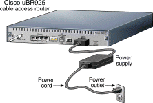
Step 2 Connect the plug end of the power cord into the other end of the power supply.
Step 3 Connect the prong end of the power cord to an AC power outlet. The Cable Access Router powers on immediately when you connect it to the power outlet.
Step 4 Power on the other devices (computers, telephones) that you plan to connect to the Cisco uBR925 Cable Access Router.
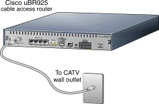
To connect the Cable Access Router to the cable network, use a quality coaxial cable (such as RG-59). If you want to use the same cable outlet for both cable TV and data network services, contact your service provider for information on whether installing a cable splitter is possible.
Step 2 Connect one end of the coaxial cable to the cable TV wall outlet.
Step 3 Connect the other end of the coaxial cable to the connector labeled Cable TV In on the Cable Access Router's rear panel.
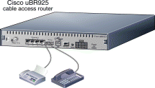
Step 2 Connect the other end of this cable to the analog telephone, modem, or FAX device that has been assigned to this voice port.
Step 3 Repeat these steps for a second analog telephone, modem, or FAX device.
 |
Note  A single-line telephone can be connected to either voice port. A two-line telephone can be connected only to the first (V1+V2) voice port. |
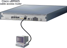
To connect the Cisco uBR925 Cable Access Router to one PC through the Ethernet port, use the yellow Ethernet cable supplied with the unit.
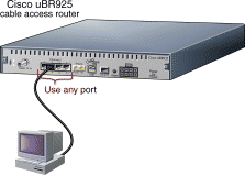
Step 2 Connect the other end of this cable to the Ethernet port on the PC.
Step 3 Repeat to connect as many as four PCs, using straight-through Ethernet cables.
 |
Note  If supported by your service provider, you can also connect an Ethernet hub to the Ethernet port on the Cable Access Router (using a crossover cable), and then connect additional Ethernet devices to the hub (using straight-through cables). |
To connect the Cisco uBR925 Cable Access Router to one PC through the USB port, you need to purchase a host-to-device (type "A" to type "B" connectors, maximum length 5 meters) USB cable. If using a USB hub with your PC, verify that the hub is properly installed before continuing.
Step 2 Plug the other, rectangular end of the USB cable (the type "B" end) into the USB port on the rear panel of the Cable Access Router.
Step 3 Windows automatically detects installation of a new USB device and begins its software installation process. Insert the Cisco Cable CPE USB Driver CD (provided with the unit) in the PC's CD-ROM drive and follow the prompts.
When the Cisco uBR925 Cable Access Router is connected and powered on, it performs a series of self-tests and then automatically configures itself for the cable network.
At the start of initialization, the LEDs on the Cable Access Router light briefly, then turn off. The following events occur during initialization:
1. Various LEDs come on during the self-test to display progress and error codes.
2. The OK LED blinks as the Cable Access Router loads the Cisco IOS software.
3. After the Cisco IOS software loads, the Cable Access Router registers with the service provider and begins network communications.
4. After the Cable Access Router comes online, the OK LED turns on solid.
After initialization, the LEDs light, as shown in the following table, to indicate that the Cable Access Router is operational.

| LED | Function |
|---|---|
OK | On = System OK |
1, 2, 3, 4 | On = Ethernet cable connected and link up |
USB | On = USB cable connected, link up |
CATV ACT | Blink = Coaxial cable activity |
CATV LINK | On = Coaxial cable connected, link up |
V OK1 | On = VOIP2 system enabled and operating OK |
V11 | On = Call in progress (voice port 1) |
V21 | On = Call in progress (voice port 2) |
DS3 | On = Locked to DS channel |
US4 | On = Upstream communication with the CATV headend |
DSNR5 | On = Receiving good DS signal |
MSG | Defined by service provider |
UPS | Reserved for future use |
| 1LEDs are operational only when the Cable Access Router is enabled to carry voice traffic. 2VOIP = Voice over IP 3DS = Downstream 4US = Upstream 5DSNR = Downstream Signal-to-Noise Ratio |
Check the LEDs on your Cable Access Router to verify that it is properly connected:
To verify Internet connectivity, start the web browser software on your PC and connect to a web site of your choice, or try the Cisco.com web site:
If you can access a web page, your installation is successful. If you cannot access a web page, check for the following possible causes:
If the above steps do not help, see the additional troubleshooting steps in the Cisco uBR925 Cable Access Router User Guide. If you still cannot get a connection, contact your service provider for assistance.
![]()
![]()
![]()
![]()
![]()
![]()
![]()
![]()
Posted: Sun Jul 1 00:31:37 PDT 2001
All contents are Copyright © 1992--2001 Cisco Systems, Inc. All rights reserved.
Important Notices and Privacy Statement.