|
|

This Quick Start card describes how to connect the Cisco uBR905 cable access router to the cable TV (CATV) network and to one or more PCs. For more details, see the Cisco uBR905 Hardware Installation Guide, available on the Cisco Connection Online (CCO) website at http://www.cisco.com.

To connect the Cisco uBR905 cable access router to the CATV network, you will need a quality coaxial cable (such as RG-59). If you want to use the same CATV outlet for both cable TV and cable network services, you will also need a coaxial cable splitter, available from your service provider.
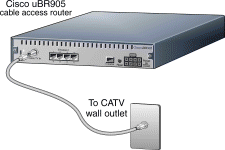
1. Locate the coaxial cable TV wall outlet. 
2. Connect one end of the coaxial cable to the cable TV wall outlet.
3. Connect the other end of the coaxial cable to the connector labeled Cable TV In on the cable access router's rear panel.
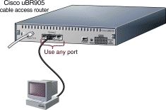
To connect the Cisco uBR905 cable access router to one PC, use the yellow Ethernet cable supplied with the unit. For each additional PC, you will need an additional straight-through Ethernet cable with RJ-45 connectors. 
1. Connect one end of the Ethernet cable into one of the four Ethernet ports (labeled 1, 2, 3, and 4) on the cable access router's rear panel.
2. Connect the other end of this cable to the Ethernet port on the PC.
3. Repeat Step 1 and Step 2 for each additional PC. The cable access router contains four Ethernet ports to connect directly to four PCs.

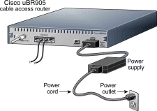
1. Connect the provided black power supply to the eight-pin black power connector on the cable access router's rear panel.
2. Connect one end of the power cord to the power supply and the other end of the power cord to a grounded AC power outlet. The cable access router powers on immediately when you connect it to the power outlet.
3. If the PCs connected to the cable access router are not powered on, turn them on now.
4. Power on all other equipment and wait for the devices to complete startup.

When the Cisco uBR905 cable access router is connected and powered on, it performs a series of self-diagnostics and then automatically configures itself for the CATV network.
At the start of initialization, most of the LEDs (lights) on the cable access router light briefly, then turn off. The following events occur during initialization:
1. Various LEDs come on during the self-test to display progress and error codes.
2. The OK LED blinks as the cable access router completes its self-tests. After the self-tests complete, the OK LED turns on solid.
3. The cable access router registers with the service provider and begins communicating with the CATV network.
4. After initialization, the OK, LINK, DS, US, and DSNR LEDs come on, as shown in the following table, to indicate that the cable access router is operational.

| LED | Description | Function |
|---|---|---|
OK | System status | On = System OK |
CATV ACT | Cable activity | Blink = Cable activity |
CATV LINK | Cable link | On = Link up |
1,2,3, or 4 | Ethernet 1,2,3, or 4 | On = Link up |
MSG | Message | Use is defined by the service provider |
DS | Downstream LED | On = Locked to downstream channel (from headend to PC) |
US | Upstream LED | On = Communication on the upstream (from PC to headend) |
DSNR | Downstream signal-to-noise ratio LED | On = Receiving good downstream signal |

Check the LEDs on your cable access router to make sure that it is properly connected:
To verify Internet connectivity, start the web browser software on your PC and connect to a web site of your choice, or try the Cisco Connection Online (CCO) web site at:
If you can access a web page, your cable access router installation is complete.
If you cannot access a web page, check for the following possible causes:
If you still cannot get a connection, contact your service provider for assistance.

The following safety instructions must be followed when installing the cable access router. Failure to install the unit in accordance with these instructions will invalidate the agency approvals for the Cisco uBR905 cable access router.
For more information and additional safety information and warnings, see the Cisco uBR905 Cable Access Router Hardware Installation Guide, available on CCO (http://www.cisco.com) and the documentation CD-ROM. To locate this document on CCO, click Technical Documents, then Documentation Home Page, then Broadband Cable Solutions, and then Cisco uBR900 Series Cable Access Routers.
![]()
![]()
![]()
![]()
![]()
![]()
![]()
![]()
Posted: Thu Oct 10 07:56:05 PDT 2002
All contents are Copyright © 1992--2002 Cisco Systems, Inc. All rights reserved.
Important Notices and Privacy Statement.