Part Number: OL-0805-02 June 11, 2001 Cisco IOS Release 12.1(5)XU2
This feature module describes the Cisco CVA120 Series Cable Voice Adapters, its major benefits, and how to configure it. This document includes the following major sections:
The Cisco CVA120 Series Cable Voice Adapters is a residential voice-enabled cable modem that provides high-speed data and voice services to home offices and homes over an Internet Protocol (IP). The Cisco CVA120 Series Cable Voice Adapters can deliver data at speeds exceeding analog dial up or Integrated Services Digital Network (ISDN) lines. The supported telephony features allow the Multiple Service Operator (MSO) to provide primary line voice service and secondary line service, using a single coaxial cable connection.
The Cisco CVA120 Series Cable Voice Adapters functions at its most basic level as a cable modem—a modulator/demodulator that provides high-speed network access on the cable television system to residential and small office/home office (SOHO) subscribers.
The Cisco CVA120 Series Cable Voice Adapters can optionally provide Voice over IP (VoIP) services, allowing subscribers to make telephone, modem, and fax calls over TCP/IP networks such as the Internet. These calls can be made to other VoIP devices, or to telephone, modem, or fax devices on the regular telephone network (the Public Telephone Switched Network, commonly known as PTSN). Custom class features such as 3-way calling, caller id, call return, and distinctive ringing are supported.
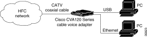
The Cisco CVA120 Series Cable Voice Adapters is equipped with both an Ethernet port and USB port. An optional uninterruptible power supply (UPS) can also provide power to the unit when the main AC-input power supply fails. The cable voice adapter is also designed to configure easily after installation by automatically registering itself on the network.
Cisco CVA120 Series Cable Voice Adapter Models
The Cisco CVA120 Series Cable Voice Adapter is available in two models, depending on the cable networking standard that is being used:
The Cisco CVA122 Cable Voice Adapter supports the DOCSIS standard, which was developed with service providers to ensure that any DOCSIS-certified cable modem can interoperate with any bidirectional, DOCSIS-qualified CMTS. The DOCSIS standard supports the North American National Television Systems Committee (NTSC) channel plan, with 6 MHz channel widths, a downstream range of 88 to 860MHz, and an upstream range of 5 to 42 MHz.
The Cisco CVA122E Cable Voice Adapter supports the EuroDOCSIS standard, which is almost identical to the DOCSIS standard, except that it supports the European Phase Alternating Line (PAL) and Systeme Electronique Couleur Avec Memoire (SECAM) channel plans, with 8 MHz channel widths, a downstream range of 88 to 860MHz, and an upstream range of 5 to 65 MHz.
Note Information about DOCSIS and EuroDOCSIS requirements and current specifications are available
at the CableLabs web site at http://www.cablelabs.com.
Both models of the Cisco CVA120 Series Cable Voice Adapter feature one F-connector interface to the cable system, one RJ-45 (10BASE-T Ethernet) hub port, one USB device port, and two RJ-11 analog voice ports. The USB interface enables the cable voice adapter to connect to a PC with a USB interface, without having the user to open the unit and install an Ethernet network interface card (NIC). If supported by the PC and service provider, PCs can be connected to the cable voice adapter using both the Ethernet and USB interfaces.
Note Unless otherwise indicated, the terms Cisco CVA120 Series Cable Voice Adapter and cable voice
adapter refer to both the Cisco CVA122 Cable Voice Adapter and Cisco CVA122E Cable Voice
Adapter.
The Cisco CVA120 Series Cable Voice Adapter uses its cable interface to connect to the CMTS over the Hybrid/Fiber Coax (HFC) cable system. A personal computer (PC) connects to the Cisco CVA120 Series Cable Voice Adapter through either the Ethernet or USB interface. The Cisco CVA120 Series Cable Voice Adapter then provides Internet access by forwarding traffic between the PC and the CMTS. Subscribers can use the Cisco CVA120 Series Cable Voice Adapter to create high-speed, permanent access to the Internet, without the need for telco-based services such as leased lines.
If supported by the service provider, the Cisco CVA120 Series Cable Voice Adapter can connect to multiple PCs by attaching a PC to each interface (Ethernet and USB). In addition, the Cisco CVA120 Series Cable Voice Adapter's Ethernet interface can connect to an Ethernet hub, and multiple computers can then be connected to the hub.
Note You can connect the Cisco CVA120 Series Cable Voice Adapter to only one PC using the USB port
because the cable voice adapter acts as a USB peripheral device. The cable voice adapter can also
connect to a USB hub, which connects multiple peripherals to one PC, but the USB hub cannot
connect multiple PCs to the cable voice adapter.
Bridging Operations
The Cisco CVA120 Series Cable Voice Adapter provides IP bridging for one or more PCs and other customer premises equipment (CPE) when acting as a DOCSIS/EuroDOCSIS-compliant cable modem. In bridging mode, traffic from the cable voice adapter's Ethernet and USB interfaces is transparently forwarded on to the cable interface for transmission to the CMTS. Similarly, the cable voice adapter receives traffic on the cable interface and forwards it to the PCs attached to the Ethernet and USB interfaces.
Note In bridging mode, the PCs must be assigned IP addresses in the same subnet as the CMTS. Typically,
a Dynamic Host Configuration Protocol (DHCP) server at the headend automatically assigns the IP
addresses to each PC that is authorized to connect to the Cisco CVA120 Series Cable Voice Adapter.
You can connect a PC directly to the Ethernet port or to the USB port. You can connect a PC to both the Ethernet and USB ports, if this configuration is supported by the service provider.
In bridging mode, if only one PC is connected to both the Ethernet and USB interface ports, the cable voice adapter learns which port is in operation first, puts that MAC address in the bridge table, and forwards traffic from that port to the cable interface. If CPE devices are connected to both the Ethernet and USB ports, both ports are active. In this case the first CPE device that generates an Address Resolution Protocol (ARP) request that maps its IP address to a MAC address is put into the bridge table first and that CPE device will have its traffic forwarded first.
Also, if supported by the service provider, you can connect an Ethernet hub directly to the Ethernet port and then connect multiple PCs to the hub. In bridging mode, the Cisco CVA120 Series Cable Voice Adapter supports a maximum 254 PCs, depending on the maximum number allowed by the CMTS.
By default, one PC is supported for each Cisco CVA120 Series Cable Voice Adapter. This PC can be connected to either the Ethernet port or the USB port. If two PCs are connected to each port, then only the first PC that is discovered is allowed to access the network. The service provider can change this limit by changing the MAX CPE parameter in the DOCSIS configuration file. However, the CMTS at the headend can also enforce its own limit on CPE devices, and the CMTS limit overrides the MAX CPE parameter. So if the headend allows only one PC per cable voice adapter, subscribers can connect only one PC to the cable voice adapter, even if the MAX CPE parameter is set to the maximum value of 254.
NoteFor better network performance, Cisco recommends a maximum limit of
16 CPE devices; this recommended maximum might be less depending on the services that the
subscriber has purchased.
Figure 1 Cisco CVA120 Series Cable Voice Adapter in a Bridging Configuration
Note All Cisco IOS releases that support the Cisco CVA120 Series Cable Voice Adapter support basic
DOCSIS/EuroDOCSIS connectivity that provides both high-speed Internet data access and VoIP
connectivity.
The Cisco CVA120 Series Cable Voice Adapter ships from the factory with a Cisco IOS software image stored in nonvolatile Flash memory that supports DOCSIS/EuroDOCSIS-compliant IP bridging data operations.
Voice Operations
The Cisco CVA120 Series Cable Voice Adapter supports Voice over IP (VoIP), which transmits voice, modem, and fax calls over a TCP/IP network such as the Internet. Depending on the services purchased from the cable service provider, subscribers can place and receive calls without using the local exchange carrier.
The cable voice adapter contains two voice ports, which support two simultaneous voice, modem, and fax calls. You can connect a single-line analog telephone, fax, or modem device to each voice port, or you can connect a dual-line telephone device to the first voice port.
You can also connect multiple telephones, modems, and fax devices to each of the voice ports. However, the multiple telephones act as extensions to each voice line, so that only one call at a time can be made per voice port.
Note The Cisco CVA120 Series Cable Voice Adapter supports only analog Foreign Exchange Station
(FXS) telephone, modem, and fax devices. You cannot connect Foreign Exchange Office (FXO)
devices, such as a PBX, to the cable voice adapter voice ports.
Voice signals are packetized and transported in compliance with the following protocols:
H.323v2—Second version of an International Telecommunications Union (ITU) standard that specifies call signaling and control protocols for an IP data network.
Simple Gateway Control Protocol (SGCP) Version 1.1—A signaling protocol under review by the Internet Engineering Task Force (IETF).
Media Gateway Control Protocol (MGCP) Version 0.1—A proposed IETF voice control protocol intended to eventually supersede the existing SCGP 1.1 protocol.
Note The Cisco CVA120 Series Cable Voice Adapter supports both H.323 and SGCP/MGCP call controls,
but only one method can be active at a time.
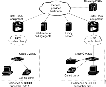
Figure 2 illustrates a broadband cable system that supports VoIP transmission.
Figure 2 Simplified VoIP Network
The CMTS at the headend routes IP telephony calls from the point of origination to the destination, transmitting them along with other traffic (both voice and data). To route voice calls across the local IP network to a destination on the Internet or the Public Switched Telephone Network (PSTN), the Cisco CVA120 Series Cable Voice Adapter and CMTS deploy IP telephony as a local-loop bypass service.
One of the following call routing methods is then used, depending on the protocol being used:
If using H.323v2, the cable voice adapter acts as the H.323v2 gateway that forwards the voice packets to the CMTS, which then sends them to a telephony gatekeeper. The gatekeeper transmits the packets to their ultimate destination.
If using SGCP or MGCP, the Cisco CVA120 Series Cable Voice Adapter acts as the residential gateway that forwards the voice packets to the CMTS, which then connects to the external call agent (SGCP or MGCP) or media gateway controller (MGCP). The call agent or controller determines how to transmit the call across the network to the trunking gateway that is its ultimate destination.
The gateway at the destination typically interconnects the IP network to the Public Switched Telephone Network (PSTN) so that calls can be made to any phone, not just those that are part of the IP telephony network.
Voice calls are digitized, encoded, compressed, and packetized in an originating gateway; and then, decompressed, decoded, and reassembled in the destination gateway. A server maintains subscriber profiles and policy information. See the Cisco service provider voice documentation set if you have Cisco gatekeeper, gateway, or other applicable products.
CautionIn certain countries, the provisioning of voice telephony over the Internet or use of these products may be prohibited and subject to laws, regulations or licenses, including requirements applicable to the use of the products under telecommunications and other laws and regulations. Each customer must comply with all such applicable laws in the country where the customer intends to use the product.
Voice Handling
Typically, voice calls made using the Public Switched Telephone Network (PSTN) require 64 Kbps of bandwidth when transmitted across digital systems. With IP telephony, however, telephone calls can be delivered at rates as low as 8000 bps in a packet format using different compression algorithms. Depending on the Cisco IOS software image being used, the Cisco CVA120 Series Cable Voice Adapter supports the following algorithms:
G.711 A-Law—64000 bps PCM uncompressed encoding, using the A-Law standard used in most of the world except for North America and a few other countries.
G.711 Mu-Law—64000 bps PCM uncompressed encoding, using the Mu-Law standard used in North America and a few other countries.
G.723—5300 bps (ACELP) and 6300 bps (MPMLQ) compressed encoding designed for H.323 voice systems.
G.723 Annex A—5300 bps (ACELP) and 6300 bps (MPMLQ) compressed encoding that provides voice activity detection (VAD) and Comfort Noise Generation (CNG).
G.726 16000 bps, 24000 bps, and 32000 bps compressed adaptive differential PCM (ADPCM) encoding that can handle temporary overloads in the voice traffic.
G.728—16000 bps low-delay variation of code excited linear prediction (CELP) voice compression that provides a good compromise between voice quality and signal compression.
G.729—8000 bps compressed CS-ACELP encoding (default for telephone calls).
G.729 Annex B—8000 bps compressed CS-ACELP encoding using the Annex B format that implements algorithms for voice activity detection (VAD), discontinuous transmission (DTX), and comfort noise generation (CNG).
To achieve acceptable voice quality and reduce network bandwidth usage, several voice processing techniques are used. Digital Signal Processors (DSPs) provide the stream-to-packet and packet-to-stream conversion, and voice processing capabilities. Typical voice processing services include echo cancellation, voice compression, Voice Activity Detection (VAD) or silence compression, and Dual Tone Multi-Frequency (DTMF) tone detection and generation.
Quality of Service Support
Data traffic typically is sent only on a "best effort" basis, and if a packet is lost or delayed, it can be easily retransmitted without significantly affecting the connection. Such delays and losses are unacceptable, however, for real-time traffic such as voice calls.
For this reason, the CMTS and cable voice adapter router assign separate service identifiers (SIDs) for the voice and data traffic flows. Each SID has a separate class of service (CoS) that determines how its traffic flow is handled, allowing voice traffic to have a higher priority than the data traffic.
The CMTS and router can use different traffic shaping mechanisms to ensure that the higher priority voice traffic always has the bandwidth it needs. This allows voice calls (and other real-time traffic) to share the same channel as data traffic, without the quality of the voice calls being degraded by bursty data transmissions.
Note Separate CoS flows are available only when the cable voice adapter is connected to a CMTS that
supports multiple classes of service. In addition, the cable voice adapter's configuration file must
enable multiple classes of service.
The DOCSIS 1.0 specification does not support multiple CoS flows, so when the cable voice adapter
interoperates with a DOCSIS 1.0 CMTS, voice and data traffic are both transmitted on a "best effort"
basis. This can cause poorer voice quality and lower data throughput when calls are being made from
the router's telephone ports.
The Cisco CVA120 Series Cable Voice Adapter supports the following service classes:
The first CoS in the cable voice adapter's configuration file is configured as the "Tiered Best Effort Type Class" and is the default CoS for data traffic. The class has no minimum upstream rate specified for the channel.
This service class is assigned to the primary SID for the cable voice adapter. In addition to being used for data traffic, the cable voice adapter uses this SID for all MAC message exchanges with the CMTS, and for SNMP management traffic.
All traffic using this SID is transmitted on a "best effort" basis, but data traffic within this class can be prioritized into eight different priority levels. Although all data traffic still has lower priority than the voice traffic, this allows certain data traffic (such as MAC messages) to be given higher priority than other data traffic. The CMTS system administrator defines the traffic priority levels and must include the traffic priority fields in the configuration file downloaded to the cable voice adapter.
The cable voice adapter then assigns a secondary CoS for each voice port; each secondary CoS is associated with a secondary SID that is used for the voice port. If using a Cisco IOS image that supports dynamic multi-SID assignment, these secondary SIDs are automatically created when a call is placed from one of the voice ports. When the call terminates, the secondary SID associated with it is deleted. If the Cisco IOS image does not support multi-SIDs, static SIDs are created for each of the voice ports during the power-on provisioning process, permanently reserving the bandwidth needed for the voice traffic.
The CMTS system administrator typically configures these secondary classes of service so that they have higher quality of service (QoS) classes for use by higher priority voice traffic. These classes should also have a minimum upstream data rate specified for the channel to guarantee a specific amount of bandwidth for the corresponding traffic flows. When static SIDs are used, that bandwidth is always reserved for voice calls; however, when dynamic multi-SID assignment is used, that bandwidth is reserved only when the voice calls are active.
H.323v2 Protocol
In architectures using the VoIP H.323v2 protocol stack, the session application manages two call legs for each call: a telephony leg managed by the voice telephony service provider, and the VoIP leg managed by the cable system operator—the VoIP service provider. Use of the H.323v2 protocol typically requires a dial plan and mapper at the headend or other server location to map IP addresses to telephone numbers.
When both legs of the call have been set up, the session application creates a conference between them. The opposite leg's transmit routine for voice packets is given to each provider. The CMTS router passes data to the gateway and gatekeeper. The H.323v2 protocol stack provides signaling using H.225 and feature negotiation using H.245.
Note For more information on using H.323v2, see the document
H.323 Version 2 Support , available on CCO and the Documentation CD-ROM.
To make and receive H.323 calls, the Cisco CVA120 Series Cable Voice Adapter must be configured for the following:
The IP address of the gateway for the destination dialed—In all situations, these IP addresses can be configured statically using the command-line interface (CLI) with voip dial peer group commands. If you are using Cisco gatekeeper products that are running Cisco IOS Release 12.0(5)T or higher images, the cable voice adapter can obtain these addresses dynamically from the gatekeeper using the Registration, Admission, and Status (RAS) protocol.
The telephone numbers of the attached devices—In all situations, these IP addresses can be configured statically using the CLI pots port commands. When using Cisco Network Registrar (CNR) version 3.0 or higher, the IP addresses can be configured with the relay.tcl and setrouter.tcl scripts. If you are using Cisco gatekeeper products that are running Cisco IOS Release 12.0(5)T or higher images, you can obtain these addresses dynamically from CNR. The telephone numbers of attached devices are then sent in DHCP response messages. When the cable voice adapter processes the DHCP response, it automatically creates the pots dial peer for each port, creates the voip dial peer for the RAS target, and starts the H.323v2 RAS gateway support.
Note To support voice configurations using Cisco gatekeeper products with RAS,
Cisco IOS Release 12.0(5)T or higher images with gatekeeper support are required. The headend
must have IP multicast enabled. The cable interface must be designated as the default for RAS to
discover the gatekeeper. The gatekeeper then resolves all dialed destinations sent to the RAS
protocol.
SGCP and MGCP Protocol Stack
The Cisco CVA120 Series Cable Voice Adapter supports the Simple Gateway Control Protocol (SGCP) and Media Gateway Control Protocol (MGCP). Both MGCP and SGCP are signaling protocols that interact with a remote call agent (CA) to provide call setup and teardown for VoIP calls.
Using the call agent, SGCP and MGCP communicate with the voice gateways, dynamically resolving and routing calls. This creates a distributed system that enhances performance, reliability, and scalability while still appearing as a single VoIP gateway to external clients.
The remote call agent also provides the signaling and feature negotiation that would otherwise be provided by the Cisco CVA120 Series Cable Voice Adapter when using the H.323v2 protocol. Similarly, the call agent also provides the mapping of IP addresses to telephone numbers, eliminating the dial plan mapper and static configurations that are required on the router when using the H.323v2 protocol.
The SGCP and MGCP protocols implement the gateway functionality using both trunk and residential gateways. The Cisco CVA120 Series Cable Voice Adapter functions in this mode as a residential gateway with two endpoints.
SGCP and MGCP can preserve Signaling System 7 (SS7) style call control information, and preserve additional network information such as routing information and authentication, authorization, and accounting (AAA) security information. SGCP and MGCP allow voice calls to originate and terminate on the Internet, and allow one end to terminate on the Internet and the other to terminate on a telephone on the PSTN.
IP Routing Operations
The Cisco CVA120 Series Cable Voice Adapter can be configured for IP routing mode. To operate in routing mode, the Cisco CVA120 Series Cable Voice Adapter supports:
Dynamic Host Configuration Protocol (DHCP) Proxy Support
Routing Information Protocol Version 2
Dynamic Host Configuration Protocol Proxy Support
The DHCP proxy support feature is useful in the following situations:
When the Cisco CVA120 Series Cable Voice Adapter is configured for routing mode, an IP address must be assigned to its Ethernet interface. The DHCP proxy support feature allows an external DHCP server to assign an IP address to the Ethernet interface, as opposed to having to assign it manually with the appropriate CLI commands.
When network address translation (NAT) is used, an inside global address pool must be created on the Ethernet interface. The DHCP proxy support feature allows a DHCP server to assign an IP address that automatically creates the NAT address pool, as opposed to manually specifying a static IP address with the appropriate CLI commands.
When configured for DHCP proxy support, during startup the Cisco CVA120 Series Cable Voice Adapter sends a proxy DHCP request to the DHCP server using the Ethernet interface's MAC address. The DHCP server replies with a second IP address that the router assigns to either the Ethernet interface or to the NAT pool, depending on which option was specified.
This feature was introduced in Cisco IOS Release 12.1(1)T.
Routing Information Protocol Version 2
When configured for routing mode, the Cisco CVA120 Series Cable Voice Adapter defaults to using the Routing Information Protocol Version 2 (RIPv2). In routing mode, the Cisco CVA120 Series Cable Voice Adapter automatically configures itself to use the headend's IP address as its IP default gateway. This allows the Cisco CVA120 Series Cable Voice Adapter to send packets not intended for the Ethernet interface to the headend.
RIPv2 routing is useful for small internetworks because it optimizes Network Interface Center (NIC)-assigned IP addresses by defining Variable-Length Subnet Masks (VLSMs) for network addresses, and it allows Classless Interdomain Routing (CIDR) addressing schema.
This feature was introduced in Cisco IOS Release 12.0(4)XI1.
Note The Cisco CVA120 Series Cable Voice Adapter supports only static routes and the RIPv2 routing
protocol.
Upgrading the Software Image
When Cisco IOS images are updated to new releases, the service provider can download them as needed to Cisco CVA120 Series Cable Voice Adapters installed in the field (based on the software licenses purchased). See the Cisco CVA120 Series Cable Voice Adapter Release Notes for a complete list of features and Cisco IOS images that are currently supported.
Service providers can use the Cisco CVA120 Series Cable Voice Adapter's Media Access Controller (MAC) address to uniquely identify each particular unit in the field. The CMTS uses this value to download the proper DOCSIS configuration file to the Cisco CVA120 Series Cable Voice Adapter before beginning operation.
The DOCSIS configuration file can also contain the name of the software image that the Cisco CVA120 Series Cable Voice Adapter should be running. If necessary, the CMTS can also download the proper software image to the cable voice adapter and force it to reboot using the new image.
The download of the DOCSIS configuration file usually takes only a few seconds and is done every time the Cisco CVA120 Series Cable Voice Adapter reboots. The download of the software image can take several minutes to complete, during which time network connectivity is not available. However, the software image must be downloaded only once, until the subscriber needs to be updated with a new or updated image.
Downloading the Cisco IOS Software Image
A Cisco IOS software image is preloaded on the Cisco CVA120 Series Cable Voice Adapter before it is shipped from the factory. However, when updated software images are available, a new Cisco IOS software image can be downloaded to a cable voice adapter installed in the field.
The DOCSIS configuration file can contain a filename for the software image that the Cisco CVA120 Series Cable Voice Adapter runs. If this filename does not match the software image that is currently installed on the cable voice adapter, the cable voice adapter must use the TFTP protocol to download the new image from the server specified in the DOCSIS configuration file.
After the new software image has been downloaded, the Cisco CVA120 Series Cable Voice Adapter resets itself and repeats the entire power-on and provisioning process. This includes downloading the DOCSIS configuration file again. However, because the software image is stored in nonvolatile Flash memory, the cable voice adapter does not have to download it again—the software download occurs only when the service provider specifies a new software image filename in the DOCSIS configuration file.
If the Cisco CVA120 Series Cable Voice Adapter cannot download the new image, it retries the download, as many as 16 attempts. If the cable voice adapter still cannot download the image, it falls back to its previous software image and attempts to go online with that image.
The service provider can also force the Cisco CVA120 Series Cable Voice Adapter to download new software by putting a new image filename in the DOCSIS configuration file and resetting the cable voice adapter. This should be done only after warning the customer that the modem will be offline for several minutes.
Note Because it can take several minutes for this download to be accomplished and for the Cisco CVA120
Series Cable Voice Adapter to repeat its power-on sequence, the desired software image can also be
installed on the router at the warehouse. In this case, the DOCSIS configuration files for each cable
voice adapter should also be updated with the proper filename.
Downloading the Cisco IOS Configuration File
The DOCSIS configuration file uses the type 43 Vendor-Specific Options field to specify that the Cisco CVA120 Series Cable Voice Adapter should download a Cisco IOS configuration file. See the "DOCSIS Configuration File" section for more information.
Note Downloading a Cisco IOS configuration file is not usually required for plug-and-play bridging.
Instead, it is normally used to configure the advanced feature sets.
Upgrading the ROM Monitor Software
The Cisco CVA120 Series Cable Voice Adapter supports both a primary and secondary ROM Monitor (ROMMON). The primary ROMMON is permanently installed, but a secondary ROMMON is upgradable.
After power-on or a hard system reset, the primary ROMMON initially takes control. It then checks for the presence of a secondary ROMMON and if present, verifies that the secondary ROMMON has the correct checksum. If the secondary ROMMON passes these validation tests, the primary ROMMON then passes control to the secondary ROMMON, which then performs the power-on self-test and hardware initialization, and then loads and executes the Cisco IOS software image. Otherwise, the primary ROMMON remains in control and continues the boot process.
This approach allows the secondary ROMMON to be safely upgraded when new software is available. If the file transfer is interrupted, however, or if the new ROMMON software becomes corrupted, the primary ROMMON is still available to boot the cable voice adapter and load the Cisco IOS software image.
To upgrade the secondary ROMMON, use the copy tftp rommon: privileged EXEC command. See the following example:
Router> enable
Router# copy tftp rommon:
Address or name of remote host []? 192.168.100.172
Loading cva120-rboot-mz from 192.168.100.172 (via cable-modem0): !
WARNING...
Do not attempt ROMMON upgrades unless you know what you are doing.
Writing to ROMMON must not be interrupted.
Do not reset the cable modem during this operation.
Do what you can to ensure power to the cable modem is not interrupted.
The cable modem will automatically reloaded after ROMMON
upgrade is successfully completed.
Do you want to continue?[confirm] yes
!!!!!!!!!!!!!!!!!!!!!!!!!!!!!!!!!!!!!!!!!!!!!!!
[OK - 243260/486400 bytes]
If the download of the secondary ROMMON is successful, the cable voice adapter is automatically reloaded to transfer control to the new ROMMON.
Caution If the download of the secondary ROMMON is interrupted by a power cycle, reset, or network interruption, the secondary ROMMON will become corrupted. You must then reset the cable voice adapter to allow the primary ROMMON to take control and reboot the system. After the system has rebooted with the primary ROMMON, you can repeat the download of the secondary ROMMON.
Benefits
Voice Over IP
The multiple service operator (MSO) can offer telephony service to their customers, increasing the MSO's monthly revenues. Customers can receive additional services that are competitively priced with existing services. Since the Cisco CVA120 Series Cable Voice Adapter's software is Cisco IOS-based, it has been proven reliable and feature rich.
USB and Ethernet Ports
Having both USB and Ethernet ports, an MSO can meet the needs of the consumers. A home office consumer can connect multiple PCs or devices to the Cisco CVA120 Series Cable Voice Adapter using the Ethernet plug, and, simultaneously, another family member can use the USB port for a second computer.
Primary Line Support
By offering an Uninterruptible Power Supply (UPS) backup battery, the MSO allows the end user to place calls and receive calls through the Cisco CVA120 Series Cable Voice Adapter even though the power might be out. In the event of a power outage, the customer has phone service for two hours of continuous talk time or eight hours of stand-by. Additionally, the battery signals to the MSO if it needs service, so that the MSO can contact the customer to replace it. The battery also has an LED to alert the end customer if it is running low.
Plug-and-Play Registration
After the Cisco CVA120 Series Cable Voice Adapter is installed, it automatically registers itself on the network and retrieves an IP address. The cable voice adapter is easy to install and installs quickly, thus saving the MSO money.
Switched Interface
Because the USB and Ethernet can be configured as independent switched interfaces, consumers can protect their data. Where one user can access confidential information on a web site, the other user is incapable of interfering with that data. One end user could be on a corporate web site, while the other end user is in a chat room without compromising any corporate confidential information.
Investment Protection for the MSO
The MSO, knowing that Cisco supports the evolving standards, is able to offer new services. As the customer premises equipment (CPE) devices are roughly 50% of the network upgrade costs, the CPE has a software roadmap that supports new features and call controls. The Cisco CVA120 Series Cable Voice Adapter's hardware is designed with additional memory capacity that is adequate to plan for new features and call controls.
Restrictions
Bridging support—The Cisco CVA120 Series Cable Voice Adapter interoperates with DOCSIS cable networks. Cisco IOS Release 12.1(5)XU2 does not support bridging traffic across a non-DOCSIS cable network.
DOCSIS CLI commands removed—Cisco IOS Release 12.1(5)XU2 has removed a number of commands from the CLI to comply with DOCSIS requirements that restrict access to commands that change DOCSIS parameters. DOCSIS management can no longer be done using CLI commands.
IP Address negotiation—The DOCSIS specifications require that a cable modem obtain its IP address at power-on or reset from a DHCP server that is available through the cable interface. For this reason, the Cisco CVA120 Series Cable Voice Adapter defaults to a configuration that uses the ip address docsis command for the cable interface. It is not possible to override this setting by specifying a specific static IP address. To assign a static IP address to the cable voice adapter, configure the DHCP server so that it assigns the desired IP address on the basis of the unit's MAC address.
Using access lists 100, 101, and 102—Access lists 100, 101, and 102 are reserved for DOCSIS use and should never be configured manually on the Cisco CVA120 Series Cable Voice Adapter. Instead, use any access lists 103 through 199.
Using multiple PCs—The MAX CPE parameter in a Cisco CVA120 Series Cable Voice Adapter's DOCSIS configuration file determines how many PCs (or other CPE devices) are supported by the cable voice adapter. The default value for the MAX CPE parameter is 1, which means that only one PC can be connected to the cable voice adapter.
The DOCSIS 1.0 specification states that a CMTS cannot age-out MAC addresses for CPE devices, so the first PC that is connected to the Cisco CVA120 Series Cable Voice Adapter is normally the only one that the CMTS recognizes as valid. If a subscriber replaces an existing PC or changes its network interface card (NIC) to one that has a different MAC address, the CMTS does not allow the PC to come online because this exceeds the maximum number of CPE devices specified by the MAX CPE parameter. A similar result would occur if a user decides to move a PC from one Cisco CVA120 Series Cable Voice Adapter to another.
Related Documents
Refer to the following Cisco documents for related information. The documents can be found online at Cisco Connection Online (CCO) or on the Documentation CD-ROM. You can also order printed copies of most current documents.
Note The list that follows is not all-inclusive. New documents and revisions occur frequently.
Cisco CVA120 Series Cable Voice Adapter
Cisco CVA120 Series Cable Voice Adapter Hardware Installation Guide
Cisco Cable CPE Error Messages
DOCSIS CPE Configurator help
Release Notes for each release of Cisco IOS software for the Cisco CVA120 Series Cable Voice Adapter
CMTS Hardware Installation Publications
Cisco uBR7200 Series Universal Broadband Router Hardware Installation Guide
Cisco uBR7200 Series Universal Broadband Router Software Configuration Guide
Cisco uBR7200 Series Universal Broadband Router Cable Modem Card Installation and Configuration
Cisco uBR7200 Series Universal Broadband Router Port Adapter Installation and Configuration
Cisco uBR7200 Series Universal Broadband Router 550-Watt DC-Input Power Supply Replacement Instructions
Cisco uBR7200 Series Universal Broadband Router Subchassis and Midplane Replacement Instructions
Cisco uBR7200 Series Rack-Mount and Cable-Management Kit Installation Instructions
Cisco uBR7200 Series Universal Broadband Router Fan Tray Replacement Instructions
Cisco uBR7200 Series Universal Broadband Router Feature Enhancements
Cisco IOS Publications
Cisco IOS Release 12.1 New Feature Documentation for feature module descriptions on Cisco IOS Release 12.1-based releases
Cisco IOS Release 12.1 Configuration Guides and Command References for task and command descriptions on Cisco IOS Release 12.1-based releases
Note Use the Cisco IOS Command Reference Master Indexes to obtain document pointers for specific
software release feature sets and commands.
Configuration Editor and Network Management Publications
Cisco Cable Configuration Guide for information on the Cisco Network Registrar (CNR) product
CiscoView: Internetworking Device Monitoring and Management
Cable Modem to Customer Premise Equipment Interface Specification (SP-CMCI-I03-991115)
Radio Frequency Interface Specification (SP-RFI-I05-991105)
USB CM Interface Acceptance Test Plan (TP-USBATP-D01-990910)
Information about these specifications is available at the CableLabs web site at http://www.cablelabs.com.
MIBs
The Cisco CVA120 Series Cable Voice Adapter supports the following MIBS:
Radio Frequency Interface MIBs—These MIBs are for DOCSIS-compliant radio frequency interfaces in cable modems and CMTS. This MIB includes support for the MIB attributes defined in RFC 2670.
Cable device MIBs—These MIBs are for DOCSIS-compliant cable modems and CMTS to record statistics related to the configuration and status of the cable modem. These MIBs include support for the MIB attributes defined in RFC 2669.
Note The Cable Device MIB is very similar to the RFI MIB in that both allow access to
cable-related statistics. However, the Cable Device MIB provides statistics on the cable
modem, and the RFI MIB provides statistics on the radio frequency transmissions over the
cable television line.
Cisco standard MIBs—These MIBs are common across most of Cisco's router platforms. If your network management applications are already configured to support other Cisco routers, such as the Cisco 2600 series or Cisco 7200 series, no further configuration is needed unless the version of Cisco IOS software being used has updated these MIBs.
CISCO-PRODUCT-MIB
CISCO-SYSLOG-MIB
CISCO-FLASH-MIB
BRIDGE-MIB
IF-MIB
CiscoWorks/CiscoView support
SNMP standard MIBs—Required by any agent supporting SNMPv1 or SNMPv2 network management
Uninterruptible Power Supply (UPS) and Power MIBs—These MIBs describe the Cisco CVA120 Series Cable Voice Adapter's onboard environmental monitor, which includes information about the status of the UPS and the power supply. The power and UPS attributes are described in the table, ciscoEnvMonSupplyStatusTable. To send a trap or interrupt request whenever the cable voice adapter switches between its onboard AC power supply and the UPS, set the ciscoEnvMonEnableRedundantSupplyNotification attribute to "true" to enable the ciscoEnvMonRedundantSupplyNotification trap.
Cable-specific MIBs—These MIBs provide information about the cable interface and related information on the Cisco CVA120 Series Cable Voice Adapter. They include both DOCSIS-required MIBs and Cisco-specific enterprise MIBs. If your network management applications have not already been configured for the cable voice adapter, these MIBs must be loaded.
Table 1 shows the cable-specific MIBs that are supported on the Cisco CVA120 Series Cable Voice Adapter.
Table 1 Supported MIBs for the Cisco CVA120 Series Cable Voice Adapter
This module describes generic objects for the Layer 3 network interface sublayers. This MIB is an updated version of MIB-II's if table, and incorporates the extensions defined in RFC 1229.
This module describes the DOCSIS-compliant Radio Frequency (RF) interfaces in cable modems and cable modem termination systems, as described in RFC 2670.
This module extends the DOCSIS standard RFI MIB (DOCS-IF-MIB) with Cisco-specific extensions, such as QoS attributes and connection status and other information regarding the cable modems and CPE devices supported by the CMTS.
This module was previously known as the CABLE-DEVICE-MIB and contains cable-related objects for DOCSIS-compliant cable modems, as specified in RFC 2669 .
USB-MIB.my
This module describes the cable voice adapter's Universal Serial Bus (USB) interface and is based on an IETF draft (draft-dolnik-usb-mib-02.txt), which is available on the IETF web site at http://www.ietf.org/internet-drafts/.
Before going to a subscriber site to install the Cisco CVA120 Series Cable Voice Adapter, verify that the following have been done:
Ensure that a coaxial cable connection is run from the cable TV trunk to the subscriber building or residence.
Note Cisco recommends that a dedicated (new) CATV cable drop be run from the grounding block
directly to the Cisco CVA120 Series Cable Voice Adapter. If such a drop is not available,
careful qualification of existing cable is often necessary. Cable ground should be connected
to the grounding system of the building or residence as close to the point of cable entry as
practical and according to the local and national electrical regulations (for the United States,
see the National Electrical Code Section 820-40 guidelines for proper grounding).
Verify that each subscriber site is characterized at the headend to support upstream transmission, and meets DOCSIS upstream and downstream RF requirements. Observe procedures in the NCTA Recommended Practises for Measurements on Cable Television Systems. Also see the "Cabling" section of the Cisco CVA122 Cable Voice Adapter Hardware Installation Guide.
Some sites specify that high pass filters must be installed on every tap drop that does not carry upstream data, voice, or IPPV services.
Note Installing a high pass filter between the Cisco CVA120 Series Cable Voice Adapter and the
headend will prevent the cable voice adapter from connecting to the headend.
Ensure that all required headend routing and network interface equipment is installed, configured, and operational. Ensure that DHCP, Cisco IOS images, and configuration files have been created and pushed to appropriate servers so that each Cisco CVA120 Series Cable Voice Adapter, when initialized, can transmit a DHCP request, receive an IP address, obtain TFTP and TOD server addresses, and download a configuration file (and updated software image) in compliance with DOCSIS and the procedures in place for your network.
Ensure that each subscriber site meets the operating requirements specified in the "Site Requirements" section of the Cisco CVA122/CVA122E Hardware Installation Guide.
Ensure that all supported equipment at a subscriber site—PCs, telephones, modems, fax devices, and Ethernet hub—is installed and operational. Ensure telephones at subscriber sites support touch-tone (DTMF) dialing.
Verify that all PCs at all subscriber locations meet the minimum computing requirements. If you are using USB connectivity, verify that the USB driver software has been installed; otherwise, verify that Internet connectivity is set for the Ethernet interface. See the "PC Subsystem" section of the Cisco CVA122/CVA122E Cable Voice Adapter Hardware Installation Guide for procedures to verify TCP/IP and DHCP PC settings when onsite.
Each service provider has its own recommendations and requirements for the CPE devices that are connected to the network. However, at the very minimum a PC should meet the requirements listed in Table 2.
Table 2 PC Minimum Requirements for the Cisco CVA120 Series Cable Voice Adapter
24 MB (Windows 98 and Windows 98SE), 32MB (Windows Millennium), 128 MB (Windows 2000)
Internet Software
Internet browser
Internet browser
Networking Hardware
Ethernet network interface card (NIC)
USB-capable computer
Networking Cable
Straight-through 10Base T Ethernet cable with RJ-45 connectors2
Host-to-device USB cable (type "A" to type "B")
Networking Software
Ethernet software driver and TCP/IP networking software (typically supplied with the Ethernet network card)
USB software driver2 and TCP/IP networking software
Configuration
DHCP enabled ("Obtain an IP address automatically")
DHCP enabled ("Obtain an IP address automatically")
1 The service provider might support other types of PCs and CPE devices for network connectivity. At the minimum, these CPE devices must meet the following requirements: 10Base T Ethernet connectivity, TCP/IP networking software, and the ability to obtain an IP address using the DHCP protocol.
2 Supplied with the Cisco CVA120 Series Cable Voice Adapter.
Ensure that you bring sufficient cables to connect all devices at all subscriber locations. For simultaneous TV and computer usage at a subscriber site, obtain cable splitters and directional couplers as appropriate to install when you install the Cisco CVA120 Series Cable Voice Adapter.
The Cisco CVA120 Series Cable Voice Adapter automatically obtains its IP address from the headend DHCP server at power-up. Typically, the PCs at the subscriber site are also configured to use DHCP to obtain their IP addresses. If this is not the case, obtain the static IP addresses for each PC from the applicable system administrator, along with the appropriate gateway and DNS information.
If the cable voice adapter is being configured for VoIP services, obtain the phone numbers and IP addresses that the service provider has assigned to each of the voice ports on the Cisco CVA120 Series Cable Voice Adapter.
Environmental
Follow the operating and nonoperating environmental site requirements for operation of the Cisco CVA120 Series Cable Voice Adapter, as specified in the Cisco CVA122/CVA122E Cable Voice Adapter Hardware Installation Guide.
Power
Follow the recommendations for power supply and power cord described in the Cisco CVA122 Cable Voice Adapter Hardware Installation Guide. Verify that the power source is within the values outlined in Appendix A of the Cisco CVA122/CVA122E Cable Voice Adapter Hardware Installation Guide.
Cabling
Follow the recommendations for radio interference, coaxial cable quality, and distance limitations described in the "Cabling" section of the Cisco CVA122/CVA122E Cable Voice Adapter Hardware Installation Guide.
Configuration Tasks
This section describes the tasks that must be done to configure the Cisco CVA120 Series Cable Voice Adapter for normal operation as a DOCSIS-compliant cable modem. Because of DOCSIS regulations and because of the size of most cable modem networks, configuring the cable voice adapter is not normally done manually. Instead, the following configuration files are created and made available to the cable voice adapter on servers running at the headend, so that it can automatically configure itself at system power-on and reset. Each task in the list indicates if the task is optional or required.
DHCP Server Configuration—The Cisco CVA120 Series Cable Voice Adapter obtains its IP address from a DHCP server at system power-on. (required)
DOCSIS Configuration File—The Cisco CVA120 Series Cable Voice Adapter autoconfigures itself at system power-on by downloading a configuration file in the particular format required by the DOCSIS specifications. (required)
Cisco IOS Configuration File and Commands—The Cisco CVA120 Series Cable Voice Adapter can optionally configure itself for additional features by downloading a Cisco IOS configuration file that contains CLI commands to be executed. (required for VoIP operations, IP routing mode, and Network Address Translation (NAT) capability).
DHCP Server Configuration
The DOCSIS specification (SP-RFI-IO5-991105 or later revision) requires that a DOCSIS-compliant cable modem connect to a DHCP server at power-on or reset to establish temporary IP connectivity with the cable network. This enables the cable modem to download the additional configuration information needed to establish a permanent connection with the headend and cable network.
The DHCP server can be a CMTS with DHCP server capabilities (such as a Cisco uBR7200 series universal broadband router), or it can be a dedicated server located at the headend. The server can be configured manually for each cable modem, or the server can be part of an automated provisioning system such as Cisco Network Registrar (CNR).
The DHCP server provides the information shown in Table 3 to each cable modem.
Note If the modem fails to obtain any of the information it is seeking, it displays an error messsage. All
such messages are explained in the Cisco Cable CPE Error Messages book, viewable online at
www.cisco.com/univercd/cc/td/doc/product/cable/cab_modm/ubcmerrs.pdf .
Table 3 DHCP Server Parameters
Parameter
Description
IP address for the cable modem's cable interface
This IP address typically is assigned dynamically but the service provider can also statically assign IP addresses on the basis of each modem's MAC address.
Note When the cable voice adapter is in DOCSIS-bridging mode, it automatically assigns this IP address to both the cable and Ethernet interfaces. When the cable voice adapter is in routing mode, it assigns this IP address only to the cable interface; the IP address for the Ethernet interface must be configured separately.
IP subnet mask for the cable modem's cable interface
This subnet mask typically is used for all cable modems using the same downstream, but this depends on the setup of the CMTS network and subscribers' needs.
IP address for the TFTP server
This TFTP server provides the DOCSIS configuration file to the cable modem and is typically a dedicated server located at the headend.
IP address for the DHCP relay agent
A DHCP relay agent is required if the DHCP server is located on a network other than the IP address assigned to the cable modem's cable interface. The DHCP relay agent is also used if the DHCP server is providing IP addresses to the CPE devices that are connected to the cable modem and the CPE devices are on a subnet other than the cable modem.
Complete filename for the DOCSIS configuration file
This is the filename for the DOCSIS configuration file that the cable modem should download from the TFTP server.
IP address for one or more time of day (ToD) servers
The cable modem uses the ToD server to get the current date and time so that it can accurately timestamp its SNMP messages and error log entries.
One or more IP addresses for the gateways that will forward IP traffic from the cable modem
Typically, the CMTS acts as the default gateway for the cable modem.
Note Typically, the DHCP server sets the default gateway for DOCSIS cable modems. When this is done on Cisco routers, the default gateway does not appear in the Cisco IOS configuration file, this indicates that the gateway is being set by the DHCP server and not by the configuration file. To display the default gateway, use the show ip default-gateway command.
One or more IP addresses for System Log (SYSLOG) servers
The cable modem can send its error log messages to the SYSLOG servers, which are optional and typically located at the headend.
After making a successful DHCP request, the cable modem contacts the ToD server to get the current date and time. The cable voice adapter also begins the TFTP download of the DOCSIS configuration file, which is described in the next section, "DOCSIS Configuration File."
Note At this point in the registration process, the DHCP server provides an IP address only for the cable
modem, not for the CPE devices it is connecting to the network.
DOCSIS Configuration File
The DOCSIS specification requires that a DOCSIS-compliant cable modem downloads a DOCSIS configuration file during its power-on or reset sequence. This file must be in the format described in the SP-RFI-IO5-991105 specification (or later revision) and must contain the information shown in Table 4.
Specifies the center frequency (in multiples of 62500 Hz) for the downstream channel to be used by the cable voice adapter. (This parameter does not need to be specified in the configuration file because the cable voice adapter will scan the downstream for available frequencies, but it can be specified to ensure that the cable voice adapter conforms to the provider's channel plan.)
Upstream Channel ID
Specifies channel ID for the upstream channel to be used by the cable voice adapter. (This parameter does not need to be specified in the configuration file because it can be set dynamically by the CMTS during provisioning.)
Network Access Configuration
Determines whether CPE devices attached to the cable modem are allowed access to the cable network. The default is to allow access for CPE devices (which is required for normal operations).
Class of Service
Class of Service ID
Specifies the ID for this class of service (1 through 16).
Maximum Downstream Rate
Specifies the maximum downstream data rate (in bits/sec) allowed for traffic associated with this class of service. (This is a limit, not a guarantee of service.)
Maximum Upstream Rate
Specifies the maximum upstream data rate (in bits/sec) allowed for traffic associated with this class of service. (This is a limit, not a guarantee of service.)
Upstream Channel Priority
Specifies the priority for upstream traffic (0 through 7, where 7 is highest priority).
Minimum Upstream Rate
Specifies the minimum upstream data rate (in bits/sec) that is guaranteed for traffic associated with this class of service.
Maximum Upstream Channel Burst
Specifies the maximum size of burst traffic to be allowed on this upstream channel. The size is specified in bytes, 0 through 65535, where 0 is no limit. If this field is set to a nonzero value, it should be set to at least 1800 so that it is greater than the maximum Ethernet frame size of 1518 plus the associated packet overhead).
Class of Service Privacy Enable
Specifies whether BPI encryption should be enabled on traffic associated with this class of service (1 enables BPI encryption, 0 disables BPI encryption).
Vendor Specific Options
Vendor ID
The three-byte Organization Unique Identifier for the vendor, which is also usually the first three bytes of the cable modem's MAC address. This value is usually expressed as a hexadecimal number. This field should be 00000C for Cisco Systems equipment.
Vendor-Specific Options
Contains any arbitrary values that are defined by the manufacturer of the cable modem. The Cisco CVA120 Series Cable Voice Adapter uses this field to identify the Cisco IOS configuration file that should be downloaded (if any). Arbitrary Cisco IOS commands can also be specified in this field.
SNMP Management
SNMP Write-Access Control and SNMP MIB Objects
Allows the service provider to set arbitrary SNMP attributes on the cable modem. For the Cisco CVA120 Series Cable Voice Adapter, these two fields are typically used to enable SNMP management of the cable voice adapter because SNMP management is disabled by default.
Note If using the Cisco DOCSIS Cable Modem Configurator tool, you can enable SNMP management by filling in the IP address for the SNMP manager. The Configurator tool then prepares the proper MIB objects to enable SNMP access.
Baseline Privacy Interface Configuration
Authorize Wait Timeout
Specifies the retransmission interval, in seconds, of Authorization Request messages from the Authorize Wait state. Valid values are 2 through 30 seconds.
Reauthorize Wait Timeout
Specifies the retransmission interval, in seconds, of Reauthorization Request messages from the Authorize Wait state. Valid values are 2 through 30 seconds.
Authorization Grace Timeout
Specifies the grace period for re-authorization, in seconds. Valid values are 1 through 1800 seconds.
Operational Wait Timeout
Specifies the retransmission interval, in seconds, of Key Requests from the Operational Wait state. Valid values are 1 through 10 seconds.
Rekey Wait Timeout
Specifies the retransmission interval, in seconds, of Key Requests from the Rekey Wait state. Valid values are 1 through 10 seconds.
TEK Grace Time
Specifies the grace period for re-keying, in seconds. Valid values are 1 through 1800 seconds.
Authorize Reject Wait Timeout
Specifies how long, in seconds, a cable modem waits in the Authorize Reject Wait state after receiving an Authorization Reject. Valid values are 60 through 1800 seconds.
Customer Premises Equipment
Maximum Number of CPEs
Determines the maximum number of PCs and other CPE devices that can use the cable modem to connect to the cable network. The default value is 1. The Cisco CVA120 Series Cable Voice Adapter supports a maximum number of 254 CPE devices, but the CMTS can also impose its own limit on the number of CPE devices.
CPE Ethernet MAC Address
Configures the cable modem with the MAC addresses for one or more CPE devices that are allowed to connect to the cable network. Entering values in this field is optional because the cable modem can learn the MAC addresses of CPE devices dynamically, up to the maximum allowable number. However, DOCSIS cable modems give priority to the CPE devices whose MAC addresses are in the configuration file.
Software Upgrade
TFTP Software Server IP Address
Specifies the IP address for the TFTP server that will provide software images. This server does not necessarily have to be the same TFTP server that provided the DOCSIS configuration file.
Software Image Filename
Specifies the fully qualified path name for the software image that the cable modem should be running. If necessary, the cable modem uses TFTP to download this image from the software server.
Miscellaneous
Concatenation Support
Specifies whether the cable modem supports DOCSIS 1.1 concatenation of upstream packet requests.
Use RFC2104 HMAC-MD5
Specifies the algorithm used to compute the CMTS Message Integrity Check (MIC). If yes, the HMAC-MD5 algorithm specified in RFC 2104 is used; otherwise, the algorithm specified by RFC 1321 is used. (The algorithm used must match the one used on the CMTS.)
Note Because the RFC 1321 algorithm can be reversed, Cisco strongly recommends the use of only the more secure HMAC-MD5 algorithm.
1 The DOCSIS configuration file also contains fields for one-way cable modems that use telco-return, but these fields do not apply to the Cisco CVA120 Series Cable Voice Adapter, which is a two-way cable modem.
Cisco IOS Configuration File and Commands
The DOCSIS configuration file uses the type 43 Vendor-Specific Options field to specify that the cable voice adapter should download a Cisco IOS configuration file. The Cisco IOS configuration file is an ASCII text file that contains the CLI commands needed to configure the Cisco CVA120 Series Cable Voice Adapter for advanced features that are not specified in the DOCSIS configuration file.
Downloading a Cisco IOS configuration file is not normally required for plug-and-play DOCSIS IP bridging. However, downloading a configuration file is required to configure the cable voice adapter for Voice over IP (VoIP) operations.
Table 5 shows the values that are entered in the Vendor-Specific Information Field (VSIF) to download a Cisco IOS configuration file.
Table 5 Downloading a Cisco IOS Configuration File
Field
Value
Subtype
128
Length
(number of characters in the filename)
Filename
Complete filename, including path, for the Cisco IOS configuration file on the TFTP servers specified in the DOCSIS configuration file.
Note The Cisco IOS configuration file can contain only global configuration mode commands, not Privileged EXEC commands.
An optional way of configuring the Cisco CVA120 Series Cable Voice Adapter is to specify individual CLI commands as part of the VSIF field in the DOCSIS configuration file. Table 6 shows the values that are entered to specify a CLI command that should be executed after the cable voice adapter processes the DOCSIS configuration file and comes online.
Table 6 Specifying CLI Commands
Field
Value
Subtype
131
Length
(number of characters in the command)
CLI Command
The ASCII characters of one CLI global configuration command, as you would type it at the CLI prompt. To specify multiple commands, use this option once for each command.
Note You can specify only global configuration mode commands, not Privileged EXEC commands, in this field.
Tip The VSIF option to include CLI commands in the DOCSIS configuration file should be used to specify a very limited number of commands for specialized applications. To perform a more substantial configuration of the cable voice adapter, use VSIF option 128 to download a Cisco IOS configuration file.
Configuration Examples
This section provides the following configuration examples:
The DOCSIS-compliant IP bridging mode configures the Cisco CVA120 Series Cable Voice Adapter for data-only connection to the cable network and Internet. This is the default configuration.
version 12.1
service config
no service pad
service timestamps debug uptime
service timestamps log uptime
no service password-encryption
!
hostname cva120
!
clock timezone - 4
ip subnet-zero
no ip routing
!
voice-port 0
input gain -2
!
voice-port 1
input gain -2
!
interface Ethernet0
ip address negotiated
no ip directed-broadcast
no ip route-cache
bridge-group 59
bridge-group 59 spanning-disabled
!
interface cable-modem0
ip address docsis
no ip directed-broadcast
no ip route-cache
no ip mroute-cache
bridge-group 59
bridge-group 59 spanning-disabled
!
interface USB0
ip address negotiated
no ip route-cache
no ip mroute-cache
arp timeout 0
bridge-group 59
bridge-group 59 spanning-disabled
!
ip classless
no ip http server
no ip http cable-monitor
no service finger
!
!
line con 0
transport input none
line vty 0 4
!
end
This configuration example shows the following requirements for DOCSIS-compliant bridging:
IP routing is disabled.
No IP address is assigned to the cable interface; instead, the ip address docsis command indicates that a DHCP server assigns an IP address to the cable interface. The Ethernet and USB interfaces use the same IP address because the cable voice adapter is acting as a bridge between the different interfaces, making them part of the same IP network. When the cable voice adapter is in DOCSIS-bridging mode, the IP addresses are automatically assigned during the provisioning process.
Configuring for Routing Mode
The Cisco CVA120 Series Cable Voice Adapter must be configured for routing mode to use advanced features. The routing mode is also required if the PCs attached to the cable voice adapter are on a private network or on a different subnet than the subnet used by the CMTS.
The following steps are required to configure routing mode on the Cisco CVA120 Series Cable Voice Adapter:
Disable DOCSIS/EuroDOCSIS-compliant bridging on the cable interface with the no cable modem compliant bridge interface command.
Remove the bridge group on the cable and Ethernet interfaces with the no bridge group interface command.
Configure the RIPv2 routing protocol (or static routes) on the cable and Ethernet interfaces.
To configure the Cisco CVA120 Series Cable Voice Adapter, log in to the router, enter global configuration mode, and enter the following commands:
Command
Purpose
Step 1
cva120(config)# int c 0
Enter interface configuration mode for the cable interface.
Step 2
cva120(config-if)# no cable-modem compliant bridge
Disable DOCSIS/EuroDOCSIS-compliant bridging.
Step 3
cva120(config-if)# no bridge group number
Remove the bridge group.
Step 4
cva120(config-if)# ip address docsis
Configure the cable interface to receive an IP address from the DHCP server.
Step 5
cva120(config-if)# exit
Return to global configuration mode.
Step 6
cva120(config)# int e 0
Enter interface configuration mode for Ethernet 0.
Step 7
cva120(config-if)# no bridge groupnumber
Remove the bridge group.
Step 8
cva120(config-if)# ip address ip-addresssubnet-mask
Enter the Ethernet interface's IP address and subnet mask.
Step 9
cva120(config-if)# exit
Return to global configuration mode.
Step 10
cva120(config)# int usb 0
Enter interface configuration mode for USB 0.
Step 11
cva120(config-if)# no bridge groupnumber
Remove the bridge group.
Step 12
cva120(config-if)# ip address ip-addresssubnet-mask
Enter the USB interface's IP address and subnet mask.
Enable routing on the cable interface's IP network.
Enable routing on the Ethernet interface's IP network.
Enable routing on the USB interface's IP network.
Return to global configuration mode.
Step 16
cva120(config)# no cdp run
(Optional) Disable the Cisco Discovery Protocol (CDP) on the router. CDP is a proprietary protocol for the discovery of Cisco routers running protocols other than TCP/IP; because DOCSIS cable data networks are primarily TCP/IP networks, CDP is not necessary on the cable voice adapter.
Step 17
cva120(config)# ip default-gatewayip-address
Set the default gateway for routing (typically, this is the CMTS).
Step 18
cva120(config)# ip classless
(Optional) Enable the forwarding of packets that are destined for unrecognized subnets to the best supernet route.
Step 19
cva120(config)# ip route 0.0.0.0 0.0.0.0 ip-address
(Optional) Establish a static route so that all packets without an established route are forwarded to the default gateway (typically the ip-address should be the IP address for the CMTS), regardless of any routing metrics.
Step 20
cva120(config-if)# Ctrl-z
Return to privileged EXEC mode.
Step 21
cva120# copy running-config startup-config Building configuration...
Save the configuration to nonvolatile memory so that it will not be lost in the event of a reset, power cycle, or power outage.
Step 22
cva120# show startup-config
Display the configuration file that was just created.
To verify that routing is enabled, enter the show startup-config command. The following example shows a sample configuration file for basic data-only routing mode; the relevant commands are shown in bold.
version 12.1
service config
no service pad
service timestamps debug uptime
service timestamps log uptime
no service password-encryption
!
hostname Router
!
clock timezone - 4
ip subnet-zero
!
voice-port 0
!
voice-port 1
!
interface Ethernet0
ip address 172.16.10.1 255.255.255.0
no ip directed-broadcast
ip rip send version 2
ip rip receive version 2
!
interface USB0
ip address 172.16.20.1 255.255.255.0
no ip directed-broadcast
ip rip send version 2
ip rip receive version 2
!
interface cable-modem0
ip address docsis
no ip directed-broadcast
ip rip send version 2
ip rip receive version 2
no cable-modem compliant bridge
!
router rip
version 2
network 10.0.0.0
network 172.16.10.0
network 172.16.20.0
!
ip classless
no ip http server
no service finger
!
!
line con 0
transport input none
line vty 0 4
!
end
Note The previous configuration assumes that the DHCP server assigns an IP address to the cable interface
that is in the class A private network (10.0.0.0).
Configuring Routing with DHCP Server
When in routing mode, the Cisco CVA120 Series Cable Voice Adapter can act as a DHCP server for the CPE devices it is connecting to the cable network. A service provider then does not have to be concerned about providing IP addresses to all of the PCs at a subscriber's site. Instead, the provider supplies a pool of IP addresses that the cable voice adapter then allocates to the PCs as needed.
Note The Cisco CVA120 Series Cable Voice Adapter must be configured for routing mode to act as a
DHCP server. If in bridging mode, you can configure the router to proxy DHCP client requests to the
DHCP server at the headend by giving the cable helper-address dhcp-server-ip-address host
interface configuration command. (The ip helper-address and ip forward-protocol interface
configuration commands can also be used for this purpose.)
To configure the Cisco CVA120 Series Cable Voice Adapter to act as a DHCP server, log in to the router, enter global configuration mode, and enter the following commands:
Command
Purpose
Step 1
cva120(config)# ip dhcp pool pool-name
Create an address pool for the DHCP server named pool-name and enter DHCP configuration mode.
Specify the network number and subnet mask for the IP address pool. These IP addresses should be part of the subnet provided by the CMTS cable interface. For example, network 10.17.91.0 255.255.255.0 reserves the IP addresses 10.17.91.1-10.17.91.254 for CPE devices.
Step 3
cva120(config-dhcp)# domain-namedomain-name
The domain name that should be assigned to CPE devices (for example, cisco.com).
Step 4
cva120(config-dhcp)# dns-serverip-address
The IP address for the DNS server provided by the service provider that will service the DNS requests from the CPE devices. More than one DNS server can be specified.
Step 5
cva120(config-dhcp)# default-routerip-address
The IP address for the default router for the CPE devices (typically, this is the CMTS). More than one default router can be specified.
Step 6
cva120(config-dhcp)# exit
Return to global configuration mode.
Step 7
cva120# show startup-config
Display the configuration file that was just created.
To verify that the DHCP server is enabled, enter the show startup-config command. A sample configuration file for a Cisco CVA120 Series Cable Voice Adapter acting as a DHCP server is displayed below. The relevant commands are shown in bold.
version 12.1
service config
no service pad
service timestamps debug uptime
service timestamps log uptime
no service password-encryption
!
hostname Router
!
clock timezone - 4
ip subnet-zero
!
ip dhcp pool Clients
network 192.168.100.0 255.255.255.0
domain-name cisco.com
dns-server 192.168.100.17
default-router 192.168.101.1
!
voice-port 0
!
voice-port 1
!
interface Ethernet0
ip address 192.168.100.1 255.255.0.0
no ip directed-broadcast
ip rip send version 2
ip rip receive version 2
!
interface USB0
shutdown
!
interface cable-modem0
ip address docsis
no ip directed-broadcast
ip rip send version 2
ip rip receive version 2
no cable-modem compliant bridge
!
router rip
version 2
network 10.0.0.0
network 192.168.100.0
!
ip classless
no ip http server
no service finger
!
!
line con 0
transport input none
line vty 0 4
!
end
Note The previous configuration assumes that the DHCP server assigns an IP address to the cable interface
that is in the class A private network (10.0.0.0).
NAT/PAT Configuration
All Cisco IOS images for the Cisco CVA120 Series Cable Voice Adapter support both Network Address Translation (NAT) and Port Address Translation (PAT). This allows a private network that is connected to the cable voice adapter to use the same IP address when communicating through the cable interface to the Internet or other public networks.
With the Cisco CVA120 Series Cable Voice Adapter, the "inside" network is the private network connected to the cable voice adapter's Ethernet interface, and the "outside" network is the network accessed through the cable network (such as the Internet or a company Intranet). The inside addresses are translated to an external IP address that is valid in the outside network.
Note NAT/PAT is not typically used for an USB interface because only one computer can be connected
through the USB interface.
The following commands show a typical configuration:
Command
Purpose
Step 1
cva120(config)# ip nat inside source list list-id interface cable-modem0 overload
Enable translation of the inside source addresses—the "inside" addresses are translated before being presented to the "outside" network. The list-id specifies an access-list that defines the IP addresses that will be used, and overload specifies that multiple inside IP addresses can use the same outside IP address (but using different port numbers to unique identify each inside host).
Step 2
cva120(config)# interface Ethernet0
Enter interface configuration mode for the cable voice adapter's Ethernet interface.
Step 3
cva120(config-if)# ip nat inside
Specify that the Ethernet is the "inside" of the NAT/PAT translation.
Step 4
cva120(config-if)# exit
Exit interface configuration mode.
Step 5
cva120(config)# interface cable-modem0
Enter interface configuration mode for the cable voice adapter's cable interface.
Step 6
cva120(config-if)# ip nat outside
Specify that the cable interface is the "outside" of the NAT/PAT translation.
Step 7
cva120(config-if)# exit
Exit interface configuration mode.
Step 8
cva120(config)# access-listlist-id permit any
Create the access list specified by the list-id parameter in the ip nat inside source command. (This particular example specifies that all IP addresses should be accepted; the filter can be as complex as needed to include or exclude any combination of IP addresses.)
Step 9
cva120# copy running-config startup-config Building configuration...
Save the configuration to nonvolatile memory so that it will not be lost in the event of a reset, power cycle, or power outage.
Step 10
cva120# show startup-config
Display the configuration file that was just created.
Note Additional options, such as static IP address translation, are possible when using NAT/PAT. For more
information about the Easy IP and NAT/PAT feature set, see the
Dial-Related Addressing Services documentation, available on CCO and
the Documentation CD-ROM.
The following configuration shows an example of a Cisco CVA120 Series Cable Voice Adapter that performs NAT/PAT translation on all IP addresses connected to the cable voice adapter's Ethernet interface. The external IP address is overloaded so that multiple IP addresses on the internal network can use the same IP address over the cable interface; different port numbers are used to uniquely identify each device on the Ethernet interface. The relevant commands are shown in bold.
version 12.1
no service pad
service timestamps debug uptime
service timestamps log uptime
no service password-encryption
!
hostname cva120
!
!
voice-port 0
input gain -2
!
voice-port 1
input gain -2
!
ip nat inside source list 1 interface cable-modem0 overload
clock timezone - -4
!
!
interface Ethernet0
ip address negotiated
! This example assumes an IP address of "10.1.1.1 255.255.255.0"
ip nat inside
no ip route-cache
bridge-group 59
bridge-group 59 spanning-disabled
!
interface cable-modem0
ip address docsis
ip nat outside
no keepalive
no ip route-cache
bridge-group 59
bridge-group 59 spanning-disabled
!
interface USB0
ip address negotiated
no ip route-cache
no ip mroute-cache
arp timeout 0
bridge-group 59
bridge-group 59 spanning-disabled
!
ip default-gateway 192.168.100.2! This value is set by the DHCP server
ip classless
no ip http server
no ip http cable-monitor
no service finger
ip route 0.0.0.0 0.0.0.0 192.168.100.2
access-list 1 permit any
!
!
line con 0
line vty 0 4
login
!
end
Note This configuration assumes that the DHCP server assigns an IP address to the cable interface that is
in the class C private network (192.168.100.0).
H.323v2 Static Bridging Configuration
The Cisco CVA120 Series Cable Voice Adapter can support voice calls using an H.323v2 static dialing map. This requires the following minimum configuration:
Create a local dial peer for each voice port that will receive incoming calls. This requires configuring each voice port on the cable voice adapter with the phone numbers for the devices attached to those voice ports. The Cisco CVA120 Series Cable Voice Adapter uses these numbers to determine which voice port should receive the call. Typically, the complete phone number or extension is specified for each port. When the cable voice adapter receives an incoming call, all digits in the number are matched and stripped off, and the voice port is connected to the call.
Note The voice ports on the Cisco CVA120 Series Cable Voice Adapter support only FXS devices.
Configure a remote dial peer for each possible destination for outgoing calls. This requires specifying the phone numbers for the destination devices. Use the following guidelines for what numbers to enter:
For a single telephony device, such as a one-line phone or fax machine, enter the complete phone number or extension.
To direct a group of numbers to a specific destination—such as the extensions used on a remote PBX—enter a pattern matching the prefix used for those lines; an asterisk (*) matches any number of digits and a period (.) matches a single digit. For example, "572*" matches any phone numbers starting with 572, but "572." matches only the numbers 5720-5729.
You must also specify the IP address for the destination host that will deliver the call to the telephony device (or if the destination device is an IP telephone, the IP address for that telephone). You can optionally specify an IP precedence level for the type of service (ToS) bits in the IP header to signify that these voice packets should be given higher priority in transit across the IP network.
You can also specify which coding/decoding (codec) algorithm should be used if it is not being done by the CoS.
These functions are done using the dial-peer command, as shown in the following table:
Command
Purpose
Step 1
To configure incoming calls on the voice ports:
cva120(config)# dial-peer voice id-number pots
Repeat this sequence for each voice port.
Specify a unique id-number for this incoming dial-peer and enter dial-peer configuration mode.
Specify the destination IP address or hostname for this dial-peer. This could be the IP address or hostname for either an IP telephone or another router or host providing voice services.
Step 9
cva120(config-dial-peer)# ip precedencenumber
(Optional) Specify an IP packet precedence level (1 through 5) for packets carrying calls to this dial peer (1 through 5, where 5 is the highest precedence for normal IP flows).
(Optional) Specify the codec algorithm to be used for these calls. The default is g729r8 (8Kbps compression; A-Law and Mu-Law are 64Kbps compression); g728 specifies G.728 (16 Kbps compression) and is not available in all images.
Optionally configure the dial peer to support out of band signaling of DTMF tones.
Step 12
cva120(config-dial-peer)# exit
Exit dial-peer configuration mode.
Step 13
cva120# copy running-config startup-config Building configuration...
Save the configuration to nonvolatile memory so that it will not be lost in the event of a reset, power cycle, or power outage.
Step 14
cva120# show startup-config
Display the configuration file that was just created.
Note The ID numbers assigned using the dial-peer voice command must be unique but they are local to
the Cisco CVA120 Series Cable Voice Adapter. These numbers are used only when you configure
each particular dial peer and have no meaning when dialing numbers or routing calls are done.
The following example shows a Cisco CVA120 Series Cable Voice Adapter set up to support bridging and a static H.323 dial map with the following characteristics:
Voice port V1 is connected to a telephony device that receives calls for the number 4123.
Voice port V2 is connected to a telephony device that receives calls for the number 4124.
Outgoing calls to the numbers 6000 through 6999 are routed to the dial peer at IP address 10.1.71.65.
Outgoing calls to the numbers 7000 through 7999 are routed to the dial peer at IP address 10.1.71.75. These calls are sent with an IP ToS precedence of "5" and use the G.711 Mu-law codec algorithm. The commands that set up the H.323v2 dial map are shown in bold:
The Cisco CVA120 Series Cable Voice Adapter supports using the Registration, Admission, and Status (RAS) protocol to allow a remote gatekeeper to translate phone numbers (E.164 addresses) to the IP addresses of specific dial peers. This allows the gatekeeper to maintain a central database of dial peers, so that this information does not have to be entered into static dial maps on every router that is acting as a voice gateway.
The example shown in this section assumes that Cisco Network Registrar (CNR) Version 3.0 or higher is being used as the DHCP server. CNR assigns the E.164 addresses to local voice ports and uses DHCP to define the E.164 addresses-to-port assignments.
The gatekeeper can be a Cisco router, such as the Cisco 3620, with a Cisco IOS image that supports the gatekeeper function. The Cisco CVA120 Series Cable Voice Adapter acts as the H.323v2 gateway and creates the dial peers, starts H.323 RAS gateway support, and registers the E.164 addresses with the gatekeeper. The gatekeeper resolves the remote peers' IP addresses when the cable voice adapter sends a request using RAS.
Note Support for RAS and H.323v2 in Cisco gatekeeper products is found in Cisco IOS Release 12.0(5)T
or higher. Support for multiple classes of service when using Cisco CMTS equipment is found in
Cisco IOS Release 12.0(4)XI or higher.
You must do the following to configure the Cisco CVA120 Series Cable Voice Adapter for dynamic mapping:
Configure the local dial-peers—This is done in the same way as for a static H.323v2 dial map.
Configure the remote dial-peers—This is done in the same way as for a static H.323v2 dial map, except that instead of specifying a target IP address or host name, you specify ras as the target.
Enable the VoIP gateway function using the gateway global configuration command.
Configure the cable modem interface to be the gateway interface.
These functions are done using the commands shown in the following table:
Command
Purpose
Step 1
To configure incoming calls on the voice ports:
cva120(config)# dial-peer voice id-number pots
Repeat this sequence for each voice port.
Specify a unique id-number for this incoming dial-peer and enter dial-peer configuration mode.
Enter whatever commands are needed to configure the cable interface such as IP address, downstream channel, whether DOCSIS-bridging is enabled, and so forth.
Step 14
cva120(config-if)# h323-gateway voip interface
Specify that the cable interface is the H.323 Gateway VoIP interface.
Step 15
cva120(config-if)# h323-gateway voip id gatekeeper-id ipaddrIP-addressport-number
Identify the RAS gatekeeper by specifying its gatekeeper ID (which must match the ID configured on the gatekeeper), its IP address, and the port number which services gateway requests.
Step 16
cva120(config-if)# h323-gateway voip h323-idinterface-id
Specify the H.323 ID for this interface. This ID is any string that uniquely identifies this gateway to the gatekeeper. Typically, this is the gateway's name and domain (such as cva122@cisco.com).
Step 17
cva120(config-if)# h323-gateway voip tech-prefixprefix
(Optional) Specify a technology prefix to identify the type of service this gateway can provide. If more than one service is being provided, give this command for each separate technology prefix. (The prefix is defined at the gatekeeper and can be up to 11 characters long, with the pound sign (#) as the last character.)
Step 18
cva120(config-if)# exit
Exit interface configuration mode.
Step 19
cva120# copy running-config startup-config Building configuration...
Save the configuration to nonvolatile memory so that it will not be lost in the event of a reset, power cycle, or power outage.
Step 20
cva120# show startup-config
Display the configuration file that was just created.
Note For additional information on the gateway configuration commands, see the document
Configuring H.323 VoIP Gateway for Cisco Access Platforms, available
on CCO and the Document CD-ROM.
The following configuration shows a Cisco CVA120 Series Cable Voice Adapter configured for routing mode and using RAS dynamic mapping with the following characteristics:
The cable voice adapter's V1 voice port is connected to a telephone or fax machine with the number 1000, and the V2 voice port is connected to a telephone or fax machine with the number 1001.
Four remote dial-peers are configured, with the numbers 1000, 1001, 2000, and 2001. All use the G.711 Mu-Law CODEC and the RAS protocol is used to resolve their number-address mapping.
The cable interface is configured as the gatekeeper interface, using the gatekeeper named gatekeeper3620 at the IP address 10.1.70.50 and at port 1719. The cable voice adapter identifies itself as the gateway named cva120 with a tech-prefix of 1#.
The commands related to the dial mapping are in bold.
version 12.2
service config
no service pad
service timestamps debug uptime
service timestamps log uptime
no service password-encryption
!
hostname cva120
!
clock timezone - 4
ip subnet-zero
ip host-routing
!
voice-port 0
input gain -2
!
voice-port 1
input gain -2
!
dial-peer voice 1 pots
destination-pattern 1000
port 0
!
dial-peer voice 2 pots
destination-pattern 1001
port 1
!
dial-peer voice 10 voip
destination-pattern 1001
codec g711ulaw
session target ras
!
dial-peer voice 20 voip
destination-pattern 1000
codec g711ulaw
session target ras
!
dial-peer voice 30 voip
destination-pattern 2000
codec g711ulaw
session target ras
!
dial-peer voice 40 voip
destination-pattern 2001
codec g711ulaw
session target ras
!
gateway
!
!
interface Ethernet0
ip address negotiated
no ip directed-broadcast
no ip route-cache
no ip mroute-cache
bridge-group 59
bridge-group 59 spanning-disabled
!
interface cable-modem0
ip address docsis
no ip directed-broadcast
no ip route-cache
no ip mroute-cache
no keepalive
h323-gateway voip interface
h323-gateway voip id gatekeeper3620 ipaddr 10.1.70.50 1719
h323-gateway voip h323-id cva120
h323-gateway voip tech-prefix 1#
bridge-group 59
bridge-group 59 spanning-disabled
!
interface USB0
ip address negotiated
no ip route-cache
no ip mroute-cache
arp timeout 0
bridge-group 59
bridge-group 59 spanning-disabled
!
ip classless
no ip http server
no ip http cable-monitor
no service finger
!
!
line con 0
transport input none
line vty 0 4
!
end
Note This configuration assumes that the DHCP server assigns an IP address to the cable interface that is
in the class A private network (10.0.0.0).
SGCP Configuration
The Cisco CVA120 Series Cable Voice Adapter can use the SGCP protocol for routing voice calls. This transfers the dial mapping to an external call agent, so that the VoIP gateways do not have to be individually configured with the dial mappings.
You must do the following to configure the Cisco CVA120 Series Cable Voice Adapter for a dynamic mapping configuration:
Enable SGCP operation on the Cisco CVA120 Series Cable Voice Adapter.
Specify the SGCP call agent's IP address.
Configure the local dial-peers to be SGCP applications.
Optionally enable the sending of SNMP traps for SGCP.
Note You do not need to configure remote dial-peers when you are using SGCP.
The configuration functions are done using the commands shown in the following table:
Command
Purpose
Step 1
To configure incoming calls on the voice ports:
cva120(config)# dial-peer voice id-number pots
Repeat this sequence for each voice port.
Specify a unique id-number for this incoming dial-peer and enter dial-peer configuration mode.
Step 2
cva120(config)# application SGCPAPP
Specify that this dial-peer is handled as an SGCP application.
Specify the telephone numbers associated with this voice port.
Step 4
cva120(config-dial-peer)# port [ 0 | 1 ]
Specify the voice port that is attached to this telephony equipment: 0 (V1), 1 (V2).
Step 5
cva120(config-dial-peer)# exit
Exit dial-peer configuration mode.
Step 6
cva120(config)# sgcp
Enable SGCP operations on the cable voice adapter.
Step 7
cva120(config)# sgcp call-agentip-address [ port ]
Specify the IP address and optional UDP port number for the SGCP call-agent. If no port number is given, the default of 2427 (the well-known SGCP port number) is used.
Step 8
cva120(config)# snmp-server enable traps xgcp
(Optional) If SNMP management is used for this router, specify that SGCP and related traps be sent to the SNMP manager.
Step 9
cva120# copy running-config startup-config Building configuration...
Save the configuration to nonvolatile memory so that it will not be lost in the event of a reset, power cycle, or power outage.
Step 10
cva120# show startup-config
Display the configuration file that was just created.
The following configuration shows a Cisco CVA120 Series Cable Voice Adapter that uses SGCP for the routing of its voice calls. Two voice ports are defined. The relevant commands are shown in bold.
version 12.1
no service pad
service timestamps debug uptime
service timestamps log uptime
no service password-encryption
!
hostname cva120
!
!
clock timezone - 0 6
ip subnet-zero
no ip routing
ip domain-name cisco.com
ip name-server 4.0.0.32
!
sgcp
sgcp call-agent 10.186.1.36
!
xgcp snmp sgcp
!
!
voice-port 0
input gain -2
!
voice-port 1
input gain -2
!
dial-peer voice 100 pots
application SGCPAPP
destination-pattern 5551212
port 0
!
dial-peer voice 101 pots
application SGCPAPP
destination-pattern 5551213
port 1
!
process-max-time 200
!
interface Ethernet0
no ip directed-broadcast
no ip route-cache
no ip mroute-cache
bridge-group 59
bridge-group 59 spanning-disabled
!
interface cable-modem0
ip address docsis
no ip directed-broadcast
no ip route-cache
no ip mroute-cache
cable-modem downstream saved channel 699000000 27
bridge-group 59
bridge-group 59 spanning-disabled
!
interface USB0
ip address negotiated
no ip route-cache
no ip mroute-cache
arp timeout 0
bridge-group 59
bridge-group 59 spanning-disabled
!
ip classless
no ip http server
no ip http cable-monitor
no service finger
!
line con 0
transport input none
line vty 0 4
login
!
end
MGCP Configuration
The Cisco CVA120 Series Cable Voice Adapter supports the MGCP protocol for routing voice calls. This transfers the dial mapping to an external call agent or to a Media Gateway Controller, so that the VoIP gateways do not have to be individually configured with the dial mappings.
You must do the following to configure the Cisco CVA120 Series Cable Voice Adapter for MGCP routing of voice calls:
Enable MGCP operation on the Cisco CVA120 Series Cable Voice Adapter.
Specify the MGCP call agent's IP address.
Configure the local dial-peers to be MCGP applications.
Optionally specify the MGCP packages to be supported.
Optionally change a number of MGCP parameters.
Note You do not need to configure remote dial-peers when you are using MGCP.
The configuration functions are done using the commands shown in the following table:
Command
Purpose
Step 1
To configure incoming calls on the voice ports:
cva120(config)# dial-peer voice id-number pots
Repeat this sequence for each voice port.
Specify a unique id-number for this incoming dial-peer and enter dial-peer configuration mode.
Step 2
cva120(config)# application MGCPAPP
Specify that this dial-peer is handled as an MGCP application.
Step 3
cva120(config-dial-peer)# port [ 0 | 1 ]
Specify the voice port that is attached to this telephony equipment: 0 (V1), 1 (V2).
Step 4
cva120(config-dial-peer)# exit
Exit dial-peer configuration mode.
Step 5
cva120(config)# mgcp
Enable MGCP operations on the cable voice adapter.
Specify the IP address and optional UDP port number for the MGCP call-agent. If no port number is given, the default is 2427. The default service-type is mgcp, but sgcp can be specified to ignore RSIP error messages.
(Optional) Enables the accurate forwarding of touchtone digits during a voice call. Use codec to specify the G.711 codec or low-bit-rate to specify the G.729 codec. Use a mode of cisco to transmit the tones with the Cisco proprietary method; if the remote gateway is not a Cisco router, use out-of-band instead.
(Optional) Enable IP Type of Services (TOS) for the voice connections, and specify the value for the IP precedence bit (the default IP precedence is 3).
Step 9
cva120(config)# mgcp max-waiting-delayvalue
(Optional) Specify the number of milliseconds to wait after a restart (default of 3000) before connecting with the call agent. If used, these values should be staggered among gateways to avoid having large numbers of gateways connecting with the call agent at the same time after a mass restart.
Step 10
cva120(config)# mgcpmodem passthru { cisco | ca }
(Optional) Enable the transmission and reception of modem and fax data. If the remote gateway is a Cisco router, specify cisco; otherwise, specify ca (default) to allow the data to pass-through the call-agent.
(Optional) Specify that the Cisco CVA120 Series Cable Voice Adapter supports a particular package capability. Give this command multiple times to enable multiple packages. Use this command before using the mgcp default-package command.
(Optional) Change the jitter buffer packet size in milliseconds for MGCP calls, using either an adaptive range or a fixed value. The default is adaptive 60 4 200.
Step 14
cva120(config)# mgcp request retries count
(Optional) Specify the number of times a call request message is transmitted to a call agent before timing out. The default is 3 times.
Step 15
cva120(config)# mgcp request timeouttimeout
(Optional) Specify the number of milliseconds to wait for a response to a request before retransmitting or timing out the request. The default is 500 milliseconds.
Step 16
cva120(config)# mgcp restart-delayvalue
(Optional) Specify the value (in seconds) used in Restart in Progress (RSIP) messages to indicate the delay before the connection is torn down. The default delay is 0 seconds.
Step 17
cva120(config)# mgcp vad
(Optional) Enable Voice Activity Detection (VAD) to turn silence suppression on. The default disables VAD.
Step 18
cva120# copy running-config startup-config Building configuration...
Save the configuration to nonvolatile memory so that it will not be lost in the event of a reset, power cycle, or power outage.
Step 19
cva120# show startup-config
Display the configuration file that was just created.
The following configuration shows a Cisco CVA120 Series Cable Voice Adapter configured in DOCSIS-bridging mode that uses MGCP for controlling its voice calls. The relevant commands are shown in bold.
version 12.2
no service pad
service timestamps debug uptime
service timestamps log uptime
no service password-encryption
!
hostname cva120
!
!
clock timezone - 0 6
ip subnet-zero
no ip routing
ip domain-name cisco.com
ip name-server 10.0.0.32
!
mgcp
mgcp call-agent 10.186.1.36
mgcp modem passthru ca
mgcp package-capability dtmf-package
mgcp package-capability line-package
mgcp default-package line-package
!
xgcp snmp sgcp
!
!
voice-port 0
input gain -2
!
voice-port 1
input gain -2
!
dial-peer voice 100 pots
application MGCPAPP
port 0
!
dial-peer voice 101 pots
application MGCPAPP
port 1
!
process-max-time 200
!
interface Ethernet0
no ip directed-broadcast
no ip route-cache
no ip mroute-cache
bridge-group 59
bridge-group 59 spanning-disabled
!
interface cable-modem0
ip address docsis
no ip directed-broadcast
no ip route-cache
no ip mroute-cache
bridge-group 59
bridge-group 59 spanning-disabled
!
interface USB0
ip address negotiated
no ip route-cache
no ip mroute-cache
arp timeout 0
bridge-group 59
bridge-group 59 spanning-disabled
!
ip classless
no ip http server
no ip http cable-monitor
no service finger
!
!
line con 0
transport input none
line vty 0 4
login
!
end
Command Reference
This section describes the commands for the Cisco CVA120 Series Cable Voice Adapter that are new or changed from the commands described in the Cisco IOS Release 12.1 command reference publications. All other commands used with this feature are documented in the Cisco IOS Release12.1 command reference publications.
To configure the Cisco CVA120 Series Cable Voice Adapter so that it configures its Ethernet interface or Network Address Translation (NAT) address pool with an IP address supplied by the DHCP server, use the cable dhcp-proxy cable interface command. To disable this feature (so that you can then manually assign an IP address to the Ethernet interface or NAT address pool), use the no form of this command.
no cable dhcp-proxy{interface ethernetnumber| natpool-name}
Note This command cannot be used when the Cisco CVA120 Series Cable Voice Adapter is configured for
DOCSIS bridging.
Syntax Description
interface ethernet number
The Ethernet interface to be assigned the static IP address from the DHCP server. (Because the Cisco CVA120 Series Cable Voice Adapter has only one Ethernet interface, the only allowable number is 0).
Note This option should be used only when the Cisco CVA120 Series Cable Voice Adapter is configured for routing mode.
nat pool-name
The name of the NAT pool to be created using the IP address and subnet mask supplied by the DHCP server. (This is equivalent to giving the ip nat poolpool-name start-ip end-ipnetmasksubnetcommand, using the IP address and subnet mask supplied by the DHCP server.)
Defaults
No default behavior or values.
Command Modes
Interface configuration (cable interface only)
Command History
Release
Modification
12.1(1)T
This command was introduced for the Cisco uBR924 cable access router.
12.1(3)XL
Support was added for the Cisco uBR905 cable access router.
12.1(5)XU2
Support was added for the Cisco CVA120 Series Cable Voice Adapter.
Usage Guidelines
This command is useful in the following situations:
When the Cisco CVA120 Series Cable Voice Adapter is configured for routing mode, an IP address must be assigned to its Ethernet interface. Without the cable dhcp-proxy command, this IP address must be a static IP address assigned either by using a Cisco IOS configuration file or by manually entering the necessary interface configuration CLI commands. The cable dhcp-proxy command allows a DHCP server to assign an IP address to the Ethernet interface.
When network address translation (NAT) is used, an inside global address pool must be created on the Ethernet interface. Without the cable dhcp-proxy command, this must be done by specifying a static IP address in the ip nat poolpool-namestart-ipend-ipnetmasksubnet command. The cable dhcp-proxy command allows a DHCP server to assign an IP address that automatically creates the NAT address pool.
When using this option, you must also use the following NAT configuration commands:
Use the ip nat inside interface command to configure the Ethernet interface as the "inside" interface.
Use the ip nat outside interface command to configure the cable interface as the "outside" interface.
Specify the overload option with the ip nat global configuration command because the NAT pool created by the cable dhcp-proxy command contains only one IP address.
After configuring the Cisco CVA120 Series Cable Voice Adapter with the cable dhcp-proxy command, reboot the router. During the DOCSIS provisioning process, the router sends a DHCP client request to obtain an IP address for the cable interface.
The router then sends a proxy DHCP request to the DHCP server using the Ethernet interface's MAC address. The DHCP server replies with a second IP address that the router assigns to either the Ethernet interface or to the NAT pool, depending on which option was used in the cable dhcp-proxy command.
Note When replying to the proxy request for the Ethernet interface, the DHCP server should assign an IP
address on the same network as the CPE devices that are attached to the router's Ethernet interface.
Examples
The following example configures the Cisco CVA120 Series Cable Voice Adapter so that it makes a proxy DHCP request to obtain an IP address for its Ethernet interface:
The following example creates a NAT address pool with the IP address assigned by the DHCP server; this IP address must be in the network attached to the Ethernet address (which in this case is 192.168.100.0).
cva120(config)# ip nat inside source list 1 pool net-208 overload
cva120(config)# interface cable0
cva120(config-if)# ip nat outside
cva120(config-if)# no cable compliant bridge
cva120(config-if)# cable dhcp-proxy nat net-208
cva120(config-if)# exit
cva120(config)# interface ethernet0
cva120(config-if)# ip address 192.168.100.94 255.255.255.0
To enable DOCSIS/EuroDOCSIS-compliant bridging for a cable access router interface at startup, use the cable-modem compliant bridge cable interface configuration command. To disable DOCSIS-compliant bridging (which is required to enable routing mode), use the no form of this command.
cable-modem compliantbridge
no cable-modem compliant bridge
Syntax Description
This command has no arguments or keywords.
Defaults
DOCSIS/EuroDOCSIS-compliant bridging is enabled by default.
Command Modes
Cable interface configuration
Command History
Release
Modification
11.3(4)NA
This command was introduced for the Cisco uBR904 cable access router.
12.0(4)XI1
Support was added for the Cisco uBR924 cable access router.
12.1(1)XD
Support was added for the Cisco uBR914 cable DSU.
12.1(3)XL
Support was added for the Cisco uBR905 cable access router.
12.1(5)XU2
Support was added for the Cisco CVA120 Series Cable Voice Adapter.
Usage Guidelines
It is normally not necessary to enter this command in data-over-cable bridging applications because DOCSIS-compliant bridging is enabled by default. However, to configure the router for full transparent bridging or for routing mode, use the no form of the command and then configure the router as desired using the appropriate CLI commands.
Examples
The following example shows how to enter the cable-modem compliant bridge command for a cable access router interface, starting from global configuration mode:
cva120(config)# interface cable-modem 0
cva120(config-if)# cable-modem compliant bridge
cable-modem voip clock-internal
To enable the Cisco CVA120 Series Cable Voice Adapter's internal clock for VoIP calls, use the cable-modem voip clock-internal cable interface configuration command. To disable the cable voice adapter's internal clock, so that it uses the clock from the cable interface for VoIP calls, use the no form of this command.
cable-modem voip clock-internal
no cable-modem voip clock-internal
Syntax Description
This command has no keywords or arguments.
Defaults
The default is to use the clock from the cable interface for VoIP calls.
Command Modes
Cable interface configuration.
Command History
Release
Modification
12.1(4)T
This command was introduced for the Cisco uBR924 cable access router.
12.1(5)XU2
Support was added for the Cisco CVA120 Series Cable Voice Adapter.
Usage Guidelines
This command enables the cable voice adapter's internal clock, allowing it to make VoIP calls over the Ethernet and USB interfaces even when the cable interface is down or disconnected. If the CMTS is a Cisco uBR7200 series with a Cisco Cable Clock Card, this command disables the use of that clock.
This command can be used when the cable voice adapter is in both DOCSIS IP bridging and routing mode. However, when the cable voice adapter is operating in DOCSIS IP bridging mode, VoIP packets are transmitted out only on the cable interface, so the router must be operating in routing mode to transmit voice packets out the Ethernet and USB interfaces.
Examples
The following example enables the cable voice adapter's internal clock:
cva122(config)# interface cable0
cva122(config-if)# cable-modem voip clock-internal
cva122(config-if)#
dtmf-relay
To configure the Cisco CVA120 Series Cable Voice Adapter so that it transmits Dual-Tone Multifrequency (DTMF) tones as out of band signals during H.323 voice calls, use the dtmf-relay dial-peer voice configuration command. To return to the default configuration (which is to transmit DTMF tones as part of the voice traffic), use the no form of this command.
Forwards DTMF tones using the Real-Time Transport Protocol (RTP) with a Cisco proprietary payload type.
Note RTP is a proprietary Cisco protocol that interoperates only between two Cisco access servers or routers running Cisco IOS images that support the RTP protocol. This typically requires Cisco IOS 12.0(5)T or later releases; see the router's release notes for complete information.
h245-alphanumeric
Forwards DTMF tones using the H.245 Alphanumeric User Input Indication method. This transmits each tone using a fixed duration of 500 milliseconds. Supports tones 0-9, *, #, and A-D.
h245-signal
Forwards DTMF tones using the H.245 Signal User Input Indication method. This transmits each tone using the original duration. Supports tones 0-9, *, #, and A-D.
Defaults
By default, DTMF tones are transmitted inband, as part of the voice traffic.
Command Modes
Dial-peer voice configuration.
Command History
Release
Modification
12.0(7)XR and 12.1(1)T
This command was introduced for the Cisco uBR924 cable access router.
12.1(5)XU2
Support was added for the Cisco CVA120 Series Cable Voice Adapter.
Usage Guidelines
DTMF tones are generated when you press the keypad digits on a touch-tone phone. DTMF tones are most commonly used to dial calls, but they can also be used during a call to interact with an Interactive Voice Response (IVR) system, such as voicemail, automated banking services and so on. By default, DTMF tones are transmitted along with the regular voice traffic, but this can cause problems with some IVR systems.
In particular, IVR systems might not recognize DTMF tones when using highly compressed CODECs such as G.729a. These CODECs are highly optimized for voice frequencies, but they can distort DTMF tones, preventing IVR systems from recognizing the tones. To avoid this problem, use one or more of the following methods of transmitting DTMF tones in an out of band channel, separately from the voice traffic:
Cisco RTP—This transmits the DTMF tones using a proprietary encoding that allows them to use the same RTP channel as the voice traffic. This method accurately transports DTMF tones but requires the use of Cisco gateways at both the originating and terminating endpoints of the H.323 call.
H.245 Alphanumeric—This transmits DTMF tones through a separate H.245 signaling channel using H.245 User Input Indication messages. Tones are transmitted as alphanumeric digits with a fixed duration of 500 milliseconds. This method is required for all H.323v2 compliant systems.
H.245 Signal—This transmits DTMF tones through a separate H.245 signaling channel using H.245 User Input Indication messages. This method preserves both the tone information and the original duration of the tone, which allows the caller to use services that require you to press a key for a particular length of time. For example, a popular calling card feature allows you to break out of an existing call by pressing the pound (#) key for more than two seconds and then make a second call without having to hang up in between.
You can enable more than one DTMF relay option for a particular dial peer, to support multiple destinations that might use different methods. If you enable more than one option, and if the peer is capable of receiving DTMF in more than one of these formats, the router selects the DTMF format with the highest priority:
1. Cisco RTP (highest priority)
2. H.245 Signal
3. H.245 Alphanumeric
4. None—DTMF is sent inband
Examples
The following example configures an outgoing dial peer so that DTMF tones to that destination are transmitted using the Cisco RTP protocol, if this configuration is supported by the remote end; otherwise, the DTMF tones are transmitted using the H.245 signaling protocol.
The following example reconfigures the above dial peer and disables out of band DTMF signaling, so that the DTMF tones are sent inband, as part of the voice traffic:
cva120(config)# dial-peer voice 100 voip
cva120(config-dial-peer)# no dtmf-relay
cva120(config-dial-peer)# exit
cva120(config)#
Related Commands
Command
Description
codec
Specifies the voice coder rate of speech for a dial peer.
dial-peer
Enters dial peer voice configuration mode.
h323-gateway voip bind srcaddr
To configure the Cisco CVA120 Series Cable Voice Adapter so that H.323 VoIP traffic is sent using the Ethernet interface's IP address, use the h323-gateway voip bind srcaddr interface configuration command. To return to the default configuration (which is to use the cable interface's IP address for H.323 VoIP traffic), use the no form of this command.
h323-gateway voip bind srcaddr ip-address
no h323-gateway voip bind srcaddr
Syntax Description
ip-address
Specifies the IP address to be used for outgoing H.323 traffic, which includes H.225, H.245, and RAS messages. This typically is the IP address assigned to the Ethernet interface.
Defaults
No defaults assigned. By default, H.323 traffic is transmitted with the IP address assigned to the cable interface.
Command Modes
Interface configuration
Command History
Release
Modification
12.1(2)T
This command was introduced for the Cisco uBR924 cable access router.
12.1(5)XU2
Support was added for the Cisco CVA120 Series Cable Voice Adapter.
Usage Guidelines
The h323-gateway voip bindsrcaddr command can be used with any interface, but it is primarily used with the Cisco CVA120 Series Cable Voice Adapter's Ethernet interface when configuring a virtual private network (VPN). In this configuration, the h323-gateway voip bindsrcaddr command configures the router so that VoIP traffic is sent using the IP address of the Ethernet interface (as opposed to the default behavior, which is to use the IP address of the default outgoing interface, which is the cable interface).
The h323-gateway voip bind srcaddr command allows the enterprise network to maintain the H.323 gatekeeper and gateway in the enterprise network's address space. Without the h323-gateway voip bind srcaddr command, outgoing voice traffic uses the IP address of the cable interface. This requires that the H.323 gatekeeper and gateway be maintained in the cable service provider's address space, which is not desirable if the enterprise needs to control the voice network and VPN configuration.
Note The h323-gateway voip bind srcaddr command can be used only when the Cisco CVA120 Series
Cable Voice Adapter is operating in routing mode. This command has no effect when the router is
operating in DOCSIS bridging mode.
Examples
The following example shows the Ethernet interface being configured with the IP address of 192.168.100.94, and that H.323 traffic will be transmitted using that IP address:
cva120(config)# interface ethernet0
cva120(config-if)# ip address 192.168.100.94 255.255.255.0
cva120(config-if)# h323-gateway voip bind srcaddr 192.168.100.94
cva120(config-if)#
The following example disables the H.323 binding, so that H.323 voice traffic is transmitted using the cable interface's IP address:
cva120(config-if)# no h323-gateway voip bind srcaddr
cva120(config-if)#
Related Commands
Command
Description
h323-gateway voip h323-id
Defines the H.323 name that identifies this Cisco CVA120 Series Cable Voice Adapter gateway to its associated gatekeeper.
h323-gateway voip id
Defines the name and IP address of the gatekeeper for this gateway.
h323-gateway voip interface
Configures the interface as an H.323 interface.
h323-gateway voip tech-prefix
Defines the technology prefix that the gateway uses to register with the gatekeeper.
interface cable-modem
To enter the interface configuration mode for the cable interface on a Cisco CVA120 Series Cable Voice Adapter, enter the interface cable-modem global configuration command.
interface cable-modem number
Syntax Description
number
The interface number of the cable interface (always 0 for the Cisco CVA120 Series Cable Voice Adapter).
Defaults
Disabled
Command Modes
Global configuration
Command History
Release
Modification
11.3(4)NA
This command was introduced for the Cisco uBR904 cable access router.
12.0(4)XI1
Support was added for the Cisco uBR924 cable access router.
12.1(1)XD
Support was added for the Cisco uBR914 cable DSU.
12.1(3)XL
Support was added for the Cisco uBR905 cable access router.
12.1(5)XU2
Support was added for the Cisco CVA120 Series Cable Voice Adapter.
Usage Guidelines
When this command is entered, the Cisco CVA120 Series Cable Voice Adapter switches from global configuration mode to interface configuration mode.
Examples
The following example brings up cable access router interface 0 and displays the available cable-modem interface configuration commands:
cva120(config)# interface cable-modem 0
cva120(config-if)# cable-modem ?
compliant Enter compliant modes for interface
downstream Downstream channel characteristics
fast-search Enable/disable the DS fast search
upstream upstream channel characteristics
voip Options for Voice over IP traffic over the cable interface
Enables DOCSIS-compliant transparent bridging on the Cisco CVA120 Series Cable Voice Adapter at startup.
interface usb
To enter the interface configuration mode for the Universal Serial Bus (USB) interface on a Cisco CVA120 Series Cable Voice Adapter, enter the interface usb global configuration command.
interface usb number
Syntax Description
number
The interface number of the USB interface (always 0 for the Cisco CVA120 Series Cable Voice Adapter).
Defaults
Disabled
Command Modes
Global configuration
Command History
Release
Modification
12.1(5)XU2
This command was introduced for the Cisco CVA120 Series Cable Voice Adapter.
Usage Guidelines
When this command is entered, the Cisco CVA120 Series Cable Voice Adapter switches from global configuration mode to interface configuration mode for the USB interface.
Examples
The following example enters the interface configuration mode for the USB interface:
cva120(config)# interface usb 0
cva120(config-if)#?
Interface configuration commands:
access-expression Build a bridge boolean access expression
Displays configuration and status information for the USB interface.
ip address docsis
To specify that the cable access router should use the DHCP protocol to assign an IP address for its cable interface (as required by the DOCSIS specification), use the ip address docsis global configuration command. To disable the use of DHCP, use the no form of this command.
ip address docsis
no ip address docsis
Syntax Description
There are no key words or arguments for this command.
Defaults
The cable access router uses the DHCP protocol, as required by the DOCSIS specification, to assign an IP address to its cable interface during system power-on.
Command Modes
Global configuration
Command History
Release
Modification
12.1(3)XL
This command was introduced for the Cisco uBR905 cable access router.
12.1(4)T
Support was added for the Cisco uBR924 cable access router.
12.1(5)XU2
Support was added for the Cisco CVA120 Series Cable Voice Adapter.
Usage Guidelines
The ip address docsis command configures the cable access router so that it obtains its IP address from a DHCP server at system power-on, which is a requirement for DOCSIS operation. Using the no ip address docsis command prevents the cable access router from operating in DOCSIS networks and should be used only in lab or test networks.
The cable access router defaults to configuring its cable interface with the ip address docsis command.
Note Previous Cisco IOS software releases for the cable access routers used either the ip address
negotiated and ip address dhcp commands to specify that the cable interface should obtain its IP
address from a DHCP server. These commands should no longer be used for the cable interface on
cable access routers.
Examples
The following example configures the cable access router so that it obtains the IP address for its cable interface from a DHCP server:
Specifies that DHCP should be used to assign an IP address to the Cisco CVA120 Series Cable Voice Adapter's Ethernet interface.
ip address negotiated
Specifies that a serial interface should use the PPP/IPCP (IP Control Protocol) to obtain an IP address at system power-on. (This command can be used only for serial interfaces.)
ip http dhcp
Specifies the use of the DHCP protocol to obtain an IP address for any interface except the cable interface at system power-on.
ip http cable-monitor
To enable the Cisco CVA120 Series Cable Voice Adapter's onboard cable monitor web server, use the ip http cable-monitor global configuration command. To disable the cable monitor and turn off all access to the onboard Cisco web server, use the no form of this command.
ip http cable-monitor{basic| advance}[URL-IP-address URL-mask]
no ip http cable-monitor
Syntax Description
basic
Displays only the basic status and performance pages.
advance
Displays all status and diagnostic pages.
Note The cable monitor should not be used in advanced mode without first implementing a secure password strategy on the Cisco CVA120 Series Cable Voice Adapter. Enabling the cable monitor in advanced mode without setting an encrypted enabled password could provide information that would allow remote users to change the router's configuration.
URL-IP-address
Specifies the IP address for the cable monitor. This parameter, along with the URL-mask parameter, also defines the network that provides the IP address pool used by the temporary DHCP server when the cable interface goes down.
URL-mask
Specifies the subnet mask for the cable monitor. This parameter, along with the URL-IP-address parameter, also defines the network that provides the IP address pool used by the temporary DHCP server when the cable interface goes down.
Defaults
For URL-IP-address, 192.168.100.1
For URL-mask, 255.255.255.0
Command Modes
Global configuration
Command History
Release
Modification
12.1(1)T
This command was introduced for the Cisco uBR924 cable access router.
12.1(1)XD
Support was added for the Cisco uBR914 cable DSU.
12.1(3)XL
Support was added for the Cisco uBR905 cable access router.
12.1(5)XU2
Support was added introduced for the Cisco CVA120 Series Cable Voice Adapter.
Usage Guidelines
This command enables the cable monitor, an onboard web server that displays current status, troubleshooting, and performance information. The cable monitor can be accessed in two ways:
When the Cisco CVA120 Series Cable Voice Adapter has established connectivity with the CMTS over the cable interface, a service technician can use a web browser to remotely access the router and display the desired information.
When the cable network is not operational and the Cisco CVA120 Series Cable Voice Adapter is not online, the subscriber can access the tool with a PC connected to the router's Ethernet ports. Technicians can then prompt the user for the information they need to determine the source of the problem.
Enabling the cable monitor also enables the Cisco web server that is onboard the Cisco CVA120 Series Cable Voice Adapter (which is the equivalent to giving the ip http server command). However, when the cable monitor is enabled, all other access, including CLI access, to the onboard web server is automatically disabled.
Disabling the cable monitor using the no ip http cable-monitor command also automatically disables the Cisco web server (which is the equivalent of giving the no ip http server command).
The URL-IP-address and URL-mask parameters also specify that the class C private network 192.168.100.0 is the default address pool for the temporary DHCP server that activates when the cable interface goes down.
Examples
The following example enables the cable monitor for advanced mode, in which all status and diagnostic pages are displayed:
cva120(config)# ip http cable-monitor advance
cva120(config)#
The following example disables both the cable monitor and the Cisco web server, preventing all web server access to the Cisco CVA120 Series Cable Voice Adapter:
cva120(config)# no ip http cable-monitor
cva120(config)#
Related Commands
Command
Description
ip http port
Configures the TCP port number for the router's HTTP web server (the default is the well-known web server port of 80).
ip http server
Enables and disables the router's HTTP web server.
Note The ip http command also supports two options, access-class and authentication, that should not
be used when the cable monitor is enabled.
ping docsis
To determine whether a specific cable modem is online and reachable from the cable interface on the Cisco CVA120 Series Cable Voice Adapter, use the ping docsis privileged EXEC command.
ping docsis{mac-addr | ip-addr}
Syntax Description
mac-addr
MAC address. Specifies the 48-bit hardware address of the cable modem.
ip-addr
IP address. Specifies the IP address of the cable modem.
Defaults
No default behavior or values.
Command Modes
Privileged EXEC
Command History
Release
Modification
11.3(4)NA
This command was introduced for the Cisco uBR904 cable access router.
12.0(4)XI1
Support was added for the Cisco uBR924 cable access router.
12.1(1)XD
Support was added for the Cisco uBR914 cable DSU.
12.1(3)XL
Support was added for the Cisco uBR905 cable access router.
12.1(5)XU2
Support was added for the Cisco CVA120 Series Cable Voice Adapter.
Examples
The following example confirms that the cable modem at 172.00.00.00 is connected to the network and is operational:
cva120# ping docsis 172.00.00.00
Queueing 5 MAC-layer station maintenance intervals, timeout is 25 msec:
!!!!!
Success rate is 100 percent (5/5)
cva120#
show bridge cable-modem
To display bridging information for a Cisco CVA120 Series Cable Voice Adapter, enter the show bridge cable-modem privileged EXEC command.
show bridge cable-modem number
Syntax Description
number
The interface number of the cable interface on the rear panel of the Cisco CVA120 Series Cable Voice Adapter.
Defaults
No default behavior or values.
Command Modes
Privileged EXEC
Command History
Release
Modification
11.3(4)NA
This command was introduced for the Cisco uBR904 cable access router.
12.0(4)XI1
Support was added for the Cisco uBR924 cable access router.
12.1(1)XD
Support was added for the Cisco uBR914 cable DSU.
12.1(3)XL
Support was added for the Cisco uBR905 cable access router.
12.1(5)XU2
Support was added for the Cisco CVA120 Series Cable Voice Adapter.
Examples
The following example is sample output for this command:
cva120# show bridge cable-modem 0
Total of 300 station blocks, 298 free
Codes: P - permanent, S - self
Bridge Group 59:
Table 7 describes the significant fields shown in the display.
Table 7 show bridge cable-modem Field Descriptions
Field
Description
Total of 300 station blocks
Total number of forwarding database elements in the system. The memory to hold bridge entries is allocated in blocks of memory sufficient to hold 300 individual entries. When the number of free entries falls below 25, another block of memory sufficient to hold another 300 entries is allocated. Thus, the total number of forwarding elements in the system is expanded dynamically, as needed, limited by the amount of free memory in the router.
Bridge Group
The number of the bridge group to which this interface is assigned.
Displays information about the Cisco CVA120 Series Cable Voice Adapter cable interface.
show controllers cable-modem
To display high-level controller information about a Cisco CVA120 Series Cable Voice Adapter, use the show controllers cable-modem privileged EXEC command.
show controllers cable-modem number
Syntax Description
number
Controller number inside the Cisco CVA120 Series Cable Voice Adapter.
Defaults
No default behavior or values.
Command Modes
Privileged EXEC
Command History
Release
Modification
11.3(4)NA
This command was introduced for the Cisco uBR904 cable access router.
12.0(4)XI1
Support was added for the Cisco uBR924 cable access router.
12.1(1)XD
Support was added for the Cisco uBR914 cable DSU.
12.1(3)XL
Support was added for the Cisco uBR905 cable access router.
12.1(5)XU2
Support was added for the Cisco CVA120 Series Cable Voice Adapter.
Usage Guidelines
The show controllers cable-modem display begins with information from the first few registers of the Broadcom BCM3300 chip. Next is buffer information for the receive, receive MAC message, buffer descriptor, and packet descriptor rings. Then MIB statistics from the BCM3300 chip are shown, followed by DMA base registers to indicate where the rings start, global control and status information, and finally interrupts for the interrupt code.
When using this command, be sure to check the tx_count and the tx_head and tx_tail values for the buffer descriptor (TX BD) and packet descriptor (TX PD) rings. The tx_count should be greater than 0, and the tx_head and tx_tail values should not be equal. If these values do not change for a long period of time, this indicates there are packets stuck on the ring. This condition is often caused by the headend not giving grants.
Examples
Following is sample output for the show controllers cable-modem 0 command:
Table 8 briefly describes some of the fields shown in the display. For more information, see the Broadcom documentation for the BCM3300 chip.
Table 8 show controllers cable-modem display
Field
Description
BCM3300 unit
The unit number of this BCM3300 chip.
idb
Interface description block number.
ds
Downstream channel.
regaddr
Indicates the start of the BCM3300 registers.
reset_mask
Indicates the bit to hit when resetting the chip.
station address
MAC address of this Cisco CVA120 Series Cable Voice Adapter interface.
default station address
Default MAC address assigned by the factory for this Cisco CVA120 Series Cable Voice Adapter.
PLD VERSION
PLD version of the BCM3300 chip.
MAC state
Current MAC state of the Cisco CVA120 Series Cable Voice Adapter.
Prev States
Number of states that have previously existed since initialization.
MAC mcfilter
MAC control filter for MAC messages.
data mcfilter
MAC control filter for data.
DS
Downstream Broadcom receiver chip number and ID.
US
Upstream Broadcom transmitter chip number and ID.
Tuner: status
Current status of the tuner.
Rx: tuner_freq
Downstream frequency (in Hz) that the Cisco CVA120 Series Cable Voice Adapter searched for and found.
symbol_rate
Downstream frequency in symbols per second.
local_freq
Frequency on which the transmitter and the tuner communicate.
snr_estimate
Estimate of signal-to-noise ratio (SNR) in Db X 1000.
ber_estimate
Estimate of bit error rate (always 0).
lock_threshold
Minimum signal-to-noise ratio (SNR) that the Cisco CVA120 Series Cable Voice Adapter will accept as a valid lock.
qam_mode
The modulation scheme used in the downstream direction.
Tx: tx_freq
Upstream frequency sent to the Cisco CVA120 Series Cable Voice Adapter by the CMTS in the UCD message.
power_level
Transmit power level as set in the hardware, expressed as a hexadecimal value. The units are unique to the hardware used. Use the show controllers cable-modem 0 mac state command to see the power level in dBmV.
symbol_rate
Upstream frequency in symbols per second.
TFTP server
IP address of the TFTP server at the headend.
TOD server
IP address of the time-of-day server at the headend.
Security server
IP address of the security server at the headend.
Timezone Offset
Correction received from the DHCP server to synchronize the Cisco CVA120 Series Cable Voice Adapter time clock with the CMTS.
Config filename
Name of the file stored on the cable company's TFTP server that contains operational parameters for the Cisco CVA120 Series Cable Voice Adapter.
buffer size
Size in bytes of the BCM3300 message buffers.
RX data PDU ring:
rx_head
rx_p
Indicates the memory location of the beginning of buffer information for the receive data ring.
Indicates current head buffer descriptor.
Indicates current head packet descriptor.
RX MAC message ring:
rx_head_mac
rx_p_mac
Indicates the memory location of the beginning of buffer information for the receive MAC message ring.
Indicates current head buffer descriptor.
Indicates current head packet descriptor.
TX BD ring:
tx_count
tx_head
head_txp
tx_tail
tail_txp
Indicates the memory location of the beginning of buffer information for the transmit buffer descriptor ring.
If tx_count is 0, or if tx_head and tx_tail are equal and there is no change for a period of time, this means there are packets stuck on the ring. This condition can be caused by the headend not giving grants.
The next packet descriptor to get used, along with its index.
The next packet descriptor to get sent, along with its index. When head_txp and tail_txp are the same, the transmit queue is empty.
TX PD ring:
tx_head_pd
tx_tail_pd
ehdr
Indicates the memory location of the beginning of buffer information for the transmit packet descriptor ring.
Indicates current head packet descriptor.
Indicates current tail packet descriptor.
Extended MCNS header.
MIB Statistics:
DS fifo full
Number of times the downstream input first-in first-out (FIFO) buffer became full on the Cisco CVA120 Series Cable Voice Adapter.
rerequests
Number of times a bandwidth request generated by the Cisco CVA120 Series Cable Voice Adapter was not responded to by the CMTS.
DS mac msg overruns
Number of times the Cisco CVA120 Series Cable Voice Adapter's DMA controller had a downstream MAC message and there were no free MAC message buffer descriptors to accept the message.
DS data overruns
Number of times the Cisco CVA120 Series Cable Voice Adapter' DMA controller had downstream data and there were no free data PDU buffer descriptors to accept the data.
Qualified maps
Number of times a MAP message passed all filtering requirements and was received by the Cisco CVA120 Series Cable Voice Adapter.
Qualified syncs
Number of times a timestamp message was received by the Cisco CVA120 Series Cable Voice Adapter.
CRC fails
Number of times a MAC message failed a cyclic redundancy (CRC) check.
HDR chk fails
Number of times a MAC header failed its 16-bit CRC check. The MAC header CRC is a 16-bit Header Check Sequence (HCS) field that ensures the integrity of the MAC header even in a collision environment.
Data pdus
Total number of data PDUs (protocol data units) of all types received by the Cisco CVA120 Series Cable Voice Adapter.
Mac msgs
Number of MAC messages received by the Cisco CVA120 Series Cable Voice Adapter.
Valid hdrs
Number of valid headers received by the Cisco CVA120 Series Cable Voice Adapter, including PDU headers, MAC headers, and headers only.
Global control and status:
Used to reset the BCM3300 chip.
interrupts:
Hexadecimal values of the pending IRQ interrupt and IRQ mask.
Displays the settings for the upstream and downstream tuners used by a Cisco CVA120 Series Cable Voice Adapter.
show controllers cable-modem bpkm
To display information about the baseline privacy key management exchange between the Cisco CVA120 Series Cable Voice Adapter and the headend CMTS, use the show controllers cable-modem bpkm privileged EXEC command.
show controllers cable-modem number bpkm
Syntax Description
number
Controller number inside the Cisco CVA120 Series Cable Voice Adapter.
Defaults
No default behavior or values.
Command Modes
Privileged EXEC
Command History
Release
Modification
11.3(4)NA
This command was introduced for the Cisco uBR904 cable access router.
12.0(4)XI1
Support was added for the Cisco uBR924 cable access router.
12.1(1)XD
Support was added for the Cisco uBR914 cable DSU.
12.1(3)XL
Support was added for the Cisco uBR905 cable access router.
12.1(5)XU2
Support was added for the Cisco CVA120 Series Cable Voice Adapter.
Usage Guidelines
Baseline privacy key management exchanges take place only when both the Cisco CVA120 Series Cable Voice Adapter and the CMTS are running code images that support baseline privacy, and the privacy class of service is enabled using the configuration file that is downloaded to the cable access router. Baseline privacy code images for the Cisco CVA120 Series Cable Voice Adapter contain k1 in the code image name.
Examples
The following output is displayed when the headend CMTS does not have baseline privacy enabled:
cva120# show controllers cable-modem 0 bpkm
CM Baseline Privacy Key Management
configuration (in seconds):
authorization wait time: 10
reauthorization wait time: 10
authorization grace time: 600
operational wait time: 1
rekey wait time: 1
tek grace time: 600
authorization rej wait time: 60
kek state: STATE_B_AUTH_WAIT
sid 4:
tek state: No resources assigned
Table 9 describes the fields shown in the display.
Table 9 show controllers cable-modem bpkm display
Field
Description
authorization wait time
The number of seconds the Cisco CVA120 Series Cable Voice Adapter waits for a reply after sending the Authorization Request message to the CMTS.
reauthorization wait time
The number of seconds the Cisco CVA120 Series Cable Voice Adapter waits for a reply after it has sent an Authorization Request message to the CMTS in response to a reauthorization request or an Authorization Invalid message from the CMTS.
authorization grace time
The number of seconds before the current authorization is set to expire that the grace timer begins, signaling the Cisco CVA120 Series Cable Voice Adapter to begin the reauthorization process.
operational wait time
The number of seconds the TEK state machine waits for a reply from the CMTS after sending its initial Key Request for its SID's keying material.
rekey wait time
The number of seconds the TEK state machine waits for a replacement key for this SID after the TEK grace timer has expired and the request for a replacement key has been made.
tek grace time
The number of seconds before the current TEK is set to expire that the TEK grace timer begins, signaling the TEK state machine to request a replacement key.
authorization rej wait time
Number of seconds the Cisco CVA120 Series Cable Voice Adapter waits before sending another Authorization Request message to the CMTS after it has received an Authorization Reject message.
kek state
The current state of the key encryption key that the CMTS uses to encrypt the traffic encryption keys it sends to the Cisco CVA120 Series Cable Voice Adapter.
tek state
The current state of the traffic encryption key state machine for the specified SID.
Table 10 briefly describes some of the fields shown in the display. For more information, see the Broadcom documentation for the BCM3300 chip.
Table 10 show controllers cable-modem des display
Field
Description
ds_des_key_table
Table showing downstream DES keys.
ds_des_cbc_iv_table
Table of downstream DES Cipher Block Chaining (CBC) mode information.
ds_des_sid_table
Table showing the SID values to be enabled for DES encryption.
ds_des_sid_enable
Controls which SID entries in the SID table are enabled for encryption. In the previous example, none of the entries are enabled for encryption.
ds_des_ctrl
Control register that controls the operating mode of the downstream DES engine.
ds_des_sv
DES security version register; the range of the version field in the Baseline Privacy Interface (BPI) extended headers that are accepted by the hardware. High byte is upper limit, low byte is lower limit. The Cisco CVA120 Series Cable Voice Adapter will accept versions 0 to 15.
ds_unencrypted_length
Specifies the number of bytes that are unencrypted at the beginning of the MAC frame. The value 0x0C means that the first 12 bytes are not encrypted, which is what the DOCSIS Baseline Privacy specification calls for.
us_des_key_table
Table showing upstream DES keys.
us_des_cbc_iv_table
Table of upstream DES Cipher Block Chaining (CBC) mode information.
us_des_ctrl
Control register that controls the operating mode of the upstream DES engine. The value 0x24 means that the upstream is configured to enable decryption and to use CBC mode.
Displays the settings for the upstream and downstream tuners used by a Cisco CVA120 Series Cable Voice Adapter.
show controllers cable-modem filters
To display the registers in the MAC hardware that are used for filtering received frames, use the show controllers cable-modem filters privileged EXEC command.
show controllers cable-modemnumber filters
Syntax Description
number
Controller number inside the Cisco CVA120 Series Cable Voice Adapter.
Defaults
No default behavior or values.
Command Modes
Privileged EXEC
Command History
Release
Modification
11.3(4)NA
This command was introduced for the Cisco uBR904 cable access router.
12.0(4)XI1
Support was added for the Cisco uBR924 cable access router.
12.1(1)XD
Support was added for the Cisco uBR914 cable DSU.
12.1(3)XL
Support was added for the Cisco uBR905 cable access router.
12.1(5)XU2
Support was added for the Cisco CVA120 Series Cable Voice Adapter.
Usage Guidelines
Some of the filtering parameters are MAC hardware addresses, Service IDs (SIDs), and upstream channel IDs.
Examples
MAC and SID filter information is displayed in the following example:
Displays the settings for the upstream and downstream tuners used by a Cisco CVA120 Series Cable Voice Adapter.
show controllers cable-modem lookup-table
To display the mini-slot lookup table inside a Cisco CVA120 Series Cable Voice Adapter, use theshow controllers cable-modem lookup-table privileged EXEC command.
show controllers cable-modem number lookup-table
Syntax Description
number
Controller number inside the Cisco CVA120 Series Cable Voice Adapter.
Defaults
No default behavior or values.
Command Modes
Privileged EXEC
Command History
Release
Modification
11.3(4)NA
This command was introduced for the Cisco uBR904 cable access router.
12.0(4)XI1
Support was added for the Cisco uBR924 cable access router.
12.1(1)XD
Support was added for the Cisco uBR914 cable DSU.
12.1(3)XL
Support was added for the Cisco uBR905 cable access router.
12.1(5)XU2
Support was added for the Cisco CVA120 Series Cable Voice Adapter.
Usage Guidelines
This command displays the details of the lookup table. The driver uses this table to convert the size of the packets that the Cisco CVA120 Series Cable Voice Adapter wants to transmit into a bandwidth request to the CMTS in mini-slots. The contents of this table are affected by the upstream symbol rate that is negotiated between the CMTS and the cable access router.
Use this table to look up the packet size and determine how many mini-slots are needed.
Examples
The mini-slot lookup table is displayed in the following example:
cva120# show controllers cable-modem 0 lookup-table
Displays the settings for the upstream and downstream tuners used by a Cisco CVA120 Series Cable Voice Adapter.
show controllers cable-modem mac
To display detailed MAC-layer information for a Cisco CVA120 Series Cable Voice Adapter, use the show controllers cable-modemmac command in privileged EXEC mode.
Controller number inside the Cisco CVA120 Series Cable Voice Adapter.
errors
(Optional) Displays a log of the error events that are reported to SNMP. This keyword enables you to look at the error events without accessing a MIB.
hardware
(Optional) Displays all MAC hardware registers.
log
(Optional) Displays a history of MAC log messages, up to 1023 entries. This is the same output that is displayed when using the debug cable-modem mac log command.
resets
(Optional) Extracts all of the reset causes out of the MAC log file and summarizes them in a mini report.
state
(Optional) Displays a summary of the MAC state.
Defaults
No default behavior or values.
Command Modes
Privileged EXEC
Command History
Release
Modification
11.3(4)NA
This command was introduced for the Cisco uBR904 cable access router.
12.0(4)XI1
Support was added for the Cisco uBR924 cable access router.
12.1(1)XD
Support was added for the Cisco uBR914 cable DSU.
12.1(3)XL
Support was added for the Cisco uBR905 cable access router.
12.1(5)XU2
Support was added for the Cisco CVA120 Series Cable Voice Adapter.
Usage Guidelines
MAC log messages are written to a circular log file even when debugging is not turned on. These messages include timestamps, events, and information pertinent to these events. Use the show controllers cable-modem mac log command to view MAC log messages.
If the Cisco CVA120 Series Cable Voice Adapter interface fails to come up or resets periodically, the MAC log will capture what happened. For example, if an address is not obtained from the DHCP server, an error is logged, initialization starts over, and the Cisco CVA120 Series Cable Voice Adapter scans for a downstream frequency.
The most useful keywords for troubleshooting a Cisco CVA120 Series Cable Voice Adapter are log, errors, and resets. See the following examples for typical output.
Example 1
The following sample display shows the MAC log file for a cable-modem interface that has successfully registered with the CMTS:
74376.112 R02.0 No Ranging Response received. T3 time-out.
74376.354 R02.0 No Ranging Response received. T3 time-out.
74376.778 R02.0 No Ranging Response received. T3 time-out.
74377.442 R02.0 No Ranging Response received. T3 time-out.
This output indicates that the Cisco CVA120 Series Cable Voice Adapter has acquired a downstream lock, successfully read a UCD, and successfully read a MAP. However, the cable voice adapter was unable to communicate with the CMTS after ranging through all upstream transmit power levels. The Cisco CVA120 Series Cable Voice Adapter tried to communicate with the CMTS 16 times without success, after which it reset the cable interface to try to find a better downstream frequency.
If the DHCP server could not be reached, the error would look like this in the MAC error display:
cva120# show controllers cable-modem 0 mac errors
497989.804 D01.0 Discover sent no Offer received. No available DHCP Server.
498024.046 D01.0 Discover sent no Offer received. No available DHCP Server.
498058.284 D01.0 Discover sent no Offer received. No available DHCP Server.
Example 3
The show controllers cable-modem 0 mac resets command shows only the entries in the MAC log that begin with the field CMAC_LOG_RESET. Collectively presenting these fields provides you with a summary of the most recent reasons why the cable interface was reset.
Reset messages and brief explanations are included in the following examples; however, the reset messages do not commonly occur.
In the following example, the configuration file downloaded from the TFTP server could not be read. The file might not exist, or the file might have incorrect permissions.
cva120# show controllers cable-modem 0 mac resets
62526.114 CMAC_LOG_RESET_CONFIG_FILE_READ_FAILED
62564.368 CMAC_LOG_RESET_T4_EXPIRED
62677.178 CMAC_LOG_RESET_CONFIG_FILE_READ_FAILED
62717.462 CMAC_LOG_RESET_CONFIG_FILE_READ_FAILED
62757.746 CMAC_LOG_RESET_CONFIG_FILE_READ_FAILED
62796.000 CMAC_LOG_RESET_T4_EXPIRED
62908.808 CMAC_LOG_RESET_CONFIG_FILE_READ_FAILED
62949.092 CMAC_LOG_RESET_CONFIG_FILE_READ_FAILED
62989.380 CMAC_LOG_RESET_CONFIG_FILE_READ_FAILED
63029.662 CMAC_LOG_RESET_CONFIG_FILE_READ_FAILED
63069.944 CMAC_LOG_RESET_CONFIG_FILE_READ_FAILED
63110.228 CMAC_LOG_RESET_CONFIG_FILE_READ_FAILED
63148.484 CMAC_LOG_RESET_T4_EXPIRED
63261.296 CMAC_LOG_RESET_CONFIG_FILE_READ_FAILED
The following example shows that the DHCP server could not be reached, or that it took too long to respond.
cva120# show controllers cable-modem 0 mac resets
497989.804 CMAC_LOG_RESET_DHCP_WATCHDOG_EXPIRED
498024.046 CMAC_LOG_RESET_DHCP_WATCHDOG_EXPIRED
498058.284 CMAC_LOG_RESET_DHCP_WATCHDOG_EXPIRED
The following example indicates that an event in the cable interface driver caused the interface to reset. This often occurs because the interface has just been shutdown or cleared.
cva120# show controllers cable-modem 0 mac resets
527986.444 CMAC_LOG_RESET_FROM_DRIVER
528302.042 CMAC_LOG_RESET_FROM_DRIVER
528346.600 CMAC_LOG_RESET_FROM_DRIVER
528444.494 CMAC_LOG_RESET_FROM_DRIVER
Table 12 lists the fields displayed by the show controllers cable-modem mac resets command:
Table 12 show controllers cable-modem mac resets display
Message
Description
CMAC_LOG_RESET_CONFIG_FILE_PARSE_FAILED
The format of the DOCSIS configuration file acquired from the TFTP server is not acceptable.
CMAC_LOG_RESET_LOSS_OF_SYNC
Synchronization with the CMTS has been lost (SYNC messages are not being received).
CMAC_LOG_RESET_T4_EXPIRED
Maintenance ranging opportunities for this Cisco CVA120 Series Cable Voice Adapter are not being received from the CMTS.
CMAC_LOG_RESET_DHCP_WATCHDOG_EXPIRED
The DHCP server took too long to respond.
CMAC_LOG_RESET_TOD_WATCHDOG_EXPIRED
The Time Of Day server took too long to respond.
CMAC_LOG_RESET_PRIVACY_WATCHDOG_EXPIRED
The baseline privacy exchange with the CMTS took too long.
CMAC_LOG_RESET_CHANGE_US_WATCHDOG_EXPIRED
The Cisco CVA120 Series Cable Voice Adapter was unable to transmit a response to a UCC-REQ message.
CMAC_LOG_RESET_SECURITY_WATCHDOG_EXPIRED
The "full security" exchange with the CMTS took too long.
CMAC_LOG_RESET_CONFIG_FILE_WATCHDOG_EXPIRED
The TFTP server took too long to respond.
CMAC_LOG_RESET_ALL_FREQUENCIES_SEARCHED
All downstream frequencies to be searched have been searched.
Note This message indicates that downstream frequencies were found, but the Cisco CVA120 Series Cable Voice Adapter failed to acquire a downstream lock.
CMAC_LOG_RESET_T2_EXPIRED
Initial ranging opportunities are not being received.
CMAC_LOG_RESET_T3_RETRIES_EXHAUSTED
The CMTS failed too many times to respond to a RNG-REQ message.
Note After 16 T3 timeouts, the Cisco CVA120 Series Cable Voice Adapter will reset the cable interface.
CMAC_LOG_RESET_RANGING_ABORTED
The CMTS commanded the Cisco CVA120 Series Cable Voice Adapter to abort the ranging process.
CMAC_LOG_RESET_NO_MEMORY
The Cisco CVA120 Series Cable Voice Adapter has run out of memory.
CMAC_LOG_RESET_CANT_START_PROCESS
The Cisco CVA120 Series Cable Voice Adapter was unable to start an internal process necessary to complete ranging and registration.
CMAC_LOG_RESET_CONFIG_FILE_READ_FAILED
The reading of the configuration file from the TFTP server failed.
Note The file might not exist, or it might have incorrect permissions.
CMAC_LOG_RESET_AUTHENTICATION_FAILURE
The Cisco CVA120 Series Cable Voice Adapter failed authentication as indicated in a REG-RSP message from the CMTS.
CMAC_LOG_RESET_SERVICE_NOT_AVAILABLE
The CMTS has failed the Cisco CVA120 Series Cable Voice Adapter's registration because a required or requested class of service is not available.
CMAC_LOG_RESET_T6_RETRIES_EXHAUSTED
The CMTS failed too many times to respond to a REG-REQ message.
CMAC_LOG_RESET_MAINTENANCE_WATCHDOG_DRIVER
The Cisco CVA120 Series Cable Voice Adapter MAC layer failed to detect a change in the interface driver.
CMAC_LOG_RESET_NET_ACCESS_MISSING
The Network Access parameter is missing from the DOCSIS configuration file.
CMAC_LOG_RESET_FAILED_WRITE_ACCESS_CONTROL
The Cisco CVA120 Series Cable Voice Adapter was unable to set the Write Access Control for an SNMP parameter as specified by the DOCSIS configuration file.
CMAC_LOG_RESET_DHCP_FAILED
The DHCP server did not respond with all the required values. The required values are:
IP address
Network mask
TFTP server IP address
TOD server IP address
DOCSIS configuration file name
Time zone offset
CMAC_LOG_RESET_CANT_START_DS_TUNER_PRCESS
The Cisco CVA120 Series Cable Voice Adapter was unable to start the internal process that is used to manage the downstream tuner.
CMAC_LOG_RESET_TOO_MANY_DS_LOCKS_LOST
Downstream QAM/FEC lock has been lost too many times.
CMAC_LOG_RESET_NO_SEND_TO_DS_TUNER_PROCESS
The Cisco CVA120 Series Cable Voice Adapter MAC-layer process was unable to communicate with the downstream tuner management process.
CMAC_LOG_RESET_DS_TUNER_WATCHDOG
The downstream tuner process failed to report its continuing operation for a long period of time.
CMAC_LOG_RESET_UNABLE_TO_SET_MIB_OBJECT
The Cisco CVA120 Series Cable Voice Adapter was unable to set an SNMP parameter as specified by the DOCSIS configuration file.
CMAC_LOG_RESET_MIB_OBJECT_PROCESS_WATCHDOG
The internal MIB object took too long to process the entries in the DOCSIS configuration file.
Example 4
The following example display for the show controllers cable-modem 0 mac hardware command shows the detailed configuration of the interface driver and the MAC-layer hardware. The most informative piece of data is the station address (hardware address). The MIB statistics reflect the MAC hardware counters for various events, but these counters are typically reset every few seconds, so their contents are not accurate in this display.
cva120# show controllers cable-modem 0 mac hardware
Most of the fields in this display are described in Table 18; Table 13 describes the MIB statistics shown in the display.
Table 13 MIB Statistics Display
Field
Description
DS fifo full
Number of times the downstream receive buffer on the Cisco CVA120 Series Cable Voice Adapter has become full.
Rerequests
Number of registration requests sent by the Cisco CVA120 Series Cable Voice Adapter to the CMTS.
DS mac msg overruns
Number of times the DMA controller has had a downstream MAC message and there were no free MAC message buffer descriptors to accept the message.
DS data overruns
Number of times the DMA controller has had downstream data and there were no free data PDU buffer descriptors to accept the data.
Qualified maps
Number of valid MAP messages received by the Cisco CVA120 Series Cable Voice Adapter.
Qualified syncs
Number of times the Cisco CVA120 Series Cable Voice Adapter has received synchronization with the downstream channel.
CRC fails
Number of cyclic redundancy checksums generated by the far-end device that did not match the checksums calculated from the message portions of the packets received.
HDR check fails
Number of cyclic redundancy checksums generated by the far-end device that did not match the checksums calculated from the MAC headers of the packets received. The MAC header CRC is a 16-bit Header Check Sequence (HCS) field that ensures the integrity of the MAC header even in a collision environment.
Data pdus
Total number of data PDUs (protocol data units) of all types received by the cable interface.
Mac msgs
Number of MAC messages received by the cable interface.
Valid hdrs
Number of valid MAC headers received by the cable interface.
Below the MIB statistics in the show controllers cable-modem 0 mac hardware display, the BCM3300 registers section shows the DMA locations of the indicated processing routines of the Broadcom 3220 MAC chip within the Cisco CVA120 Series Cable Voice Adapter.
Example 5
The show controllers cable-modem mac state command summarizes the state of the cable MAC layer and provides a list of downstream search frequency bands and the order in which they are searched. If the cable MAC layer is in the wait_for_link_up_state, the information shown in the display corresponds to the last time the interface was up. This allows useful information to be acquired from this display even though the modem has not been able to range and register. The normal operational state of the interface is the maintenance_state.
cva120# show controller cable-modem 0 mac state
MAC State: maintenance_state
Ranging SID: 5
Registered: TRUE
Privacy Established: TRUE
MIB Values:
Mac Resets: 0
Sync lost: 0
Invalid Maps: 0
Invalid UCDs: 0
Invalid Rng Rsp: 0
Invalid Reg Rsp: 0
T1 Timeouts: 0
T2 Timeouts: 0
T3 Timeouts: 4
T4 Timeouts: 0
Range Aborts: 0
DS ID: 1
DS Frequency: 663000000
DS Symbol Rate: 5056941
DS QAM Mode 64QAM
DS Search:
88 453000000 855000000 6000000
89 93000000 105000000 6000000
90 111250000 117250000 6000000
91 231012500 327012500 6000000
92 333015000 333015000 6000000
93 339012500 399012500 6000000
94 405000000 447000000 6000000
95 123015000 129015000 6000000
96 135012500 135012500 6000000
97 141000000 171000000 6000000
98 219000000 225000000 6000000
99 177000000 213000000 6000000
US ID: 1
US Frequency: 20000000
US Power Level: 34.0 (dBmV)
US Symbol Rate: 1280000
Ranging Offset: 12460
Mini-Slot Size: 8
Change Count: 4
Preamble Pattern: CC CC CC CC CC CC CC CC CC CC CC CC CC CC 0D 0D
A9 17 D9 C3 52 2F B3 86 A4 5F 67 0D 48 BE CE 1A
91 7D 9C 35 22 FB 38 6A 45 F6 70 D4 8B EC E1 A9
17 D9 C3 52 2F B3 86 A4 5F 67 0D 48 BE CE 1A 91
F3 F3 F3 F3 F3 F3 F3 F3 F3 F3 F3 F3 F3 F3 F3 F3
F3 F3 F3 F3 F3 F3 F3 F3 F3 F3 F3 F3 33 F7 33 F7
88 84 04 4C C4 84 C0 0C 44 08 08 CC 8C 0C 80 48
88 40 44 CC 48 4C 00 C4 40 80 8C C8 C0 C8 04 88
Burst Descriptor 0:
Interval Usage Code: 1
Modulation Type: 1
Differential Encoding: 2
Preamble Length: 64
Preamble Value Offset: 56
FEC Error Correction: 0
FEC Codeword Info Bytes: 16
Scrambler Seed: 338
Maximum Burst Size: 1
Guard Time Size: 8
Last Codeword Length: 1
Scrambler on/off: 1
Burst Descriptor 1:
Interval Usage Code: 3
Modulation Type: 1
Differential Encoding: 2
Preamble Length: 128
Preamble Value Offset: 0
FEC Error Correction: 5
FEC Codeword Info Bytes: 34
Scrambler Seed: 338
Maximum Burst Size: 0
Guard Time Size: 48
Last Codeword Length: 1
Scrambler on/off: 1
Burst Descriptor 2:
Interval Usage Code: 4
Modulation Type: 1
Differential Encoding: 2
Preamble Length: 128
Preamble Value Offset: 0
FEC Error Correction: 5
FEC Codeword Info Bytes: 34
Scrambler Seed: 338
Maximum Burst Size: 0
Guard Time Size: 48
Last Codeword Length: 1
Scrambler on/off: 1
Burst Descriptor 3:
Interval Usage Code: 5
Modulation Type: 1
Differential Encoding: 2
Preamble Length: 72
Preamble Value Offset: 48
FEC Error Correction: 5
FEC Codeword Info Bytes: 75
Scrambler Seed: 338
Maximum Burst Size: 0
Guard Time Size: 8
Last Codeword Length: 1
Scrambler on/off: 1
Config File:
Network Access: TRUE
Vendor ID: 0.240.30
Baseline Privacy:
Auth. Wait Timeout: 10
Reauth. Wait Timeout: 10
Auth. Grace Time: 600
Op. Wait Timeout: 1
Retry Wait Timeout: 1
TEK Grace Time: 600
Auth. Reject Wait Time: 60
COS 1:
Assigned SID: 5
Max Downstream Rate: 4000000
Max Upstream Rate: 2000000
Upstream Priority: 7
Min Upstream Rate: 100000
Max Upstream Burst: 12
Privacy Enable: TRUE
Ranging Backoff Start: 0 (at initial ranging)
Ranging Backoff End: 4 (at initial ranging)
Data Backoff Start: 0 (at initial ranging)
Data Backoff End: 4 (at initial ranging)
IP Address: 0.0.0.0
Net Mask: 0.0.0.0
TFTP Server IP Address: 223.255.254.254
Time Server IP Address: 188.188.1.5
Config File Name: muck/ebuell/tftp/cm_conf
Time Zone Offset: -28800
Table 14 describes the fields shown in the display.
Table 14 show controller cable-modem mac state Display
Field
Description
MAC State
Current operational state of the MAC layer of the Cisco CVA120 Series Cable Voice Adapter.
Ranging SID
Service ID used for ranging requests.
Registered
Indicates whether or not the Cisco CVA120 Series Cable Voice Adapter is currently registered with the CMTS.
Privacy Established
Indicates whether or not keys for baseline privacy have been exchanged between the Cisco CVA120 Series Cable Voice Adapter and the CMTS, establishing privacy.
Mac Resets
Number of times the Cisco CVA120 Series Cable Voice Adapter reset or initialized this interface.
Sync lost
Number of times the Cisco CVA120 Series Cable Voice Adapter lost synchronization with the downstream channel.
Invalid Maps
Number of times the Cisco CVA120 Series Cable Voice Adapter received invalid MAP messages.
Invalid UCDs
Number of times the Cisco CVA120 Series Cable Voice Adapter received invalid UCD messages.
Invalid Rng Rsp
Number of times the Cisco CVA120 Series Cable Voice Adapter received invalid ranging response messages.
Invalid Reg Rsp
Number of times the Cisco CVA120 Series Cable Voice Adapter received invalid registration response messages.
T1 Timeouts
Number of timeouts caused by the Cisco CVA120 Series Cable Voice Adapter not receiving a valid upstream channel descriptor (UCD) from the CMTS within the specified time.
T2 Timeouts
Number of timeouts caused by the Cisco CVA120 Series Cable Voice Adapter not receiving a maintenance broadcast for ranging opportunities from the CMTS within a specified time.
T3 Timeouts
Number of timeouts caused by the Cisco CVA120 Series Cable Voice Adapter not receiving a response within a specified time from the CMTS to a RNG-REQ message during initial maintenance.
T4 Timeouts
Number of timeouts caused by the Cisco CVA120 Series Cable Voice Adapter not receiving a response within a specified time from the CMTS to a periodic maintenance request.
Range Aborts
Number of times the ranging process was aborted by the CMTS.
DS ID
Identifier of the downstream channel on which this MAC management message has been transmitted. This identifier is arbitrarily chosen by the CMTS and is only unique within the MAC-sublayer domain.
DS Frequency
Downstream frequency acquired by the Cisco CVA120 Series Cable Voice Adapter during its last initialization sequence.
DS Symbol Rate
Downstream frequency in symbols per second.
DS QAM Mode
Downstream modulation scheme being used by the Cisco CVA120 Series Cable Voice Adapter.
DS Search
Frequency bands scanned by the Cisco CVA120 Series Cable Voice Adapter when searching for a downstream channel. The Cisco CVA120 Series Cable Voice Adapter's default frequency bands correspond to the North American EIA CATV channel plan for 6 MHz channel slots between 90 MHz and 858 MHz.
US ID
Identifier of the upstream channel to which this MAC management message refers. This identifier is arbitrarily chosen by the CMTS and is only unique within the MAC-sublayer domain.
US Frequency
Transmission frequency used by the Cisco CVA120 Series Cable Voice Adapter in the upstream direction.
US Power Level
Transmit power level of the Cisco CVA120 Series Cable Voice Adapter in the upstream direction.
US Symbol Rate
Upstream frequency in symbols per second.
Ranging Offset
Delay correction (in increments of 6.25 milliseconds/64) applied by the Cisco CVA120 Series Cable Voice Adapter to the CMTS upstream frame time, derived at the Cisco CVA120 Series Cable Voice Adapter. Used to synchronize the upstream transmissions in the time division multiple access (TDMA) scheme, this value is roughly equal to the round-trip delay of the Cisco CVA120 Series Cable Voice Adapter from the CMTS.
Mini-Slot Size
Size T of the mini-slot for this upstream channel in units of the timebase tick of 6.25 µs. Allowable values are 2, 4, 8, 16, 32, 64, or 128.
Change Count
Incremented by 1 by the CMTS whenever any of the values of this channel descriptor change. If the value of this count in a subsequent upstream channel descriptor (UCD) remains the same, the Cisco CVA120 Series Cable Voice Adapter can quickly decide that the remaining fields have not changed, and can disregard the remainder of the message.
Preamble Pattern
Byte pattern used for the preamble.
Burst Descriptor:
Interval Usage Code
A compound type/length/value (TLV) encoding that defines, for each type of upstream usage interval, the physical-layer characteristics that are used during that interval. Each burst descriptor is given an identifying number.
Each upstream transmit burst belongs to a class which is given a number called the IUC (interval usage code). Bandwidth MAP messages are used by IUC codes to allocate upstream time slots. The following types are currently defined:
1. Request: bandwidth request slot
2. Request/Data: bandwidth request or data slot
3. Initial Maintenance: initial link registration contention slot
4. Station Maintenance: link keep-alive slot
5. Short Data Grant: short data burst slot
6. Long Data Grant: long data burst slot
Modulation Type
Upstream modulation format. (1 = QPSK; 2 = 16QAM)
Differential Encoding
Indicates whether or not differential encoding is used. (1 = yes; 2 = no)
Preamble Length
Length of the preamble in bits. This value must be an integral number of symbols—a multiple of 2 for QPSK; a multiple of 4 for 16QAM.
FEC Error Correction
Length of the forward error correction in bytes. The range is 0 through 10 bytes; a value of 0 implies no forward error correction.
FEC Codeword Info Bytes
Number of information bytes in the FEC codeword.
Scrambler Seed
15-bit seed value loaded at the beginning of each burst after the register has been cleared. Not used if scrambler is off.
Maximum Burst Size
Maximum number of mini-slots that can be transmitted during this burst type. When the interval type is Short Data Grant, this value must be greater than 0. If this value is 0, the burst size is limited elsewhere.
Guard Time Size
Amount of time in symbols between the center of the last symbol of a burst and the center of the first symbol of the preamble of an immediately following burst in an upstream transmission from the Cisco CVA120 Series Cable Voice Adapter to the CMTS.
Last Codeword Length
Indicates whether or not the length of the last codeword is fixed or shortened. (1 = fixed; 2 = shortened)
Scrambler on/off
Indicates whether or not a scrambler is enabled in the upstream modulator. (1 = on; 2 = off)
Network Access
Indicates whether or not the Cisco CVA120 Series Cable Voice Adapter has access to the HFC network.
Vendor ID
Unique identifier specifying the cable modem manufacturer.
Auth. Wait Timeout
Number of seconds the Cisco CVA120 Series Cable Voice Adapter waits for a reply after sending the Authorization Request message to the CMTS.
Reauth. Wait Timeout
Number of seconds the Cisco CVA120 Series Cable Voice Adapter waits for a reply after it has sent an Authorization Request message to the CMTS in response to a reauthorization request or an Authorization Invalid message from the CMTS.
Auth. Grace Time
Number of seconds before the current authorization is set to expire that the grace timer begins, signaling the Cisco CVA120 Series Cable Voice Adapter to begin the reauthorization process.
Op. Wait Timeout
Number of seconds the TEK state machine waits for a reply from the CMTS after sending its initial Key Request for its SID's keying material.
Retry Wait Timeout
Number of seconds the TEK state machine waits for a replacement key for this SID after the TEK grace timer has expired and the request for a replacement key has been made.
TEK Grace Time
Number of seconds before the current TEK is set to expire that the TEK grace timer begins, signaling the TEK state machine to request a replacement key.
Auth. Reject Wait Time
Number of seconds the Cisco CVA120 Series Cable Voice Adapter waits before sending another Authorization Request message to the CMTS after it has received an Authorization Reject message.
Assigned SID
Service ID assigned by the CMTS for the corresponding service class.
Max Downstream Rate
Maximum downstream rate in bits per second that the CMTS is permitted to forward to CPE unicast MAC addresses learned or configured as mapping to this Cisco CVA120 Series Cable Voice Adapter. (This does not include MAC packets addressed to broadcast or multicast MAC addresses.)
Max Upstream Rate
Maximum upstream rate in bits per second that the Cisco CVA120 Series Cable Voice Adapter is permitted to forward to the RF network. This includes PDU data packets addressed to broadcast or multicast addresses.
Upstream Priority
Relative priority assigned to this service class for data transmission in the upstream channel. Higher numbers indicate higher priority.
Min Upstream Rate
Date rate in bits per second that are guaranteed to this service class on the upstream channel.
Max Upstream Burst
Maximum transmit burst in bytes allowed for this service class on the upstream channel.
Privacy Enable
Indicates whether or not Baseline Privacy is enabled for this service class.
Ranging Backoff Start
Initial back-off window for initial ranging contention, expressed as a power of 2. Valid values are from 0 to 15.
Ranging Backoff End
Final back-off window for initial ranging contention, expressed as a power of 2. Valid values are from 0 to 15.
Data Backoff Start
Initial back-off window for contention data and requests, expressed as a power of 2. Valid values are from 0 to 15.
Data Backoff End
Final back-off window for contention data and requests, expressed as a power of 2. Valid values are from 0 to 15.
IP Address
IP address of the cable interface.
Net Mask
Subnet mask of the cable interface.
TFTP Server IP Address
IP address of the CMTS TFTP server.
Time Server IP Address
IP address of the CMTS Time of Day (TOD) server.
Config File Name
Name of the configuration file that is downloaded from the TFTP server to provide the Cisco CVA120 Series Cable Voice Adapter with operational parameters.
Time Zone Offset
Correction received from the DHCP server to synchronize the Cisco CVA120 Series Cable Voice Adapter's time clock with the CMTS.
Displays the settings for the upstream and downstream tuners used by a Cisco CVA120 Series Cable Voice Adapter.
show controllers cable-modem phy
To display the contents of the registers used in the downstream physical hardware of the Cisco CVA120 Series Cable Voice Adapter, use the show controllers cable-modem phy privileged EXEC command.
show controllers cable-modem phy {receive | transmit}
Syntax Description
receive
Displays all receiver registers in the downstream physical hardware.
transmit
Displays all transmitter registers in the upstream physical hardware.
Defaults
No default behavior or values.
Command Modes
Privileged EXEC
Command History
Release
Modification
11.3(4)NA
This command was introduced for the Cisco uBR904 cable access router.
12.0(4)XI1
Support was added for the Cisco uBR924 cable access router.
12.1(1)XD
Support was added for the Cisco uBR914 cable DSU.
12.1(3)XL
Support was added for the Cisco uBR905 cable access router.
12.1(5)XU2
Support was added for the Cisco CVA120 Series Cable Voice Adapter.
Usage Guidelines
To understand the output from this command, consult the Broadcom specifications for the BCM3116 and BCM3037 chips.
Examples
Physical receive registers are displayed in the following example:
cva120# show controllers cable-modem 0 phy receive
Displays the settings for the upstream and downstream tuners used by a Cisco CVA120 Series Cable Voice Adapter.
show controllers cable-modem qos
To display detailed information about the Quality of Service (QoS) configuration for the Cisco CVA120 Series Cable Voice Adapter, use the show controllers cable-modem qos privileged EXEC command.
show controllers cable-modemnumberqos
Syntax Description
number
Cable interface number inside the Cisco CVA120 Series Cable Voice Adapter (should always be 0 to indicate the first and only cable interface).
Defaults
No default behavior or values.
Command Modes
Privileged EXEC
Command History
Release
Modification
12.0(7)XR and 12.1(1)T
This command was introduced for the Cisco uBR924 cable access router.
12.1(1)XD
Support was added for the Cisco uBR914 cable DSU.
12.1(3)XL
Support was added for the Cisco uBR905 cable access router.
12.1(5)XU2
Support was added for the Cisco CVA120 Series Cable Voice Adapter.
Usage Guidelines
This command displays the four possible stream queues, the SID associated with each queue (if the queue is currently in use), and whether the SID is the primary SID, a secondary (static) SID, or a dynamic (on demand) SID. The display also shows the packets and bytes that have been transmitted and received on each stream.
Examples
The following example displays the current QoS statistics for each of the router's four queues:
cva120# show controllers cable-modem 0 qos
Queue SID SID SFID TX TX RX RX
Type Pkts Bytes Pkts Bytes
0 2 Primary 0 11377 2721985 12320 983969
1 52 Dynamic 52 116 13608 105 14300
2 0 NA 0 0 0 0 0
3 0 NA 0 0 0 0 0
cva120#
Table 15 describes significant fields shown in this display.
Table 15 show controllers cable-modem qos Field Descriptions
Field
Description
Queue
One of the four possible service flow queues that exist in the Cisco CVA120 Series Cable Voice Adapter.
SID
Service Identifier, a 14-bit integer assigned by the CMTS to each active upstream service flow.
SID Type
The type of SID:
Primary—The service flow used for best-effort data traffic and MAC maintenance messages.
Secondary—Secondary static service flows that are created at power-on provisioning for voice calls when dynamic SIDs are not active.
Dynamic—Secondary service flows that are created for on demand voice calls when using dynamic SIDs.
SFID
Service Flow Identifier, a 32-bit integer assigned by the CMTS to each service flow on the Cisco CVA120 Series Cable Voice Adapter.
TX Pkts
The number of packets that the Cisco CVA120 Series Cable Voice Adapter has transmitted on this service flow.
TX Bytes
The number of bytes that the Cisco CVA120 Series Cable Voice Adapter has transmitted on this service flow.
RX Pkts
The number of packets that the Cisco CVA120 Series Cable Voice Adapter has received on this service flow.
RX Bytes
The number of bytes that the Cisco CVA120 Series Cable Voice Adapter has received on this service flow.
Displays MAC-layer statistics showing the MAC error log, the other MAC log data, the number of MAC-layer resets, and the current MAC state.
show controllers cable-modem tuner
To display the settings for the upstream and downstream tuners used by a Cisco CVA120 Series Cable Voice Adapter, use the show controllers cable-modem tuner privileged EXEC command.
show controllers cable-modem tuner
Syntax Description
There are no key words or arguments for this command.
Defaults
No default behavior or values.
Command Modes
Privileged EXEC
Command History
Release
Modification
11.3(4)NA
This command was introduced for the Cisco uBR904 cable access router.
12.0(4)XI1
Support was added for the Cisco uBR924 cable access router.
12.1(1)XD
Support was added for the Cisco uBR914 cable DSU.
12.1(3)XL
Support was added for the Cisco uBR905 cable access router.
12.1(5)XU2
Support was added for the Cisco CVA120 Series Cable Voice Adapter.
Examples
Typical Cisco CVA120 Series Cable Voice Adapter tuner settings are displayed in the following example.
Table 16 displays the output fields and their descriptions.
Table 16 show controllers cable-modem tuner Field Descriptions
Field
Description
tuner_freq
Indicates the current downstream frequency.
symbol_rate
Indicates the downstream symbol rate in symbols per second.
local_freq
Frequency on which the transmitter and tuner communicate.
snr_estimate
Signal to noise estimate in dB X 1000.
ber_estimate
Bit error rate estimate (always 0).
lock_threshold
Minimum signal-to-noise ratio (SNR) that the Cisco CVA120 Series Cable Voice Adapter will accept as a valid lock.
QAM status
Indicates if QAM/FEC lock has been acquired and the modulation mode in use.
tx_freq
Upstream frequency sent to the Cisco CVA120 Series Cable Voice Adapter by the CMTS in the UCD message.
power_level
Transmit power level as set in the hardware, given as a hexadecimal value. The units are unique to the hardware used. Use the show controllers cable-modem 0 mac state command to see the power level in dBmV.
symbol_rate
Indicates the upstream symbol rate in symbols per second that is negotiated between the CMTS and the cable access router.
Displays the contents of the registers used in the downstream physical hardware of the Cisco CVA120 Series Cable Voice Adapter.
show controllers usb
To display high-level controller information for the USB interface on the Cisco CVA120 Series Cable Voice Adapter, use the show controllers usb privileged EXEC command.
show controllers usb number
Syntax Description
number
Number for the USB interface (always 0 for the Cisco CVA120 Series Cable Voice Adapter).
Defaults
No default behavior or values.
Command Modes
Privileged EXEC
Command History
Release
Modification
12.1(5)XU2
This command was introduced for the Cisco CVA120 Series Cable Voice Adapter.
Usage Guidelines
The show controllers usb command displays the current state information for the USB interface and its controller.
Examples
The following example displays typical output for the show controllers usb 0 command:
cva120# show controllers usb 0
USB CONTROLLER:
idb_info at 80ab1b14, pIdgCtx at 80bb3f80
MPC850 Internal RAM Base=10780000
I/O PORT REGISTERS:
[PADIR]=0xc0
[PAPAR]=0xf0f
[PAODR]=0xf3
[PADAT]=0x64f
[PCDIR]=0x30c
[PCPAR]=0x300
[PCSO]=0xf0
[PCDAT]=0x50c
[PCINT]=0x0
[PDDIR]=0x1ef7
[PDPAR]=0x0
[PDDAT]=0xfba
USB REGISTERS:
[USMOD]=0x1
[USADR]=0x0
[USCOM]=0x3
[USBER]=0x0
[USBMR]=0xff
[USBS]=0x0
USB PARAMETER RAM:
USB Endpoint Parameter base=107828c0, offset=0x28c0
Table 17 describes the significant fields shown in the display.
Table 17 show dhcp lease Field Descriptions
Field
Description
Temp IP addr
IP address leased from the DHCP server for the cable access router interface.
Temp subnet mask
Temporary subnet mask assigned to the cable access router interface.
DHCP Lease server
IP address of the DHCP server that assigned an IP address to this client.
state
Current state of this client (the cable access router interface). Possible states are Bound, Renew, or Rebinding. For descriptions of these states, see RFC 2131.
DHCP transaction id
Unique number established by the Cisco CVA120 Series Cable Voice Adapter before the first request message is sent to the DHCP server. The same transaction id is used as long as the lease keeps getting renewed and is valid. If a new "discover" message is sent, a new transaction id is used.
Lease
Time (in seconds) for which the leased IP address is valid; the duration of the lease.
Renewal
Time interval (in seconds) from address assignment until the client transitions to the renewing state. When the renewal (T1) time expires, the client sends a unicast dhcp request message to the server to extend its lease. The default value of this timer is 0.5 times the duration of the lease.
Rebind
Time interval (in seconds) from address assignment until the client transitions to the rebinding state, and sends a broadcast dhcprequest message to any DHCP server to extends its lease. The default value of this timer (T2) is 0.875 times the duration of the lease.
Temp default-gateway addr
IP address of the router closest to this client on the network.
Next timer fires after
Time in hours, minutes, and seconds until the next timer expires.
Retry count
Number of times the client has sent any message to the DHCP server—most likely a request message to extend its lease. When the lease is renewed, the Retry count is reset to 0.
Client-ID
MAC address (with optional media type code) that uniquely identifies the client on the subnet for binding lookups.
The following is sample output for the show dhcp server command:
cva120# show dhcp server
DHCP server: ANY (255.255.255.255)
Leases: 1
Offers: 1 Requests: 2 Acks: 1 Naks: 0
Declines: 0 Releases: 0 Bad: 0
TFTP Server Name: SOHOSERVER
TIME0: 1.2.0.250, TIME1: 0.0.0.0
Subnet: 255.255.255.0
Table 18 describes the significant fields shown in the display.
Table 18 show dhcp server Field Descriptions
Field
Description
DHCP server
MAC address used by the DHCP server.
Leases
Number of current leased IP addresses.
Offers
Number of offers for an IP address sent to a proxy client from the server.
Requests
Number of requests for an IP address to the server.
Acks
Number of acknowledge messages sent by the server to the proxy client.
Naks
Number of not acknowledge messages sent by the server to the proxy client.
Declines
Number of offers from the server that have been declined by the proxy client.
Releases
Number of times IP addresses have been relinquished gracefully by the client.
Bad
Number of bad packets received due to wrong length, wrong field type, or other causes.
TFTP Server Name
Name (if any) configured for the server providing TFTP downloads to the cable modem.
TIME0
IP address of the primary Time of Day (ToD) server.
TIME1
IP address of the secondary Time of Day (ToD) server.
Subnet
Subnet containing the DHCP server.
Related Commands
Command
Description
cable-modem voip best-effort
Allows voice calls to be sent upstream over the cable interface using best effort.
Displays information about the cable interface of the Cisco CVA120 Series Cable Voice Adapter.
show interfaces cable-modem
To display information about the Cisco CVA120 Series Cable Voice Adapter cable interface, use the show interfaces cable-modem command in either user EXEC mode or privileged EXEC mode.
(Optional) Displays the number of packets of each protocol type that has been sent through the cable access router interface.
counters
(Optional) Shows MIB counters on the cable interface.
crb
(Optional) Displays concurrent routing and bridging information for each interface that has been configured for routing or bridging. This option does not really apply to the Cisco CVA120 Series Cable Voice Adapter. The option is included because it is part of the subsystem that provides DOCSIS-compliant bridging. For more information, refer to the Bridging and IBM Networking Command Reference.
irb
(Optional) Displays integrated routing and bridging information for each interface that has been configured for routing or bridging. This option does not really apply to the Cisco CVA120 Series Cable Voice Adapter. The option is included because it is part of the subsystem that provides DOCSIS-compliant bridging. For more information, refer to the Bridging and IBM Networking Command Reference.
type
(Optional) Displays information about virtual LANs associated with the interface. However, this option is not supported on the Cisco CVA120 Series Cable Voice Adapter.
Defaults
No default behavior or values.
Command Modes
User EXEC or privileged EXEC
Command History
Release
Modification
11.3(4)NA
This command was introduced for the Cisco uBR904 cable access router.
12.0(4)XI1
Support was added for the Cisco uBR924 cable access router.
12.1(1)XD
Support was added for the Cisco uBR914 cable DSU.
12.1(3)XL
Support was added for the Cisco uBR905 cable access router.
12.1(5)XU2
Support was added for the Cisco CVA120 Series Cable Voice Adapter.
Usage Guidelines
When this command is entered without a keyword, general information about the cable interface is displayed.
Examples
Traffic passing through the cable access router interface is shown in the following example:
cva120# show interfaces cable-modem 0
cable-modem0 is up, line protocol is up
Hardware is BCM3300, address is 0050.7366.2439 (bia 0050.7366.2439)
Internet address is 5.2.0.11/16
MTU 1500 bytes, BW 27000 Kbit, DLY 1000 usec,
reliability 255/255, txload 1/255, rxload 1/255
Encapsulation DOCSIS, loopback not set
Keepalive set (10 sec)
ARP type:ARPA, ARP Timeout 04:00:00
Last input 00:00:00, output 00:00:00, output hang never
Last clearing of "show interface" counters 00:08:40
0 output buffer failures, 0 output buffers swapped out
Table 19 describes the significant fields shown in the display.
Table 19 show interfaces cable-modem Field Descriptions
Field
Description
cable-modem0 is up
Indicates that the interface is currently active. "Disabled" indicates the interface has received more than 5000 errors in one keepalive interval (10 seconds by default if keepalive is set); "administratively down" indicates the interface has been taken down by an administrator.
line protocol is up
Indicates that the software processes that handle the line protocol believe the interface is usable.
Hardware
Hardware type and MAC address.
Internet address
Internet address followed by the shorthand notation for the subnet mask.
MTU
Maximum Transmission Unit (equivalent of the maximum packet size) for the interface.
BW
Bandwidth of the interface in kilobits per second.
DLY
Delay of the interface in microseconds.
reliability
Reliability of the interface, expressed as a fraction of 255, calculated as an exponential average over a 5-minute period. (255/255 equals 100% reliability.)
tx load/rx load
Load on the interface caused by transmitting and receiving, expressed as a fraction of 255, calculated as an exponential average over a 5 minute period.
Encapsulation/loopback/keepalive
Encapsulation method assigned to the interface.
loopback
Indicates whether or not loopback is set.
keepalive
Indicates whether or not keepalives are set.
ARP type
Type of Address Resolution Protocol configured for the interface.
ARP Timeout
Number of hours, minutes, and seconds an ARP cache entry stays in the cache.
Last input/output
Number of hours, minutes, and seconds since the last packet was successfully received/transmitted by the interface.
output hang
Number of hours, minutes, and seconds since the interface was last reset because of a transmission that took too long. When the number of hours in any of the "Last..." fields exceeds 24, the number of days and hours is displayed. If the field overflows, asterisks are printed.
Last clearing of "show interface" counters
Time at which the counters that measure cumulative statistics (such as number of bytes transmitted and received) shown in this report were last reset to zero. Note that variables that might affect routing (for example, load and reliability) are not cleared when the counters are cleared.
*** indicates the elapsed time is too large to be displayed. 0:00:00 indicates the counters were cleared more than 231 milliseconds (and less than 232 milliseconds) ago.
Queueing strategy
Type of queueing strategy in effect on the interface.
Output queue/drops
Number of packets in the output queue followed by the size of the queue, and the number of packets dropped due to a full queue.
input queue/drops
Number of packets in the input queue followed by the size of the queue, and the number of packets dropped due to a full queue.
5 minute input rate 5 minute output rate
Average number of bits and packets received and transmitted per second in the last 5 minutes. If the interface is not in promiscuous mode, it senses network traffic that it sends and receives (rather than all network traffic).
The 5-minute input and output rates should be used only as an approximation of traffic per second during a given 5-minute period. These rates are exponentially weighted averages with a time constant of 5 minutes. A period of four time constants must pass before the average is within two percent of the instantaneous rate of a uniform stream of traffic over that period.
packets input
Total number of error-free packets received by the system.
bytes input
Total number of bytes, including data and MAC encapsulation, in the error-free packets received by the system.
no buffer
Number of received packets discarded because there is no buffer space in the main system. Compare with ignored count. Broadcast storms on Ethernet networks and bursts of noise on serial lines are often responsible for no input buffer events.
Received broadcasts
Total number of broadcast or multicast packets received by the interface.
runts
Number of packets discarded because they were smaller than the medium's minimum packet size. For example, any Ethernet packet less than 64 bytes is considered a runt.
giants
Number of packets discarded because they were larger than the medium's maximum packet size. For example, any Ethernet packet larger than 1518 bytes is considered a giant.
throttles
Number of times the receiver on the port was disabled, possibly due to buffer or processor overload.
input errors
Includes runts, giants, no buffer, CRC, frame, overrun, and ignored counts. Other input-related errors can also cause the input errors count to be increased, and some datagrams can have more than one error; therefore, this sum might not balance with the sum of enumerated input error counts.
CRC
Number of cyclic redundancy checksums (CRCs) generated by the originating LAN station or far-end device that do not match the checksum calculated from the data received. On a LAN, this usually indicates noise or transmission problems on the LAN interface or the LAN bus itself. A high number of CRCs is usually the result of collisions or a station sending bad data.
frame
Number of packets received incorrectly, having a CRC error and a noninteger number of octets. On a LAN, this is usually the result of collisions or a malfunctioning Ethernet device.
overrun
Number of times the receiver hardware was unable to hand received data to a hardware buffer because the input rate exceeded the receiver's ability to handle the data.
ignored
Number of received packets ignored by the interface because the interface hardware ran low on internal buffers. These buffers are different from the system buffers mentioned previously in the buffer description. Broadcast storms and bursts of noise can cause the ignored count to be increased.
abort
Number of packets whose receipt was aborted.
packets output
Total number of messages sent by the system.
bytes
Total number of bytes, including data and MAC encapsulation, sent by the system.
underruns
Number of times the transmitter has been running faster than the router can handle.
output errors
Sum of all errors that prevented the final transmission of datagrams out of the interface being examined. Note that this may not balance with the sum of the enumerated output errors, because some datagrams might have more than one error, and other datagrams might have errors that do not fall into any of the specifically tabulated categories.
collisions
Number of messages retransmitted due to an Ethernet collision. This is usually the result of an overextended LAN (Ethernet or transceiver cable too long, more than two repeaters between stations, or too many cascaded multiport transceivers). A packet that collides is counted only once in output packets.
interface resets
Number of times an interface has been completely reset. This can happen if packets queued for transmission were not sent within several seconds. On a serial line, this can be caused by a malfunctioning modem that is not supplying the transmit clock signal, or by a cable problem. If the system notices that the carrier detect line of a serial interface is up, but the line protocol is down, it periodically resets the interface in an effort to restart it. Interface resets can also occur when an interface is looped back or shut down.
output buffer failures
Number of times the output buffer has failed.
output buffers swapped out
Number of times the output buffer has been swapped out.
To display the number of packets and bytes of each protocol type passing through the cable access router interface, use the accounting option with the show interfaces cable-modem command:
cva120# show interfaces cable-modem 0 accounting
cable-modem0
Protocol Pkts In Chars In Pkts Out Chars Out
IP 545 185502 159 90240
Trans. Bridge 3878 964995 12597 1611142
ARP 73 3066 86 4128
Table 20 describes the significant fields shown in this display.
Table 20 show interfaces cable-modem accounting Field Descriptions
Field
Description
Protocol
List of protocols operating on the cable-modem interface.
Pkts In
Number of packets of each protocol received on the interface.
Chars In
Number of bytes of each protocol received on the interface.
Pkts Out
Number of packets of each protocol sent on the interface.
Chars Out
Number of bytes of cache protocol sent on the interface.
MIB counters on the cable interface are displayed in the following example:
cva120# show interfaces cable-modem 0 counters
Cable specific counters:
Ranging requests sent : 50982
Downstream FIFO full : 0
Re-requests : 7277
DS MAC Message Overruns: 0
DS Data Overruns : 0
Received MAPs : 254339485
Received Syncs : 53059555
Message CRC failures : 0
Header CRC failures : 1394
Data PDUs : 5853
DS MAC messages : 307861745
Valid Headers : 307869065
Sync losses : 0
Pulse losses : 1
BW request failures : 6
Table 21 describes the counters shown in this display.
Table 21 Counters Shown in show interfaces cable-modem counters Display
Field
Description
Ranging requests sent
Number of ranging requests sent by the Cisco CVA120 Series Cable Voice Adapter to the CMTS.
Downstream FIFO full
Number of times the downstream input first-in first-out (FIFO) buffer became full on the Cisco CVA120 Series Cable Voice Adapter.
Re-requests
Number of times a bandwidth request generated by the Cisco CVA120 Series Cable Voice Adapter was not responded to by the CMTS.
DS MAC Message Overruns
Number of times the Cisco CVA120 Series Cable Voice Adapter's DMA controller had a downstream MAC message, and there were no free MAC message buffer descriptors to accept the message.
DS Data Overruns
Number of times the Cisco CVA120 Series Cable Voice Adapter DMA controller had downstream data, and there were no free data PDU buffer descriptors to accept the data.
Received MAPs
Number of times a MAP message passed all filtering requirements and was received by the Cisco CVA120 Series Cable Voice Adapter.
Received Syncs
Number of times a time-stamp message was received by the Cisco CVA120 Series Cable Voice Adapter.
Message CRC failures
Number of times a MAC message failed a cyclic redundancy (CRC) check.
Header CRC failures
Number of times a MAC header failed its 16-bit CRC check. The MAC header CRC is a 16-bit Header Check Sequence (HCS) field that ensures the integrity of the MAC header even in a collision environment.
Data PDUs
Total number of protocol data units (PDUs) of all types received by the Cisco CVA120 Series Cable Voice Adapter.
DS MAC messages
Number of MAC messages received by the Cisco CVA120 Series Cable Voice Adapter.
Valid Headers
Number of valid headers received by the Cisco CVA120 Series Cable Voice Adapter, including PDU headers, MAC headers, and headers only.
Sync losses
Number of times the Cisco CVA120 Series Cable Voice Adapter lost timebase sync with the CMTS.
Pulse losses
Number of times the Cisco CVA120 Series Cable Voice Adapter did not receive expected timestamp messages from the CMTS.
BW request failures
Number of times the Cisco CVA120 Series Cable Voice Adapter sent the maximum number of re-requests for bandwidth allocation and the request was still not granted.
Information about routing and bridging protocols and filtering on the cable access router interface is displayed in the following example:
Displays configuration information about a specific voice port.
voice-port
To enter the voice-port configuration mode, use the voice-port command in global configuration mode.
voice-port number
Syntax Description :
number
Indicates the RJ-11 connectors that are installed in the Cisco CVA120 Series Cable Voice Adapter. Valid entries are 0 (V1+V2 port) and 1 (V2 port).
Defaults
No default behavior or values.
Command Modes
Global configuration
Command History
Release
Modification
12.0(4)XI1
This command was introduced for the Cisco uBR924 cable access router.
12.1(5)XU2
Support was added for the Cisco CVA120 Series Cable Voice Adapter.
Usage Guidelines
Use the voice-port global configuration command to switch to the voice-port configuration mode from the global configuration mode. Use the exit command to exit the voice-port configuration mode and return to the global configuration mode. See the Cisco IOS Release 12.1 Multiservice Applications Command Reference , available on CCO and the Documentation CD-ROM, for a list of subcommands that are supported by the voice-portglobal configuration command.
Examples
The following example accesses the voice-port configuration mode for port 0, the first voice port (labeled "V1+V2") on the Cisco CVA120 Series Cable Voice Adapter.
cva120# configure terminal
cva120(config)# voice-port 0
Related Commands
Command
Description
dial-peer voice
Enters dial-peer configuration mode, defines the type of dial peer, and defines the tag number associated with a dial peer.
Debug Commands
This section documents the following debug commands, which are not normally needed to install or configure the Cisco CVA120 Series Cable Voice Adapter:
Additional debug commands are documented in the Cisco IOS Release 12.1 Debug Command Reference , available on CCO and the Documentation CD-ROM.
Caution The debug commands are primarily intended for use in controlled test and troubleshooting situations with a limited volume of traffic. You should use caution when enabling debug messages because sending these messages to the console consumes system resources. Turning on too many types of debug messages can adversely affect the router's network performance, depending on what messages are being displayed and the type of traffic that is occurring.
debug cable-modem bpkm
To display Baseline Privacy Interface (BPI) information, use the debug cable-modem bpkm command in privileged EXEC mode. To disable the debugging output, use the no form of this command.
debug cable-modem bpkm{errors| events| packets}
nodebug cable-modem bpkm{errors| events| packets}
Syntax Description :
errors
Debugs cable modem privacy errors.
events
Debugs events related to cable baseline privacy.
packets
Debugs baseline privacy packets.
Defaults
The default is not to display any debugging messages.
Command History
Release
Modification
11.3(4)NA
This command was introduced for the Cisco uBR904 cable access router.
12.0(4)XI1
Support was added for the Cisco uBR924 cable access router.
12.1(1)XD
Support was added for the Cisco uBR914 cable DSU.
12.1(3)XL
Support was added for the Cisco uBR905 cable access router.
12.1(5)XU2
Support was added for the Cisco CVA120 Series Cable Voice Adapter.
Usage Guidelines
Baseline privacy key management exchanges take place only when both the Cisco CVA120 Series Cable Voice Adapter and the CMTS are running code images that support baseline privacy, and the privacy class of service is enabled using the configuration file that is downloaded to the cable access router. Baseline privacy code images for the Cisco CVA120 Series Cable Voice Adapter contain k1 in the code image name.
This command should be used only while debugging cable modem operation. Displaying debugging messages consumes system resources, and turning on too many messages could negatively affect system performance.
Examples
The following example shows typical debug output when the headend does not have privacy enabled:
cva120# debug cable-modem bpkm errors
cm_bpkm_fsm(): machine: KEK, event/state: EVENT_4_TIMEOUT/STATE_B_AUTH_WAIT, new state: STATE_B_AUTH_WAIT
cm_bpkm_fsm(): machine: KEK, event/state: EVENT_4_TIMEOUT/STATE_B_AUTH_WAIT, new state: STATE_B_AUTH_WAIT
%LINEPROTO-5-UPDOWN: Line protocol on Interface cable-modem0, changed state to down
cm_bpkm_fsm(): machine: KEK, event/state: EVENT_1_PROVISIONED/STATE_A_START, new state: STATE_B_AUTH_WAIT
%LINEPROTO-5-UPDOWN: Line protocol on Interface cable-modem0, changed state to up
The debug cable-modem bridgeprivileged EXEC command displays bridge filter processing information on a cable modem. To disable the debugging output, use the no form of this command.
debug cable-modem bridge
no debug cable-modem bridge
Syntax Description
This command has no keywords or arguments.
Defaults
The default is not to display any debugging messages.
Command History
Release
Modification
11.3(4)NA
This command was introduced for the Cisco uBR904 cable access router.
12.0(4)XI1
Support was added for the Cisco uBR924 cable access router.
12.1(1)XD
Support was added for the Cisco uBR914 cable DSU.
12.1(3)XL
Support was added for the Cisco uBR905 cable access router.
12.1(5)XU2
Support was added for the Cisco CVA120 Series Cable Voice Adapter.
Usage Guidelines
When the interface is down, all bridge table entries learned on the Ethernet interface are set to discard because traffic is not bridged until the cable interface has completed initialization. After the interface (the line protocol) is completely up, bridge table entries learned on the Ethernet interface program the cable's MAC data filters. The cable MAC hardware filters out any received packets whose addresses are not in the filters. In this way, the cable interface only receives packets addressed to its own MAC address or an address it has learned on the Ethernet interface.
This command should be used only while debugging cable modem operation. Displaying debugging messages consumes system resources, and turning on too many messages could negatively affect system performance.
Examples
The following shows sample display output for the debug cable-modem bridge command.
cva120# debug cable-modem bridge
%LINEPROTO-5-UPDOWN: Line protocol on Interface cable-modem0, changed state to downshut
cm_tbridge_add_entry(): MAC not initialized, discarding entry: 00e0.fe7a.186fno shut
cm_tbridge_add_entry(): MAC not initialized, discarding entry: 00e0.fe7a.186f
%LINEPROTO-5-UPDOWN: Line protocol on Interface cable-modem0, changed state to up
cm_tbridge_add_entry(): Adding entry 00e0.fe7a.186f to filter 2
The debug cable-modem errorprivileged EXEC command displays debugging messages for the cable interface driver. To disable the debugging output, use the no form of this command.
debug cable-modem error
no debug cable-modem error
Syntax Description
This command has no keywords or arguments.
Defaults
The default is not to display any debugging messages.
Command History
Release
Modification
11.3(4)NA
This command was introduced for the Cisco uBR904 cable access router.
12.0(4)XI1
Support was added for the Cisco uBR924 cable access router.
12.1(1)XD
Support was added for the Cisco uBR914 cable DSU.
12.1(3)XL
Support was added for the Cisco uBR905 cable access router.
12.1(5)XU2
Support was added for the Cisco CVA120 Series Cable Voice Adapter.
Usage Guidelines
This command displays detailed output about the sanity checking of received frame formats, the acquisition of downstream QAM/FEC lock, the receipt or nonreceipt of SYNC messages from the CMTS, reception errors, and bandwidth request failures.
This command should be used only while debugging cable modem operation. Displaying debugging messages consumes system resources, and turning on too many messages could negatively affect system performance.
Examples
The following shows sample display output for the debug cable-modem error command.
cva120# debug cable-modem error
*Mar 7 20:16:29: AcquireSync(): Update rate is 100 Hz
The debug cable-modem interruptsprivileged EXEC command displays information about cable modem interrupts. To disable the debugging output, use the no form of this command.
debug cable-modem interrupts
no debug cable-modem interrupts
Syntax Description
This command has no keywords or arguments.
Defaults
The default is not to display any debugging messages.
Command History
Release
Modification
11.3(4)NA
This command was introduced for the Cisco uBR904 cable access router.
12.0(4)XI1
Support was added for the Cisco uBR924 cable access router.
12.1(1)XD
Support was added for the Cisco uBR914 cable DSU.
12.1(3)XL
Support was added for the Cisco uBR905 cable access router.
12.1(5)XU2
Support was added for the Cisco CVA120 Series Cable Voice Adapter.
Usage Guidelines
This command should be used only while debugging cable modem operation. Displaying debugging messages consumes system resources, and turning on too many messages could negatively affect system performance.
Examples
The following shows sample debug output for cable modem interrupts.
The debug cable-modem macprivileged EXEC command displays information about the cable modem MAC layer. To disable the debugging output, use the no form of this command.
debug cable-modem mac{log[verbose] | messages}
no debug cable-modem mac{log[verbose] | messages}
Syntax Description :
log
Real time MAC log display.
verbose
Displays periodic MAC layer events, such as ranging.
messages
MAC layer management messages.
Defaults
The default is not to display any debugging messages.
Command History
Release
Modification
11.3(4)NA
This command was introduced for the Cisco uBR904 cable access router.
12.0(4)XI1
Support was added for the Cisco uBR924 cable access router.
12.1(1)XD
Support was added for the Cisco uBR914 cable DSU.
12.1(3)XL
Support was added for the Cisco uBR905 cable access router.
12.1(5)XU2
Support was added for the Cisco CVA120 Series Cable Voice Adapter.
Usage Guidelines
Of all the available debug cable modem commands, the most useful is debug cable-modem mac log.
Mac log messages are written to a circular log file even when debugging is not turned on. These messages include timestamps, events, and information pertinent to these events. Enter the debug cable-modem mac log command to view Mac log messages. If you want to view this information without entering debug mode, enter the show controllers cable-modem number mac log command. The same information is displayed by both commands.
If the Cisco CVA120 Series Cable Voice Adapter interface fails to come up or resets periodically, the Mac log will show what happened. For example, if an address is not obtained from the DHCP server, an error is logged, initialization starts over, and the cable modem scans for a downstream frequency. The debug cable-modem mac log command displays the log from oldest entry to newest entry.
After initial ranging is successful (dhcp_state has been reached), further RNG-REQ/RNG-RSP messages and watchdog timer entries are suppressed from output unless the verbose keyword is used. Note that CMAC_LOG_WATCHDOG_TIMER entries while in the maintenance_state are normal when using the verbose keyword.
This command should be used only while debugging cable modem operation. Displaying debugging messages consumes system resources, and turning on too many messages could negatively affect system performance.
Examples
Example 1
This example shows sample display output from the debug cable-modem mac log command. The fields of the output are the time since bootup, the log message, and in some cases a parameter that gives more detail about the log entry.
Note The line "0 events dropped due to lack of a chunk" at the end of the display indicates that no log
entries were discarded due to a temporary lack of memory. This means the log is accurate and
reliable.
Example 2
The following example compares the output of the debug cable-modem mac log command with the debug cable-modem mac log verbose command. The verbose keyword displays periodic events such as ranging.
cva120# debug cable-modem mac log
Cable Modem mac log debugging is on
cva120#
cva120# debug cable-modem mac log verbose
Cable Modem mac log debugging is on (verbose)
cva120#
574623.810 CMAC_LOG_RNG_REQ_TRANSMITTED
574623.812 CMAC_LOG_RNG_RSP_MSG_RCVD
574627.942 CMAC_LOG_WATCHDOG_TIMER
574633.880 CMAC_LOG_RNG_REQ_TRANSMITTED
574633.884 CMAC_LOG_RNG_RSP_MSG_RCVD
574643.950 CMAC_LOG_RNG_REQ_TRANSMITTED
574643.954 CMAC_LOG_RNG_RSP_MSG_RCVD
574654.022 CMAC_LOG_RNG_REQ_TRANSMITTED
574654.024 CMAC_LOG_RNG_RSP_MSG_RCVD
574657.978 CMAC_LOG_WATCHDOG_TIMER
574664.094 CMAC_LOG_RNG_REQ_TRANSMITTED
574664.096 CMAC_LOG_RNG_RSP_MSG_RCVD
574674.164 CMAC_LOG_RNG_REQ_TRANSMITTED
574674.166 CMAC_LOG_RNG_RSP_MSG_RCVD
cva120# no debug cable-modem mac log verbose
Cable Modem mac log debugging is off
cva120#
574684.234 CMAC_LOG_RNG_REQ_TRANSMITTED
574684.238 CMAC_LOG_RNG_RSP_MSG_RCVD
Example 3
The following example shows display output for the debug cable-modem mac messages command. This command causes received cable MAC management messages to be displayed in a verbose format. The messages that are displayed are shown below:
cva120# debug cable-modem mac messages?
dynsrv dynamic service mac messages
map map messages received
reg-req reg-req messages transmitted
reg-rsp reg-rsp messages received
rng-req rng-req messages transmitted
rng-rsp rng-rsp messages received
sync Sync messages received
ucc-req ucc-req messages received
ucc-rsp ucc-rsp messages transmitted
ucd UCD messages received
<cr>
The dynsrv keyword displays Dynamic Service Add (DSA) or Dynamic Service Delete (DSD) messages during the off-hook/on-hook transitions of a phone connected to the Cisco CVA120 Series Cable Voice Adapter.
In addition, transmitted REG-REQs are displayed in hex dump format. The output from this command is very verbose and is usually not needed for normal interface debugging. The command is most useful when attempting to attach a Cisco CVA120 Series Cable Voice Adapter to a CMTS that is not DOCSIS-qualified.
For a description of the displayed fields of each message, refer to the DOCSIS Radio Frequency Interface Specification, v1.0 (SP-RFI-I04-980724).
cva120# debug cable-modem mac messages
*Mar 7 01:44:06:
*Mar 7 01:44:06: UCD MESSAGE
*Mar 7 01:44:06: -----------
*Mar 7 01:44:06: FRAME HEADER
*Mar 7 01:44:06: FC - 0xC2 == MAC Management
*Mar 7 01:44:06: MAC_PARM - 0x00
*Mar 7 01:44:06: LEN - 0xD3
*Mar 7 01:44:06: MAC MANAGEMENT MESSAGE HEADER
*Mar 7 01:44:06: DA - 01E0.2F00.0001
*Mar 7 01:44:06: SA - 00E0.1EA5.BB60
*Mar 7 01:44:06: msg LEN - C1
*Mar 7 01:44:06: DSAP - 0
*Mar 7 01:44:06: SSAP - 0
*Mar 7 01:44:06: control - 03
*Mar 7 01:44:06: version - 01
*Mar 7 01:44:06: type - 02 == UCD
*Mar 7 01:44:06: RSVD - 0
*Mar 7 01:44:06: US Channel ID - 1
*Mar 7 01:44:06: Configuration Change Count - 4
*Mar 7 01:44:06: Mini-Slot Size - 8
*Mar 7 01:44:06: DS Channel ID - 1
*Mar 7 01:44:06: Symbol Rate - 8
*Mar 7 01:44:06: Frequency - 20000000
*Mar 7 01:44:06: Preamble Pattern - CC CC CC CC CC CC CC CC CC CC CC 0D 0D
*Mar 7 01:44:06: Burst Descriptor 0
*Mar 7 01:44:06: Interval Usage Code - 1
*Mar 7 01:44:06: Modulation Type - 1 == QPSK
*Mar 7 01:44:06: Differential Encoding - 2 == OFF
*Mar 7 01:44:06: Preamble Length - 64
*Mar 7 01:44:06: Preamble Value Offset - 56
*Mar 7 01:44:06: FEC Error Correction - 0
*Mar 7 01:44:06: FEC Codeword Info Bytes - 16
*Mar 7 01:44:06: Scrambler Seed - 0x0152
*Mar 7 01:44:06: Maximum Burst Size - 1
*Mar 7 01:44:06: Guard Time Size - 8
*Mar 7 01:44:06: Last Codeword Length - 1 == FIXED
*Mar 7 01:44:06: Scrambler on/off - 1 == ON
*Mar 7 01:44:06: Burst Descriptor 1
*Mar 7 01:44:06: Interval Usage Code - 3
*Mar 7 01:44:06: Modulation Type - 1 == QPSK
*Mar 7 01:44:06: Differential Encoding - 2 == OFF
*Mar 7 01:44:06: Preamble Length - 128
*Mar 7 01:44:06: Preamble Value Offset - 0
*Mar 7 01:44:06: FEC Error Correction - 5
*Mar 7 01:44:06: FEC Codeword Info Bytes - 34
*Mar 7 01:44:06: Scrambler Seed - 0x0152
*Mar 7 01:44:06: Maximum Burst Size - 0
*Mar 7 01:44:06: Guard Time Size - 48
*Mar 7 01:44:06: Last Codeword Length - 1 == FIXED
*Mar 7 01:44:06: Scrambler on/off - 1 == ON
*Mar 7 01:44:06: Burst Descriptor 2
*Mar 7 01:44:06: Interval Usage Code - 4
*Mar 7 01:44:06: Modulation Type - 1 == QPSK
*Mar 7 01:44:06: Differential Encoding - 2 == OFF
*Mar 7 01:44:06: Preamble Length - 128
*Mar 7 01:44:06: Preamble Value Offset - 0
*Mar 7 01:44:06: FEC Error Correction - 5
*Mar 7 01:44:06: FEC Codeword Info Bytes - 34
*Mar 7 01:44:06: Scrambler Seed - 0x0152
*Mar 7 01:44:06: Maximum Burst Size - 0
*Mar 7 01:44:06: Guard Time Size - 48
*Mar 7 01:44:06: Last Codeword Length - 1 == FIXED
*Mar 7 01:44:06: Scrambler on/off - 1 == ON
*Mar 7 01:44:06: Burst Descriptor 3
*Mar 7 01:44:06: Interval Usage Code - 5
*Mar 7 01:44:06: Modulation Type - 1 == QPSK
*Mar 7 01:44:06: Differential Encoding - 2 == OFF
*Mar 7 01:44:06: Preamble Length - 72
*Mar 7 01:44:06: Preamble Value Offset - 48
*Mar 7 01:44:06: FEC Error Correction - 5
*Mar 7 01:44:06: FEC Codeword Info Bytes - 75
*Mar 7 01:44:06: Scrambler Seed - 0x0152
*Mar 7 01:44:06: Maximum Burst Size - 0
*Mar 7 01:44:06: Guard Time Size - 8
*Mar 7 01:44:06: Last Codeword Length - 1 == FIXED
*Mar 7 01:44:06: Scrambler on/off - 1 == ON
*Mar 7 01:44:06:
*Mar 7 01:44:06:
*Mar 7 01:44:06: MAP MESSAGE
*Mar 7 01:44:06: -----------
*Mar 7 01:44:06: FRAME HEADER
*Mar 7 01:44:06: FC - 0xC3 == MAC Mement with Extended Header
To display debug messages for the dynamic service MAC-layer messages that are generated when voice calls are made using the dynamic SID feature, use the debug cable-modem mac messages dynsrv privileged EXEC command. To disable the debugging output, use the no form of this command.
debug cable-modemmac messages dynsrv
no debug cable-modemmac messages dynsrv
Syntax Description
This command has no keywords or arguments.
Defaults
No default behavior or values.
Command History
Release
Modification
12.0(7)XR and 12.1(1)T
This command was introduced for the Cisco uBR924 cable access router.
12.1(1)XD
Support was added for the Cisco uBR914 cable DSU.
12.1(3)XL
Support was added for the Cisco uBR905 cable access router.
12.1(5)XU2
Support was added for the Cisco CVA120 Series Cable Voice Adapter.
Usage Guidelines
This command begins the display of debug messages that show the dynamic service MAC messages that are generated when a voice call is made using the dynamic SID feature. Dynamic SIDs use the following DOCSIS MAC-layer messages to create a new SID when a voice call is made, and to delete it when the call is over:
DSA-REQ—Dynamic Service Addition Request, sent to establish a new service flow.
DSA-RSP—Dynamic Service Addition Response, sent in reply to DSA-REQ to confirm or deny the new service flow.
DSA-ACK—Dynamic Service Addition Acknowledge, sent in reply to DSA-RSP to acknowledge the creation of the service flow.
DSD-REQ—Dynamic Service Deletion Request, sent to delete an existing service flow when it is no longer needed (for example, when a voice call has terminated).
DSD-RSP—Dynamic Service Deletion Response, sent in response to DSD-REQ to delete an existing service flow.
Note Dynamic Services are described in the DOCSIS 1.1 specification (SP-RFIv1.1-I03-991105 or later
revision).
Examples
The following example enables the display of debug messages related to dynamic service operations:
cva120# debug cable-modem mac messages dynsrv
cva120#
The following example turns off the display of debug messages related to dynamic service operations:
cva120# no debug cable-modem mac messages dynsrv
cva120#
The following are examples of the types of debug messages that are displayed when a voice call is made. This example shows that dynamic SID 52 is created for this particular call.
DSA-REQ TLV's:
--------------
US Flow Scheduler(24):
Unsolicited Grant Size - 19:2:89
Nominal Grant Interval - 20:4:20000
Created New Dynamic Service State, Transaction_id = 3
DSA-REQ MESSAGE TLVS
--------------------
C2000026 00010010 07DF6854 00507366
23270014 00000301 0F000003 180A1302
00591404 00004E20
597.721 CMAC_LOG_DSA_REQ_MESSAGE_EVENT
DSA-REQ MESSAGE
---------------
FRAME HEADER
FC - 0xC2 == MAC Management
MAC_PARM - 0x00
LEN - 0x26
MAC MANAGEMENT MESSAGE HEADER
DA - 0010.abcd.ef00
SA - 0050.abcd.ef00
msg LEN - 14
DSAP - 0
SSAP - 0
control - 03
version - 01
type - 0F == DSA-REQ
RSVD - 0
Transaction ID - 3
597.725 CMAC_LOG_DSA_RSP_MSG_RCVD
DSA-RSP MESSAGE
---------------
FRAME HEADER
FC - 0xC2 == MAC Management
MAC_PARM - 0x00
LEN - 0x26
MAC MANAGEMENT MESSAGE HEADER
DA - 0050.abcd.ef00
SA - 0010.abcd.ef00
msg LEN - 14
DSAP - 0
SSAP - 0
control - 03
version - 01
type - 10 == DSA-RSP
RSVD - 0
Transaction ID - 3
Response - 0 == DSA-RSP-OK
SID - 52
Adding sid = 52 to sid_index = 1
597.729 CMAC_LOG_QOS_ADD_FLOW_SID 52
Related Commands
Command
Description
debug cable-modem mac messages
Displays debug messages for other types of MAC-layer messages, including MAP messages, upstream request messages, and sync messages.
Displays current statistics for each primary, secondary, and dynamic SIDs.
debug cable-modem map
The debug cable-modem mapprivileged EXEC command displays the timing from MAP messages to sync messages and the timing between MAP messages. To disable the debugging output, use the no form of this command.
debug cable-modem map
no debug cable-modem map
Syntax Description
This command has no keywords or arguments.
Defaults
The default is not to display any debugging messages.
Command History
Release
Modification
11.3(4)NA
This command was introduced for the Cisco uBR904 cable access router.
12.0(4)XI1
Support was added for the Cisco uBR924 cable access router.
12.1(1)XD
Support was added for the Cisco uBR914 cable DSU.
12.1(3)XL
Support was added for the Cisco uBR905 cable access router.
12.1(5)XU2
Support was added for the Cisco CVA120 Series Cable Voice Adapter.
Usage Guidelines
This command should be used only while debugging cable modem operation. Displaying debugging messages consumes system resources, and turning on too many messages could negatively affect system performance.
Examples
The following shows display output for the debug cable-modem map command.
cva120# debug cable-modem map
Cable Modem MAP debugging is on
cva120#
*Mar 7 20:12:08: 595322.942: Min MAP to sync=72
*Mar 7 20:12:08: 595322.944: Max map to map time is 40
*Mar 7 20:12:08: 595322.982: Min MAP to sync=63
*Mar 7 20:12:08: 595323.110: Max map to map time is 41
*Mar 7 20:12:08: 595323.262: Min MAP to sync=59
*Mar 7 20:12:08: 595323.440: Max map to map time is 46
Displays information about the cable modem MAC layer.
debug usb
The debug usb privileged EXEC command displays debugging messages about the USB interface. To disable the debugging output, use the no form of this command.
debug usb { rx | tx }
no debug usb { rx | tx }
Syntax Description
rx
Displays receive packet events.
tx
Displays transmit packet events.
Defaults
The default is not to display any debugging messages.
Command History
Release
Modification
12.1(5)XU2
This command was introduced for the Cisco CVA120 Series Cable Voice Adapter.
Usage Guidelines
This command should be used only while debugging cable modem operation. Displaying debugging messages consumes system resources. Turning on too many messages could negatively affect system performance.
Examples
The following shows display output for the debug usb command.
Displays information about the cable modem MAC layer.
Glossary
To fully understand the content of this guide, you should be familiar with the acronyms and terms listed in this section. These terms are specific to the operation of a data cable network; more general networking acronyms and terms can be found in Internetworking Terms and Acronyms, available on CCO and the Documentation CD-ROM.
3DES—Triple Data Encryption Standard.
ASIC—Application Specific Integrated Circuit.
BPI—Baseline Privacy Interface.
BPI+ —Extension to the initial BPI standard with improved authentication and encryption.
CM—Cable modem.
CMTS—Cable Modem Termination System (headend).
CoS—Class of service.
CPE—Customer Premises Equipment.
DES—Data Encryption Standard.
DOCSIS 1.0—Data Over Cable Service Interface Specification.
DOCSIS 1.0+ —Extension of the DOCSIS 1.0 standard with features that support quality of service (QoS) options to offer better than best effort, low latency, and low jitter services.
downstream—Transmission of traffic from the CMTS (headend) to the CM (cable modem).
IPSec—IP network security.
Kbps—Kilobits per second.
MAC—Media Access Control.
Mbps—Megabits per second.
modem—modulator/demodulator.
MSO—Multiple Systems Operator.
NIU/STB—Network Interface Unit/Set-Top Box.
PPS—Packets per second.
QAM—Quadrature Amplitude Modulation.
QoS—Quality of service.
QPSK—Quadrature Phase Shift Keying.
RF—Radio frequency.
SID—Service Identifier (DOCSIS MAC-level service flow identifier)
SM—Subscriber Modem or Spectrum Manager.
uBR—Universal broadband router.
upstream—Transmission of traffic from CM (cable modem) to the CMTS (headend).