|
|

This tutorial helps you learn how to use QoS Policy Manager (QPM) to create and distribute QoS policies and configurations. It comprises a series of lessons that step you through procedures for creating different types of policies and deploying them to the network.
The tutorial contains the following topics and lessons:
Policy Manager enables you to create and edit QoS policies and configurations. The following topics provide you with the basics for using Policy Manager:
 |
Note When working with QPM Policy Manager, you can click the Help button in any of the dialog boxes to access context-sensitive online help. |
Start Policy Manager to create, change, delete, and view your QoS configuration and policies.
Step 1 Select Start>Programs>QoS Policy Manager>Policy Manager.
If you are not already logged in, QPM opens the Logon Information dialog box.
Step 2 Log into QPM. You must enter a QPM user name and password according to these requirements:
If you enter a correct name and password, Policy Manager starts and automatically opens the last QoS database that was open.
The main Policy Manager window (Figure 3-1) is divided into three panes.
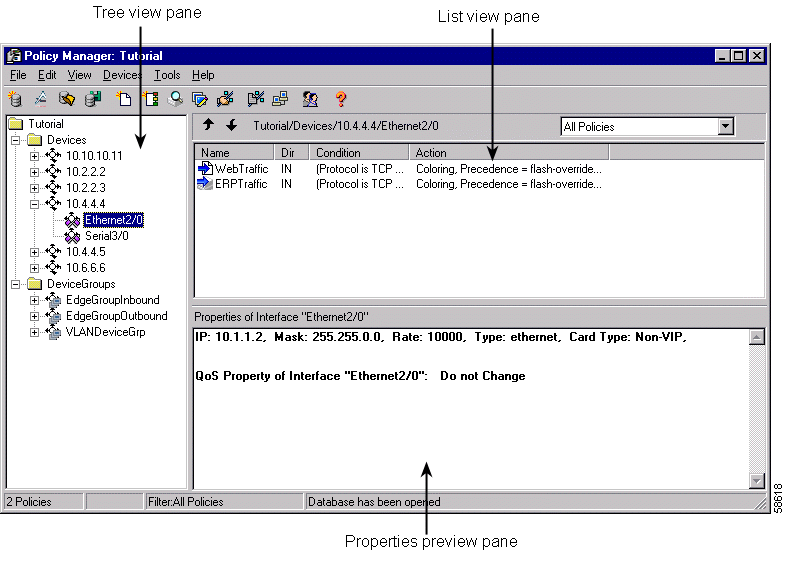
The tree view pane (Figure 3-2) shows the devices and device groups being managed in QPM. The Devices directory contains a separate folder for each device. Most device folders contain a list of interfaces on which you define QoS policies. For some devices, you define policies directly on the device folder.
The Device Groups directory contains the device groups you have defined. Device groups are groups of interfaces that you intend to manage using identical policies. You must treat all interfaces in a device group identically.
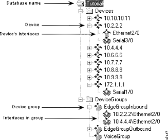
The tree view pane is where you start when creating a policy. If the device is not yet defined in the QoS database, you must first define it and add its interfaces. You must select the device or interface on which you want to define a policy in the tree view before you can create (or change) the policy.
| Icon | Description |
|---|---|
| Device |
| Device group |
| Interface |
| Interface on which the QoS property has been changed or policies have been defined. |
The list view pane (Figure 3-3) shows the policies that are defined on the interface, device, or device group selected in the tree view.
If you select an interface that belongs to a device group, the list of policies includes those defined on the device group, as well as those defined directly on the interface. You cannot edit or change the order of group policies when viewing them from a member interface. Group policies are always given lower priority than individual interface policies.
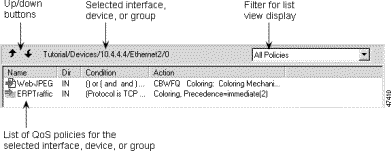
The top bar of the list view includes the following items:
Each policy in the list is preceded by an icon that indicates the direction of the policy (inbound or outbound) and its status (enabled or disabled). Table 3-2 describes these icons.
| Icon | Description |
|---|---|
| Inbound policy |
| Outbound policy |
| Inbound policy on device group |
| Outbound policy on device group |
| Disabled policy |
The properties preview pane displays the properties of the device, device group, interface, or policy selected in the tree or list view panes. This can help you determine if you have defined the properties and filter conditions correctly. You can choose not to display the properties preview pane by selecting View>Properties Preview. Repeat this action to redisplay the pane.
You can use the standard Windows cut, copy, and paste functions to manipulate policies in the QPM list view pane.
Step 1 Select the policy you want to cut or copy, or the folder in the tree view in which you want to paste the policy.
Step 2 Use these commands from the Edit menu or from the right mouse button popup menu to cut, copy, or paste.
You can change the main Policy Manager window to display information according to your preferences. Table 3-3 lists the available commands for changing the main Policy Manager window.
| If you want to... | Command | Description |
|---|---|---|
Display or hide the tool bar | View>Tool Bar | The tool bar is the row of short-cut buttons beneath the menu. When Tool Bar is checked on the View menu, the tool bar is displayed. |
Display or hide the status bar | View>Status Bar | The status bar is at the bottom of the window, and displays informative messages as you use Policy Manager. When Status Bar is checked on the View menu, the status bar is displayed. |
Display or hide the properties preview pane | View>Properties Preview | The properties preview is displayed in the lower right pane of the window, and shows the properties of the selected device, interface or policy statement. When Properties Preview is checked on the View menu, the properties preview is displayed. |
You must periodically save your changes to the QoS database. However, saving your changes to the database does not apply those changes to the network devices. You must use Distribution Manager to deploy your new or changed policies to the devices.
Step 1  Click the Save button, or select File>Save.
If the QoS Manager service is not available when you try to save the database, the database is saved to your local disk. Check the machine that is running QoS Manager to ensure it is running properly and try saving the database again.
From the Policy Manager interface, you can close Policy Manager only, or close both Policy Manager and Distribution Manager.
Step 1 To close Policy Manager without closing Distribution Manager, select File>Close.
To close both Policy Manager and Distribution Manager, select File>Exit.
Distribution Manager enables you to deploy policies to network devices. The following topics provide you with the basics for using Distribution Manager:
 |
Note When working with QPM Distribution Manager, you can click the Help button in any of the dialog boxes to access context-sensitive online help. |
Start Distribution Manager to distribute policies and QoS settings to network devices.
Step 1  Click the Distribution Manager button on the Policy Manager tool bar or select Tools>Distribution Manager in Policy Manager.
Distribution Manager starts.
The main Distribution Manager window (Figure 3-4) is divided into three panes.
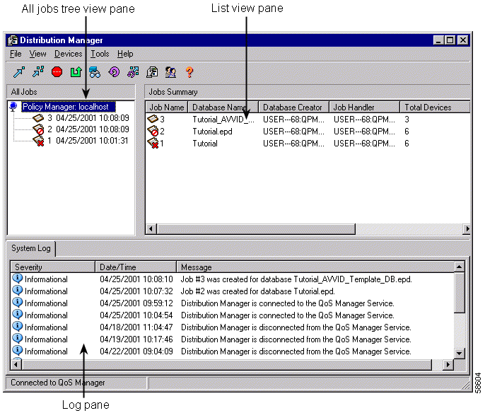
The All Jobs Tree View pane (Figure 3-5) shows all the jobs that you have created from QoS databases. Each job is assigned a number, which is the name of the job.
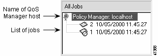
The root of the tree shows the name of the machine that is running the QoS Manager service to which Distribution Manager is connected: localhost means that QoS Manager resides on the same machine as Distribution Manager.
When you select a job in the list, the contents of the job are displayed in the right-hand list view pane. When no job is selected, or when you select the root of the tree, the right-hand list view shows the details for all the jobs listed in the tree.
| Icon | Description |
|---|---|
| QoS Manager host |
| Job |
| Canceled job |
The list view pane shows the contents of the job selected in the All Jobs Tree View (Figure 3-6). If no job is selected in the tree, the list shows the details for all jobs listed in the tree (Figure 3-7).

Job summaries have the following details:

Job contents have the following details:
The log pane (Figure 3-8) displays logs of event messages.
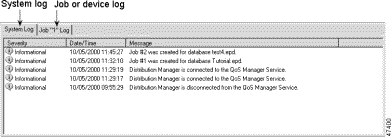
The pane has two tabs to display three types of logs:
You can change the main Distribution Manager window to display information according to your preferences. Table 3-5 lists the available commands for changing the main Distribution Manager window.
| If you want to... | Command | Description |
|---|---|---|
Display or hide the tool bar | View>Toolbar | The tool bar is the row of short-cut buttons beneath the menu. When Toolbar is checked on the View menu, the tool bar is displayed. |
Display or hide the log pane | View>Log | The log pane is the bottom half of the main window, and displays log messages for the system, selected job, or selected device. When Log is checked on the View menu, the log pane is displayed. |
Display or hide the status bar | View>Status Bar | The status bar is at the bottom of the window, and displays informative messages as you use Distribution Manager. When Status Bar is checked on the View menu, the status bar is displayed. |
If Policy Manager is not running, you can start it from Distribution Manager.
Step 1  Click the Policy Manager button, or select Tools>Policy Manager.
The Policy Manager application starts.
From the Distribution Manager interface, you can close Distribution Manager only, or close both Distribution Manager and Policy Manager.
Check the Status column to make sure that all distribution activities are complete or have been stopped.
Step 1 To close Distribution Manager without closing Policy Manager, select File>Close.
To close both Distribution Manager and Policy Manager, select File>Exit.
This tutorial is based on an example enterprise network that consists of a campus site and several remote sites. Each tutorial lesson applies QPM techniques and principles to specific segments of this network. In each lesson, a diagram clearly illustrates the relevant network segments, the data path, and the QoS features or policies applied.
 |
Note This example enterprise network does not include the segments that are relevant for configuring QoS for Voice over IP (VoIP). A separate QoS database is provided for configuring QoS for VoIP. A full description of this type of configuration is provided in Lesson 8Providing End-to-End QoS for VoIP over the Enterprise WAN. |
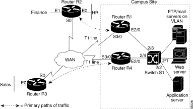
The campus site contains the following components:
This remote site contains a Cisco 2500 router (referred to as router R2), running IOS version 12.0. In the scenario for this tutorial, this router connects the organization's Finance and HR users to the WAN. These users primarily require data from the application server and the FTP/Web server on the campus site. The primary path of data from these servers is from router R1 on the campus site to the remote router R2.
This remote site contains a Cisco2500 router (referred to as router R3), running IOS version 12.0. This router connects the organization's Sales users to the WAN. These users primarily communicate with the application and web servers on the campus site. The primary path of data from these servers to the Sales users is through router R4 on the campus site to the remote router R3.
In this lesson you will learn how to create a QoS database comprising the devices and their interfaces that will be used in Lessons 2-6 of this Tutorial. The devices you will use to create the database are based on the example enterprise network illustrated in Figure 3-9.
When creating a QoS database, you can:
If you want to create policies and deploy them using actual devices that exist in your network, you need to obtain the IP addresses of the appropriate devices. Otherwise, you can use the example IP addresses in this tutorial so that you can follow the lessons without affecting your network. See Sample Network Device Information.
In this lesson you will learn the following:
Table 3-6 lists the technical details of the devices in the Tutorial example network that you need to know in order to create a QoS database and to follow lessons 2-6. Not all interfaces on the devices are listed.
| Lesson Number | Device Name | Device Model and IP Address | Software Version | Interfaces | IP Address | Mask |
|---|---|---|---|---|---|---|
3,5 | R1 | 7200 | 12.0 | Ethernet2/0 Standard Ethernet 10,000 Kbit/sec (10 Mb/sec) | 10.1.1.1 | 255.255.0.0 |
Serial3/0 T1 line at 1544 Kbit/second (propPointToPointSerial) | 10.2.2.2 | 255.255.0.0 | ||||
| R2 | 2500 | 12.0 | Ethernet0 Standard Ethernet 10,000 Kbit/sec (10 Mb/sec) | 10.10.10.1 | 255.255.255.0 |
Ethernet1 Standard Ethernet 10,000 Kbit/sec (10 Mb/sec) | 10.10.11.1 | 255.255.255.0 | ||||
Serial0 T1 line at 1544 Kbit/second (propPointToPointSerial) | 10.2.2.3 | 255.255.0.0 | ||||
| R3 | 2500 | 12.0 | Ethernet0 Standard Ethernet 10,000 Kbit/sec (10 Mb/sec) | 10.10.12.1 | 255.255.255.0 |
Serial0 T1 line at 1544 Kbit/second (propPointToPointSerial) | 10.4.4.5 | 255.255.0.0 | ||||
2,3,5,6 | R4 | 7200 | 12.0 | Ethernet2/0 Standard Ethernet 10,000 Kbit/sec (10 Mb/sec) | 10.1.1.2 | 255.255.0.0 |
Serial3/0 T1 line at 1544 Kbit/sec (propPointToPointSerial) | 10.4.4.4 | 255.255.0.0 | ||||
4 | S1 | 6509 | 5.5 | VLAN20 propVirtual | 10.10.1.2 | 255.255.0.0 |
Other interface and device addresses might be used in the lessons.
This topic describes how to add a device (router or switch) to the database. The procedure in this example describes how to add router R4 from the network configuration example. The procedure is identical for adding any other router or switch, except for the device details. Refer to Table 3-6 for the technical details of all the devices in the network configuration example. It is recommended that you perform the following procedure for all the devices in this network configuration example.
The topic assumes that you are starting with an empty database.
Step 1 Open the New Device dialog box by selecting Devices>Device>New in the Policy Manager.
Step 2 Enter device information in the New Device dialog box.
a. At minimum, you must supply the following information:
In this example, router R4 is 10.4.4.4, the community string is public, and both passwords are test (Figure 3-10).
b. If your device is offline (for example, if you are using the IP addresses used in this lesson instead of addresses for devices on your network), you must select the device model and the software version in the relevant fields. In this example, router R4 is a Cisco 7200 running IOS software version 12.0.
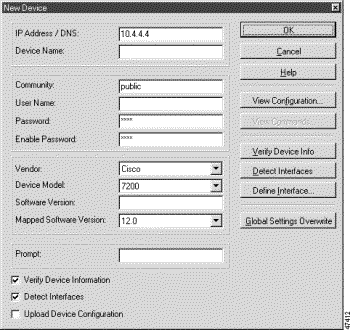
Step 3 Select/deselect the check boxes.
a. If the device is online and you want to add its interfaces automatically:
b. If you want to add the interfaces manually to an offline or online device:
Step 4 Click OK.
QPM creates a folder for the device (in this example, router R4) in the tree view using the IP address of the device.
This topic describes how to add router interfaces and switch ports and VLANs to the database. Router R4 is used as an example. The procedure differs depending on whether or not the device is online.
 |
Note If you are using devices that exist online in your network, you can automatically detect their interfaces. In this tutorial, the devices and their interfaces listed in Table 3-6 3-21 are offline, enabling you to manually add them to the database without affecting your network. |
When you add a switch's ports to the database, the available interfaces will include the ports and any VLANs that are configured on the switch. A VLAN includes several of the switch's ports. In order to deploy a policy defined on a VLAN to all its associated ports, you must add each port to the database and define the QoS style as VLAN-based (as opposed to port-based). See Defining the QoS Style for a Switch's Ports, for further information.
This topic assumes that you have added the device (online or offline) to the database. If you are working online, continue with Adding the Interfaces if the Device Is Online. If you are working offline, continue with Adding the Interfaces if the Device Is Offline.
This section describes how you can automatically detect the interfaces for a device that is online in your network, once the device has been added to the database.
Step 1 Detect the available interfaces:
a. Ensure that the Verify Device Information and Detect Interfaces check boxes are selected (by right-clicking the device in the tree view and selecting Device Properties).
QPM queries the device, fills in the Device Model and Software Version fields, and obtains a list of the device's interfaces.
 |
Note If the software version running on the device is not supported, QPM maps to the most similar supported version. This feature is described in Lesson 5Updating the Database After Software Upgrades. |
QPM opens the Detect Interfaces dialog box when it has a complete list of interfaces.
Step 2 Select the interfaces you want to manage:
a. In the Detect Interfaces dialog box, ensure that the interfaces you want to manage are in the selected interfaces list, and move any you do not want to manage to the available interfaces list.
b. Click OK when finished.
The device's interfaces are included as members of the device folder in the tree view (see Figure 3-12).
 |
Note If you want to apply QoS on a switch's VLAN (as is the case for switch S1), make sure that the VLAN and all of its ports are in the selected interfaces list. |
If the device is offline, you need to add the interfaces manually. This section describes how to manually add the interfaces for router R4, once it has been added to the database. The procedure for adding the interfaces for any other device is similar, except for the device details. Refer to Table 3-6 for the interface details of all the devices in the network configuration example. It is recommended that you perform the following procedure for all the devices in the network configuration example.
Step 1 Add a new interface:
a. Ensure that the Verify Device Information and Detect Interfaces check boxes are deselected (by right-clicking the device in the tree view and selecting Device Properties), so that QPM does not try to query the device.
b. Right-click the device in the tree view and select New Interface.
QPM opens the New Interface dialog box.
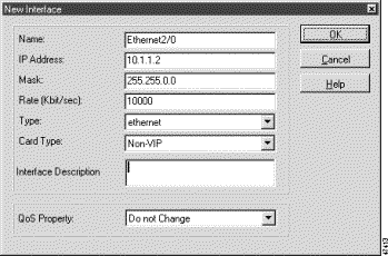
c. Enter the details for the Ethernet2/0 interface in the appropriate fields. You can obtain all of the relevant information for this dialog box from Table 3-6. You do not need to select the QoS Property value at this stage—this will be defined specifically for the device in a later lesson (see Configuring the QoS Property and Defining the QoS Style for a Switch's Ports).
Figure 3-11 shows the completed New Interface dialog box.
d. Click OK in the New Interface dialog box.
e. Repeat this procedure for the Serial3/0 interface (see Table 3-6 for the interface's details).
f. Click OK in the New Device dialog box to return to the tree view.
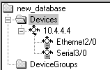
Figure 3-12 shows the tree view that now includes router R4 with its interfaces.
Now, repeat the above procedure in order to add the other devices in the network example to the database.
 |
Note If you are adding the interfaces for switch S1, assume that VLAN20 includes three interfaces (Ethernet2/0, Ethernet2/1 and Ethernet2/2), and define these interfaces in the database, following the procedure above. Choose fictitious IP addresses for these interfaces. |
This topic explains how you can add multiple devices at one time to the QoS database. Instead of adding each device individually, you can import a list of devices from a device inventory that was created using CiscoWorks2000 Resource Manager Essentials. If you have many devices to import, consider creating separate databases, each containing a different set of devices.
It is assumed that you have previously exported a device inventory using CiscoWorks2000 Resource Manager Essentials.
Step 1 From the Policy Manager, select Devices >Import.
QPM opens the Select RME File dialog box.
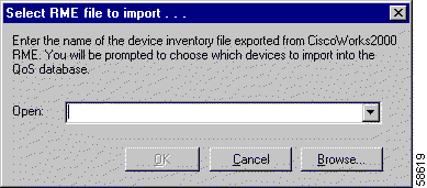
Step 2 Enter the full path and name of the inventory file, or click Browse and select it. Click OK when the correct file is entered.
QPM opens the Import Devices dialog box for the selected inventory file, and begins querying the devices in the inventory, adding them to the Known Devices list. The query can take a long time if there are many devices. If a device cannot be queried, either because it is unavailable, or the SNMP query failed, this is indicated, and you will not be able to import the device.
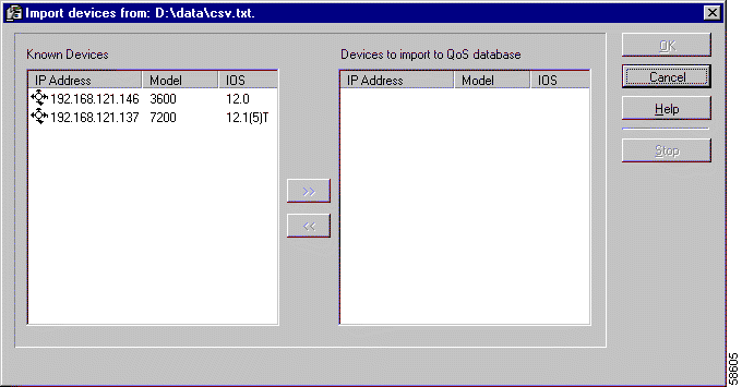
While QPM is querying the devices, you can click Stop to make QPM stop the query. If you stop the query, QPM only lets you select from the devices already queried.
 |
Note You can make other changes in Policy Manager while QPM queries the devices. When QPM is finished with the query, you are returned to the Import Devices dialog box to continue the import process. |
When QPM has finished querying the devices, a system message appears, informing you that the device inventory has been processed, and that you should choose the devices to be imported into the Qos database.
Step 3 Select the devices you want to add to the QoS database in the Known Devices list and click >> to add them to the import list. You can select multiple devices using Ctrl+click or a range of devices using Shift+click.
If QPM could not query a device, do not add the device to the database until you can determine why the query failed. Common causes of query failure include incorrect Telnet or SNMP passwords, incorrect IP addresses, and unavailable devices.
When you are satisfied with the list of devices to import, click OK.
Step 4 QPM asks if you want to detect interfaces on the devices. The interface detection process might take several minutes depending on the number of devices, interfaces, and speed of the network connection.
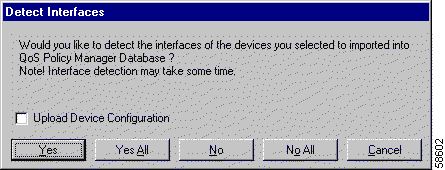
Select one of the following:
 |
Note You can also upload the device configuration at this time by checking the Upload Device Configuration check box. See Uploading Existing Device Configurations for more information. |
When QPM has finished detecting interfaces, QPM adds the devices and their interfaces to the tree view and closes the Import Devices dialog box.
QPM enables you to upload existing QoS configurations on devices. This feature is useful if you have already configured QoS properties and policies on devices, using the CLI. Instead of redefining the QoS characteristics, you can use the upload feature to automatically update the QPM database with the QoS information when you add the device.
You can only upload a QoS configuration for a device that is online. For this lesson, use any online device in your network that has a QoS configuration (but hasn't yet been imported) and add it to the database. See Adding a Device to the QoS Database.
You can upload existing device configurations:
 |
Note You can upload a device configuration one time only. The Upload Device Configuration check box is disabled after you make QoS configuration changes to the device. |
This topic assumes that you have added the device and detected its interfaces, but have not yet configured its QoS properties.
Step 1 Right-click your online device in the tree view pane and select Device Properties.
QPM opens the Device Properties dialog box.
Step 2 Select the Upload Device Configuration check box and click OK.
The QoS configuration that is running on the device is translated to QoS properties and policies and is added to the policy database.
Step 3 After the upload is completed, you will be prompted to view an HTML report generated by QPM in your system browser. Click Yes if you want to view the upload report.
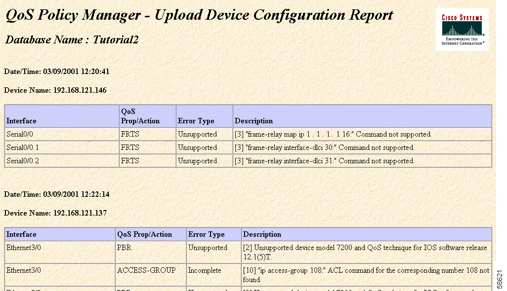
This report logs all the QoS configurations that were not successfully uploaded to the database. Upload failure may be caused by incomplete configurations that exist on the router, or unsupported options.
The report displays the following information for the device:
See Device Upload Error Messages, for a complete list of error messages that you may see in an Upload Device Configuration Report.
In this lesson, you will learn how to create and deploy a simple policy on a router. As an example, this lesson uses router R4, that you added to the QoS database in the previous lesson (Adding a Device to the QoS Database). The policy in this example sets the IP precedence for web traffic that goes through router R4. See Understanding the Tutorial Example Network, for a description of the example network used in this tutorial. The purpose of this policy is to color the web traffic for the Sales group, because the web server behind R4 hosts a significant application used by Sales, and Sales requires good response from this server.
In order to make a meaningful policy, you must not only color the traffic on the inbound interface to the router (interface Ethernet2/0, which connects the web server to R4), but you must choose a QoS property for the outbound interface Serial3/0 (Figure 3-17). You will implement weighted fair queuing (WFQ). This ensures that the colored traffic receives the appropriate percentage of overall bandwidth.

In this lesson you will learn the following:
This lesson assumes you have already added router R4 to the QoS database.
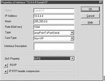
This topic describes how to configure the QoS property on the interfaces to determine which queueing method will be used. You will configure the QoS property on the Serial3/0 interface so that it uses weighted fair queuing (WFQ). You do not need to change the QoS property of the Ethernet2/0 interface because you are only creating a policy for inbound traffic on Ethernet2/0.
Step 1 Right-click Router R4's Serial3/0 interface in the tree view (Figure 3-12) and select Interface Properties.
QPM opens the Properties of Interface dialog box.
Step 2 Select WFQ in the QoS Property field (Figure 3-18).
Step 3 Click OK.
This topic describes how to create a policy to color traffic on an inbound interface. The purpose of this policy is to give high priority to web traffic passing through router R4's Ethernet2/0 inbound interface.
Step 1 Create the policy.
a. Select Router R4's Ethernet2/0 interface in the tree view.
b.  Click the New QoS Policy button, or select File>New>Policy.
QPM opens the Properties of Policy dialog box, in which you will create the policy.
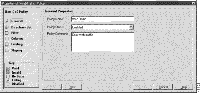
c. In the General Properties page, change the name of the policy and add a meaningful comment. For this policy, use "WebTraffic" and "Color web traffic." Figure 3-19 shows the completed general properties page.
d. Click Next to open the Direction Properties page.
Select the In direction to indicate that the policy is for inbound traffic.
Step 2 Define the policy's filter.
a. Click Next to open the Filter Properties page.
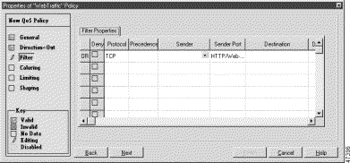
b. In the filters list, select the following values in the same row:
These are the only conditions required to identify web traffic. Figure 3-20 shows the completed Filter Properties dialog box.
Step 3 Define the policy's coloring action.
a. Click Next to open the Coloring page.
b. Select the Coloring Properties check box. The fields for the coloring properties become active.
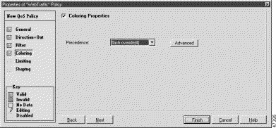
c. Select flash-override (4) in the Precedence field to give a higher priority to the traffic that satisfies the policy's filter. Figure 3-21 shows the completed Coloring Properties dialog box.
d. Click Finish to save the policy.
QPM adds the policy to the Serial3/0 folder.
Step 4  Save your definitions and policies to the database.
a. Click the Save button, or select File>Save, to save your policy changes.
Because this is the first time you have saved the database, QPM opens the Save Database dialog box and you are prompted to name it.
b. For this example, type Tutorial in the Database Name field.
c. Enter a description of the database in the Database Description field, for example, enter Sample tutorial network.
d. Click OK to save the database.
After you have saved your policies in the QoS database, they must be deployed to the devices in the network where they will be implemented.
 |
Note If you are working with the examples provided in the tutorial and the device is not in your network, you will not be able to deploy your policies. |
Step 1  In the Policy Manager, click the Distribution Manager button, or select Tools>Distribution Manager, to start Distribution Manager.
Step 2 In Distribution Manager, select Devices>Create Job to create a distribution job from the Tutorial database.
QPM opens the Create Job dialog box.
Step 3 Select the Tutorial database and click OK.
QPM creates a distribution job based on the policy definitions in the selected database. The job consists of the commands required to reconfigure the devices to implement your policies. Only the changes made since you last distributed the database are included in the job.
Step 4 Select the job you just created in the tree view.
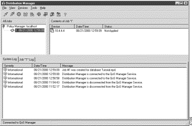
When you select the job, QPM displays the contents of the job in the list view. The list view shows the devices whose configurations will be changed by the job. If you double-click the device name in the list view, QPM displays the commands that will be sent to the device when you apply the job (the device must be available on the network).
Figure 3-22 shows the job selected in the Distribution Manager window.
Step 5  Click the Apply Job button, or select Devices>Apply.
QPM starts applying the changes defined in the job to the network devices. You can view the job results in the logs displayed in the Log pane at the bottom of the window.
In this lesson, you will learn how to treat a set of device interfaces as a group, and create and deploy a simple coloring policy across the members of that group. The policy in this example will set the IP precedence for Enterprise Resource Planning (ERP) traffic that goes through routers R1 and R4 (see Figure 3-9 for the overall network diagram).
In this lesson you will learn the following:
If you want to create a policy and deploy it on a device that exists in your network, obtain the IP address of an appropriate device. Otherwise, you can use the IP addresses in this lesson so that you can follow these steps without affecting your network.
This lesson assumes that you have added routers R1 and R4 to the QoS database, as described in Lesson 1—Adding a Device to the QoS Database.
Device groups allow you to treat selected interfaces or subinterfaces as a single unit, so that you can easily apply common policies or QoS settings to the group.
This topic describes how to create two device groups, one combining the inbound interfaces of routers R1 and R4, and the other combining the outbound interfaces of the routers.
Step 1 Create a device group for the Serial3/0 interfaces on routers R1 and R4, and set the QoS property for the device group to WFQ.
a. In the Policy Manager, select Devices>Device Group>New, or select the DeviceGroups folder in the tree view, right-click, and select New Device Group.
QPM opens the Device Group dialog box.
b. In the Device Group dialog box, enter the following information:
c. Click Add/Remove in the Group Members area.
QPM opens the Add/Remove Group Members dialog box.
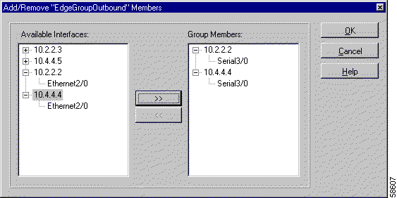
d. In the Add/Remove Group Members dialog box, open the trees for routers R1 (10.2.2.2) and R4 (10.4.4.4), select the Serial3/0 interfaces for each device in turn and click >> to add each interface to the group (Figure 3-23).
e. Click OK when finished.
Figure 3-24 shows the Device Group dialog box after you have added the Serial3/0 interfaces as group members.
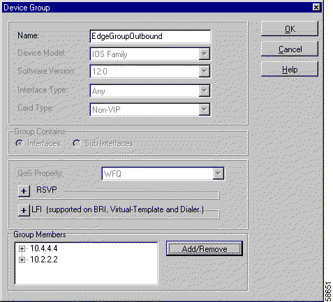
f. Click OK in the Device Group dialog box.
QPM asks you to confirm that you want the group properties to override the properties already defined on R4's Serial3/0 interface (properties created in Lesson 1—Adding a Device to the QoS Database). Click Yes.
QPM creates the group and adds it to the DeviceGroups folder in the tree view.
Step 2 Create a device group for the Ethernet2/0 interfaces on routers R1 and R4.
a. In the Policy Manager, select Devices>Device Group>New, or select the DeviceGroups folder in the tree view, right-click, and select New Device Group.
QPM opens the Device Group dialog box.
b. In the Device Group dialog box, enter the following information:
c. Click Add/Remove in the Group Members group.
QPM opens the Add/Remove Group Members dialog box.
d. In the Add/Remove Group Members dialog box, open the trees for routers R1 (10.2.2.2) and R4 (10.4.4.4), select the Ethernet2/0 interfaces for each device in turn and click >> to add each interface to the group.
e. Click OK when finished.
QPM adds the interfaces to the Group Members list in the Device Group dialog box.
f. Click OK in the Device Group dialog box.
Figure 3-25 shows the tree view with the completed device group entries.
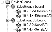
A policy that is created on a device group is applied to all the interfaces belonging to the group. This avoids the need to create individual policies for each interface.
In this lesson, you will create a policy on the EdgeGroupInbound group to color ERP traffic.
Step 1 Create the policy.
a. Select the EdgeGroupInbound group in the tree pane.
b.  Click the New QoS Policy button, or select File>New>Policy.
QPM opens the Properties of Policy dialog box.
c. In the General Properties page, change the name of the policy and add a meaningful comment. For this policy, use "ERPTraffic" and "Color ERP traffic for the HR, Finance, and Sales organizations."
d. Click Next to open the Direction Properties page.
Select the In direction to indicate that the policy is for inbound traffic.
Step 2 Define the policy's filter.
a. Click Next to open the Filter Properties page.
Because the ERP server in this example is dedicated to the ERP applications, as is typically the case, you color all traffic from the server. If other applications were on the same server as the ERP application, you would also use a port filter.
b. Select the following values in the same row:
Step 3 Define the policy's coloring action.
a. Click Next to open the Coloring page.
b. Select the Coloring Properties check box. The fields for the coloring properties become active.
c. Select flash-override (4) in the Precedence field to give a higher priority to the traffic that satisfies the policy's filter.
d. Click Finish to save the policy.
QPM adds the policy to the EdgeGroupInbound folder.
Step 4  Click the Save button, or select File>Save, to save the policy in the database. Because you used a host name for the ERP server, QPM asks if you would like the host name resolved to its IP address. Policies can be distributed to the device only if the host names are converted to IP addresses. Click Yes to have QPM resolve the host name. (Click No if you are following along in this lesson without using actual host names that exist in your network.)
Step 5 Distribute the policy to the network, following the procedure described in Distributing Policies to the Network.
In this lesson, you will learn how to limit the bandwidth that is available to a specific application. The policy in this example will limit FTP traffic passing through switch S1 to a specified bandwidth (see Figure 3-9 for the overall network diagram). FTP traffic that exceeds this bandwidth will be discarded. The purpose of this policy is to prevent FTP traffic from flooding the network and thus reducing the performance of the more important applications on the network.
You will define an application service alias for FTP traffic from the central site, and use the alias to set the limit for FTP traffic to 1024 Kbps (Figure 3-26).
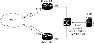
In order to create and deploy the policy in this lesson, you must have a switch configured with a VLAN in your network. If you have one, use its IP address for the example.
Otherwise, you can use the example IP addresses and values provided in this lesson, so that you can follow the steps without affecting your network.
Since you will be defining a limiting policy on the S1 switch, you first need to add the switch and its interfaces to the database. This lesson assumes that you have already added Switch S1 and its interfaces to the QoS database (see Lesson 1—Adding a Device to the QoS Database), but that you still need to define the QoS style for the switch's ports. This lesson also assumes that you have completed all the steps in the previous lessons.
In this lesson you will learn the following:
Switch S1 is a Catalyst 6000 switch running CatOS version 5.5. In this example, a VLAN has been configured on switch S1. The VLAN includes several of the switch's ports. The limiting policy will be defined on this VLAN, therefore, you do not have to define the policy on each port individually. However, in order to ensure that the policy is applied to all the ports that belong to the VLAN, you must add each port to the database and define the QoS style as VLAN-based (as opposed to port-based).
It is recommended that you create a device group of the switch's ports that are included in the VLAN and define the QoS style on the device group itself. This saves you having to define the QoS style on each port separately.
The following procedure describes how to create a device group for the VLAN's ports and define their QoS style as VLAN-based.
This topic assumes that each of the switch's ports have been added to the database (see Adding a Device's Interfaces).
Step 1 Create a device group for the three ports (Ethernet2/0, Ethernet2/1 and Ethernet2/2) in VLAN20 on switch S1.
a. In the Policy Manager, select Devices>Device Group>New, or select the DeviceGroups folder in the tree view, right-click, and select New Device Group.
QPM opens the Device Group dialog box.
b. In the Device Group dialog box, enter the following information:
c. In the Group Members area, select Ports from the drop-down list, so that only ports (not VLANs) are displayed in the list of available group members.
d. Click Add/Remove in the Group Members area.
QPM opens the Add/Remove Group Members dialog box.
e. In the Add/Remove Group Members dialog box, open the tree for the device, select the Ethernet ports for the device in turn and click >> to add each port to the group (Figure 3-27).
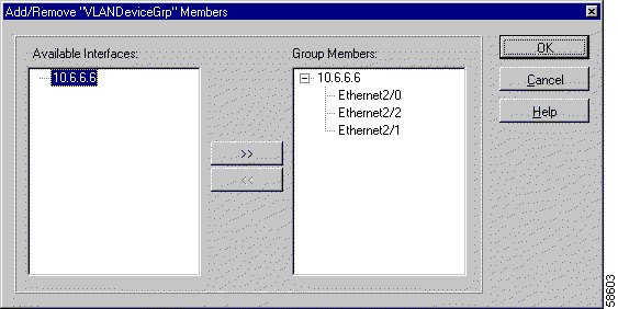
f. Click OK when finished.
Figure 3-28 shows the Device Group dialog box after you have added the Ethernet ports as group members.
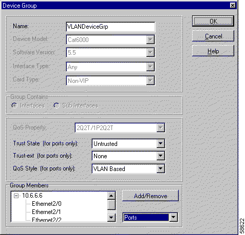
Step 2 Select VLAN Based in the QoS Style field (Figure 3-28) to determine that QoS configurations will apply to the VLAN and not to the individual ports.
Step 3 Click OK in the Device Group dialog box.
QPM creates the device group with a VLAN-based QoS style and adds it to the DeviceGroups folder in the tree view.
An application service alias can be defined when you want to identify a particular type of network traffic source from a host or subnet. You can use application service aliases to simplify the writing of your policies, because you can write a policy for the application service instead of one for each host.
In this example, you will create an application service alias for FTP traffic. The filter in your limiting policy will be based on this application alias.
Step 1 Create an application service alias for FTP traffic.
a.  In the Policy Manager, click the Application Services button, or select Tools>Application Services.
QPM opens the Application Services dialog box.
b. Click Add to open the Application Service dialog box.
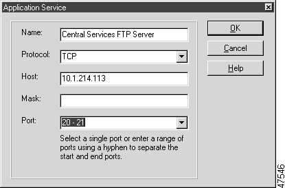
c. In the Application Service dialog box, fill in the required information to identify the source of the FTP traffic, and to give the application service alias a name.
In this example, you will identify the FTP traffic by using the following attributes (Figure 3-29):
Click OK when finished to return to the Application Services dialog box.
d. Click OK in the Application Services dialog box.
This topic shows how to create a policy on VLAN20 on switch S1 to limit the bandwidth available to FTP traffic.
Step 1 Create the policy.
a. Select VLAN20 in the tree view.
b.  Click the New QoS Policy button, or select File>New>Policy, or right-click in the policy list view and select New QoS Policy.
QPM opens the Properties of Policy dialog box.
c. In the General Properties page, change the name of the policy and add a meaningful comment. For this policy, use "FTP Traffic" and "Limit bandwidth for FTP traffic".
d. Click Next to open the Direction Properties page.
e. Select the In direction to indicate that the policy is for inbound traffic.
Step 2 Define the policy's filter. The aim is to identify all FTP traffic coming from the Central Services FTP Server.
a. Click Next to open the Filter Properties page.
b. In the filters list, click in the Sender field and select the type of sender, as follows:
c. Click OK.
Step 3 Define the policy's limiting action, which limits the bandwidth available to the specified application.
a. Click on Limiting on the left side of the Properties of Policy dialog box to open the Limiting Properties page, or click Next until you reach this page.
b. Select the Limiting Properties check box.
The limiting properties fields are enabled.
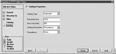
c. Define the following limiting properties to specify a maximum rate for the traffic and to remove IP precedence from traffic that exceeds this rate:
Figure 3-30 shows the Limiting Properties page after you have defined all the properties.
d. Click Finish to save the policy.
Step 4  Click the Save button, or select File>Save, to save the policy in the database.
QPM enables you to verify whether the configuration of the devices in your network is different to what was defined for the devices in your QPM database. You can use this feature to check if any changes have been made to any of your network devices.
After this validation process, you can distribute policies to the network as usual.
Step 1 Create a job in Distribution Manager.
a.  Click the Distribution Manager button, or select Tools>Distribution Manager, to start Distribution Manager.
b. In Distribution Manager, select Devices>Create Job to create a distribution job from the Tutorial database. QPM opens the Create Job dialog box.
c. Select the Tutorial database and click OK. QPM creates a distribution job based on the policy definitions in the selected database. The job consists of the commands required to reconfigure the devices to implement your policies. Only the changes made since you last distributed the database are included in the job.
Step 2 Check the device configuration.
a. Select the job you just created in the tree view.
When you select the job, QPM displays the contents of the job in the list view, which shows the devices whose configurations will be changed by the job. If you double-click the device name in the list view, QPM displays the commands that will be sent to the device when you apply the job (the device must be available on the network).
b.  Click the Verify Device Configuration button, or select Devices>Verify Device Configuration.
QPM starts checking the configuration of the devices in the job. The result of this validation process appears in the Status column and can be either Matched or Mismatched. Details can be viewed in the log in the lower section of the Distribution Manager window.
Step 3 Apply the job.
a.  Click the Apply button, or select Devices>Apply. QPM starts applying the changes defined in the job to the network devices. You can view the results of the jobs in the logs displayed in the bottom pane of Distribution Manager.
In this lesson, you will learn how to update the QoS database to recognize that you have upgraded the software on a device.
QPM uses the device IOS version number to load device capabilities to the database. All sub-versions of a certain version are mapped to the major version, unless QPM explicitly supports the minor version. New minor versions are mapped to the last supported minor version. For example, version 12.2(1)T would be mapped to version 12.2, and version 12.2(4)T would be mapped to version 12.2(2)T. QPM provides you with the option of manually changing the mapped version number if you require the QoS features of a different version.
In most cases, your QoS configuration and policies remain unchanged after a software upgrade. However, in certain cases, QPM changes the implementation of policies to take advantage of the features of a new software release (without changing the meaning of your policies). Table 3-7 explains the changes that are made for some software upgrades.
| IOS Software Upgrade | Policy Conversion |
|---|---|
11.1cc to 11.2 or 11.3 | Converts coloring policies from CAR to policy based routing (PBR). |
11.2 or 11.3 to 12.0 | Converts coloring policies from PBR to CAR. |
12.0 to 12.1 on a 2500 router | Converts coloring policies from PBR to CAR. |
Upgrading the device software does not affect any device groups to which the device's interfaces belong. You must recreate the device groups if you want them to be restricted to the updated software version.
In this lesson, you will learn the following:
This lesson assumes that you have completed the steps in the previous lessons.
For the purpose of this lesson, assume that you have upgraded the IOS software version on routers R1 and R4 from version 12.0 to version 12.1(6)E.
Step 1 Start QPM and open the Tutorial database.
Step 2 Change the device properties for router R1:
a. Select router R1 (10.2.2.2) and select Devices>Device>Properties.
QPM opens the Device Properties dialog box.
b. Click the Verify Device Info button.
QPM queries the router and updates the software version number and device model, and makes policy conversions if required.
(If you are not using a real device, instead of clicking Verify Device Info, select 12.1(6)E in the Mapped Software Version field.)
 |
Note The detected software version is displayed in the Software Version field. If this version is not supported, QPM maps to the most recent, most similar supported version, which is displayed in the Mapped Software Version field. You can manually select a different software version in this field if you require its specific capabilities. |
c. Click OK to save the changes to the device configuration. QPM informs you if there are any conflicts between the QoS configuration and policies defined on the device's interfaces and the new software version. You must resolve the conflicts before you can complete the changes to the device properties.
Step 3 Use the same procedure to change the software version for router R4 (10.4.4.4) to 12.1(6)E.
At this point, you have updated the software versions on the devices. However, this change has not affected the definitions of the EdgeGroupInbound and EdgeGroupOutbound device groups, even though these device groups contain only members from the R1 and R4 routers. To take advantage of IOS software version 12.1(6)E QoS features, you must recreate these device groups as IOS software version 12.1(6)E device groups.
To avoid having to recreate the existing policies in the device groups, you can copy them over to a new device group, then delete the old device group, and then rename the new device group.
Step 1 Create a new device group with software version 12.1(6)E:
a. Select Devices>Device Group>New to create a new device group.
QPM opens the Device Group dialog box.
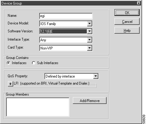
b. Enter a temporary name for the device group (egi) in the Name field, and select 12.1(6)E in the Software Version field (Figure 3-31).
c. Click OK when finished.
QPM creates the egi device group.
Step 2 Copy the ERPTraffic policy from the EdgeGroupInbound device group to the new device group:
a. Select the EdgeGroupInbound device group in the tree view pane.
b. Right-click on the ERPTraffic policy in the list view pane and select Copy. This copies the policy to the Windows clipboard.
c. Select the egi device group in the tree view pane.
d. Right-click in the list view pane, and select Paste. This pastes a copy of the ERPTraffic policy to the device group.
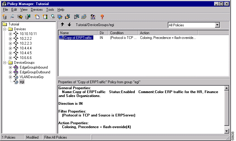
e. Double-click the Copy of ERPTraffic policy in the list view pane.
QPM opens the policy in the Properties of Policy dialog.
f. Change the name of the policy from "Copy of ERPTraffic" to "ERPTraffic" and click Finish.
QPM changes the name of the policy.
Step 3 Remove the devices from the EdgeGroupInbound device group and delete the device group.
a. Select the EdgeGroupInbound device group and select Devices>Device Group>Add/Remove Members.
QPM opens the Add/Remove Members dialog box.
b. Expand the tree for each group member and note which interfaces belong to the group.
c. Select each group member and click << to remove it from the group.
d. Click OK when finished.
Because there are policies defined on the group, QPM asks if you want the policies copied to the interfaces you are removing from the group. Click No All, because when you are finished, these policies will again be defined for the interfaces on a device group.
QPM removes the members from the group. EdgeGroupInbound should now have no members.
e. Select the EdgeGroupInbound device group and select Devices>Device Group>Delete.
QPM asks you to confirm that you want to delete the device group and the policies it contains. Click Yes. QPM deletes the device group.
Step 4 Add devices to the new egi device group and rename the device group.
a. Select the egi device group and select Devices>Device Group>Add/Remove Members.
QPM opens the Add/Remove Members dialog box.
b. Select the interfaces you removed from EdgeGroupInbound (10.2.2.2\Ethernet2/0 and 10.4.4.4\Ethernet2/0) and click >> to add them to the group.
c. Click OK when finished.
QPM adds the members to the group. The egi group should now have the same membership as the original EdgeGroupInbound device group.
d. Select the egi device group and select Devices>Device Group>Properties.
QPM opens the Device Group dialog box.
e. Change the name of the egi group to EdgeGroupInbound and click OK.
Step 5 Change the EdgeGroupOutbound device group to an IOS software version 12.1(6)E device group. Since there are no policies defined on this device group, you only need to remove the members from the device group, change the software version and then add the members back into the device group.
a. Select the EdgeGroupOutbound device group in the tree view pane and select Devices>Device Group>Add/Remove Members.
QPM opens the Add/Remove Members dialog box.
b. Expand the tree for each group member and note which interfaces belong to the group.
c. Select each group member and click << to remove it from the group.
d. Click OK when finished.
QPM informs you that it will change the QoS property for member interfaces to WFQ (because that is the QoS property defined for the group).
e. Click Yes.
f. Right-click on the EdgeGroupOutbound device group in the tree view pane and select Device Group Properties.
QPM opens the Device Group dialog box.
g. Select 12.1(6)E in the Software Version field and click OK.
h. Select Devices>Device Groups>Add\Remove Members.
QPM opens the Add/Remove Members dialog box.
i. Add the interfaces you removed from the device group (the Serial3/0 interfaces of routers R1 and R4) back into the group, by selecting each one and clicking >> to add it to the group.
j. Click OK when finished.
QPM informs you that the QoS property defined for the group will override the one defined on the interface, and asks you to confirm that you want to add the interface to the group.
k. Click Yes.
QPM adds the members to the group.
Step 6  Click the Save button, or select File>Save, to save your changes.
Step 7 Distribute your policy to the network, following the procedure described in Distributing Policies to the Network.
In this lesson you will learn how to create a multiple-action policy to police and color specific traffic generated from a network-based application, using Network Based Application Recognition (NBAR) to identify the application. Refer to Using Network Based Application Recognition (NBAR) with CBWFQ.
 |
Note IP CEF must be enabled on the device in order to use NBAR. At deployment, QPM checks if CEF is configured on the router for the relevant features. If not configured, QPM will issue a warning. See QoS Features That Require IP CEF or dCEF for more information. |
The policy in this lesson will apply the following actions to MIME type web traffic, specifically JPEG files, passing from a specific host through router R4 and out to the WAN (see Figure 3-9 for the overall network diagram):
QPM uses modular CLI to implement this policy. Modular CLI separates traffic into classes and defines properties for each class.
 |
Note The policy in this lesson can be created only if your IOS software version supports modular CLI and NBAR. |
In order to enable the options that will allow you to define the example policy, you will choose Class Based QoS in the QoS Property field for the outbound (Serial3/0) interface on router R4.
In this lesson you will learn the following:
This lesson assumes that you have completed the steps in the previous lessons.
If you are using actual devices in your network, make sure that the IOS version is 12.1(6)E or above.
If you want to create a policy and deploy it on a device that exists in your network, obtain the IP address of an appropriate device. Otherwise, you can use the IP addresses in this lesson so that you can follow these steps without affecting your network.
The first step in this lesson is to define the QoS property on Serial3/0 on router R4 as Class Based QoS. This will enable you to use NBAR properties as a filter during policy definition.
Before you can do this, you need to remove the outbound interface (Serial3/0 on router R4 from the device group to which it belongs (EdgeGroupOutbound), so that you can change its QoS property.
Step 1 Remove R4's S3/0 interface from the EdgeGroupOutbound device group.
a. Select the EdgeGroupOutbound device group in the tree view.
b. Select Devices>Device Group>Add/Remove Members or right-click on the EdgeGroupOutbound device group in the tree view and select Add/Remove Members.
QPM opens the Add/Remove Members dialog box.
c. In the Add/Remove Members dialog box, in the Group Members list, select router R4 (10.4.4.4) and click << to remove the device from the group (Figure 3-33). Click OK when finished.
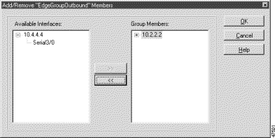
d. QPM warns you that the removed Serial3/0 interface will retain the QoS property defined for the group (WFQ) and requests confirmation of the removal. Click Yes.
The EdgeGroupOutbound device group now contains one device only (R1).
Step 2 Change the QoS property on the outbound interface (Serial3/0 on router R4) to Class Based QoS.
a. In the tree view, open the tree for router R4 (10.4.4.4).
b. Right click Serial3/0 and select Interface Properties.
QPM opens the Properties of Interface dialog box.
c. Select Class Based QoS in the QoS Property field.
d. Click OK.
QPM provides the capability to create multiple-action policies, if the IOS software version running on your device supports modular CLI. For this example, you will create a policy on the outbound interface (Serial3/0 on router R4) that performs three actions on the traffic that matches the filter (web traffic of MIME type from www.cisco.com):
Step 1 Create the policy.
a. Select router R4's Serial3/0 interface in the tree view.
b.  Click the New QoS Policy button, or select File>New>Policy or right-click in the policy list view and select New QoS Policy.
QPM opens the Properties of Policy dialog box, in which you will create the policy.
c. In the General Properties page, change the name of the policy and add a meaningful comment. For this policy, use "Multiple Action" and "Manage critical web traffic."
d. Click Next to open the Direction Properties page.
Select the Out direction to indicate that the policy is for outbound traffic.
Step 2 Define the policy's filter.
a. Click Next to open the Filter Properties page.
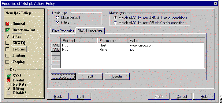
b. Click the NBAR Properties tab, since the traffic identification for this policy is via NBAR (Figure 3-34).
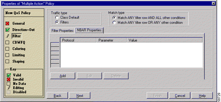
c. Click Add.
The NBAR Properties dialog box is displayed.
 |
Note The NBAR Properties dialog box displays a note reminding you to make sure that IP CEF is enabled on the device. If it is not configured, QPM will issue an error message on it. |
d. Supply the following information in the NBAR Properties dialog box to identify web traffic originating from the Cisco Systems host (Figure 3-35):
Click OK.
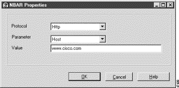
e. Click Add and add a second row of NBAR properties, as follows:
Click OK.
The NBAR Properties tab now shows the two filters you defined (Figure 3-36). By default, the Match ANY filter row AND ALL other conditions radio button is selected, therefore, packets must match both filters in order for the defined action to be carried out.
Step 3 Define the policy's queuing action, which ensures that the specified traffic receives a minimum percentage of the total bandwidth during times of congestion.
a. Click Next to open the Queuing Properties page.
b. Select the Queuing Properties check box.
The queuing properties fields are enabled.
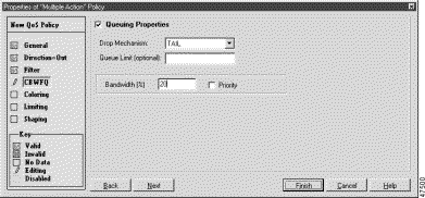
c. Type 20 in the Bandwidth field to ensure that the specified traffic receives a minimum of 20% of the total bandwidth when the line is congested (Figure 3-37).
Step 4 Define the policy's coloring action, which provides the specified traffic with high IP precedence.
a. Click Next to open the Coloring Properties page.
b. Select the Coloring Properties check box. The fields for the coloring properties become active.
c. Select flash-override(4) in the Precedence field to give high priority to the traffic that matches the defined NBAR properties.
Step 5 Define the policy's limiting action, which lowers the priority of the traffic if it exceeds a specific rate. This ensures that the specified traffic does not use more than its defined minimum bandwidth.
a. Click Next to open the Limiting Properties page.
b. Select the Limiting Properties check box.
The limiting properties fields are enabled.
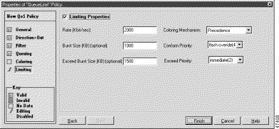
c. Define the following limiting properties:
Figure 3-38 shows the Limiting Properties page after you have defined all the properties.
d. Click Finish to save the policy.
Step 6  Click the Save button, or select File>Save, to save the policy in the database.
Step 7 Distribute your policy to the network, as described in Distributing Policies to the Network.
In this lesson, you will learn how to configure Frame Relay traffic shaping (FRTS) on Cisco routers. FRTS is frequently used to throttle traffic to the rate agreed upon with your WAN service provider, particularly if the destination link is running at a lower bandwidth than the source link.
For example, you might have a T1 line running at 1544 Kbps, but your service provider is committing to provide only 512 Kbps, and the destination of your traffic is a link running lower bandwidth than 1544 Kbps. By throttling the traffic rate at the source, you ensure that the traffic does not overwhelm the WAN link, resulting in dropped packets and increased delay. With FRTS, you can control the rate and smooth the traffic flow.
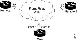
This example uses a different network setup than used in previous lessons. Figure 3-39 shows three routers connected over a Frame Relay cloud. All links are T1 Frame Relay lines. The Main router uses subinterfaces to enable routing between the two remote offices, Remote1 and Remote2. Most WAN traffic originates from the main office, so you will implement FRTS on the subinterfaces on the Main router. The service provider has committed to 512 Kbps for the Main-Remote1 link, and 256 Kbps for the Main-Remote2 link. There is no rate commitment for the interfaces on the remote links.
In this lesson, you will learn the following:
If you want to create a policy and deploy it on a device that exists in your network, obtain the IP address of an appropriate device. Otherwise, you can use the IP addresses in this lesson so that you can follow these steps without affecting your network.
This lesson assumes that you have completed the steps in previous lessons. Although you will not use the same network setup, you should already be familiar with adding devices and interfaces to the QoS database.
Table 3-8 lists the device details for this example. Because Remote1 and Remote2 links do not have a committed information rate, you are not enabling FRTS or other QoS capabilities on these routers in this example. Therefore, you only need to add Main, its Serial3/0 interface, and its subinterfaces to the database.
| Name | Device Model | Software Version | Interfaces | IP Address | Mask |
|---|---|---|---|---|---|
Main | 7200 | 12.1 | Serial3/0 T1 line at 1544 Kbit/second (Frame Relay) |
|
|
Serial3/0.1 Used as a permanent virtual circuit (PVC) with the Remote1 router, data link connection identifier (DLCI) 150. | 10.10.10.11 | 255.255.255.0 | |||
Serial3/0.2 Used as a PVC with the Remote2 router, DLCI 151. | 10.10.11.11 | 255.255.255.0 | |||
Remote1 | 4500 | 12.1 | Serial0 T1 line at 1544 Kbit/second (Frame Relay) | 10.10.10.10 | 255.255.255.0 |
Remote2 | 4500 | 12.1 | Serial0 T1 line at 1544 Kbit/second (Frame Relay) | 10.10.11.10 | 255.255.255.0 |
You must first enable FRTS on an interface in order to configure FRTS on the interface's subinterfaces or DLCIs.
Step 1 Add the Main router to the database, using 10.10.10.11 for the device name. See Lesson 1—Adding a Device to the QoS Database, for the steps for adding devices to the databases, if you are not familiar with the procedure.
Step 2 Enable FRTS on the Main router's Serial3/0 interface.
a. Right-click Serial3/0 in the 10.10.10.11 folder and select Interface Properties.
QPM opens the Properties of Interface dialog box.
b. Select FIFO as the QoS Property. You must select a QoS Property other than "Do Not Change" if you want to configure interface QoS capabilities such as FRTS.
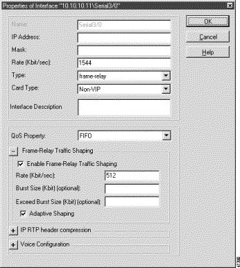
c. Select Enable Frame Relay Traffic Shaping.
d. Enter 512 in the Rate field.
e. Select Adaptive Shaping. This allows the interface to respond to notifications of congestion from the Remote1 and Remote2 routers, and throttle traffic accordingly.
Figure 3-40 shows the completed interface properties.
f. Click OK when finished.
You can choose to deploy FRTS on a subinterface or on a DLCI. This topic describes how to enable FRTS on the Main router's subinterfaces or DLCIs.
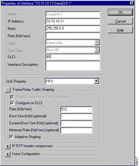
Step 1 Right-click Serial3/0.1 in the 10.10.10.11 folder and select Interface Properties.
Step 2 Make the following selections:
 |
Note If you want to configure FRTS on the DLCI, check the Configure on DLCI check box—otherwise FRTS will be configured on the subinterface. |
Figure 3-41 shows the completed interface properties. Click OK when finished.
Step 3 Use the same procedure to enable FRTS on the Serial3/0.2 subinterface, making the following interface selections:
 |
Note If you want to configure FRTS on the DLCI, check the Configure on DLCI check box—otherwise FRTS will be configured on the subinterface. |
Step 4  Click the Save button, or select File>Save, to save your changes.
Step 5 Distribute your settings to the network, as described in Distributing Policies to the Network.
QPM provides templates for configuring QoS for IP telephony in a separate database (IP_TELEPHONY_TEMPLATE). These templates are predefined device groups that contain the QoS configurations and policies required at each relevant point in the network. To use the IP telephony templates, all you need to do is add your devices to the database, then add the device interfaces to the relevant device groups and deploy the database. For detailed information about QPM IP telephony templates, refer to "Configuring QoS for IP Telephony."
 |
Note This lesson uses a different network configuration example than in previous lessons, and a separate QoS database. The lesson describes the whole process of configuring QoS for VoIP traffic, from adding the devices to the IP Telephony QoS database through deployment to the network. |
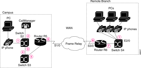
In this lesson, you will learn how to use IP Telephony templates to deploy QoS for VoIP over the Campus, WAN and Branch Office segments of a network, using the example network scenario illustrated in Figure 3-42.
This lesson includes the following topics:
Based on the network configuration example, the following sections describe:
The campus site includes a Cisco CallManager and IP Phone that are connected to a QoS-aware Catalyst 6000 access switch (S2). The IP Phone ports are configured to use an auxiliary voice VLAN (VLAN20) on S2. The Catalyst 6000 access switch is connected to a Catalyst 6000 distribution layer switch (S3). Voice data from the campus site enters the WAN from a Cisco 3600 router running IOS version 12.2.
In the campus site, you need to configure QoS at the following network points:
The following QoS features must be configured on the device interfaces in the WAN segment of the network (network points 6 in Figure 3-42):
The remote site includes several IP Phones on a LAN, connected via a Catalyst 3500 switch (S4) to a Cisco 3600 router (R6) in the WAN. QoS features must be configured on the IP Phones ports (network point 1) and on the branch office router interface to switch S4 (network point 7 in Figure 3-42).
This topic describes how to add the devices in the example network (see Figure 3-42) to the IP telephony database. The procedure in this example describes how to add router R5 from the network example. The procedure is identical for adding any network device. Refer to Table 3-9 for the technical details of the devices in the network example. You should perform this procedure also for router R6 and switches S2, S3 and S4.
 |
Note You can also add multiple devices at one time to the IP telephony database. Instead of adding each device individually, you can import a list of devices from a device inventory that was created using CiscoWorks2000 Resource Manager Essentials. See Importing Multiple Devices into the QoS Database, for details. |
Table 3-9 lists the technical details of the devices in the example network (see Figure 3-42) that you need to add to the IP Telephony database in order to follow this lesson.
| Device Name | Device Model and IP Address | Software Version | Interfaces |
|---|---|---|---|
R5 | 3600 | 12.2 | Serial1/0 Frame Relay line at 512 Kbit/sec Serial1/0.1 DLCI 40 |
Ethernet2/0 Standard Ethernet 10/100 Mbit/sec | |||
R6 | 3600 | 12.2 | Ethernet2/0 Standard Ethernet 10/100 Mbit/sec |
Serial3/0 Frame Relay line at 512 Kbit/sec Serial3/0.1 DLCI 40 | |||
S2 | Cat6000 | 6.2 | VLAN20 propVirtual |
Ethernet2/0 Standard Ethernet 10/100 Mbit/sec | |||
Ethernet2/1 Standard Ethernet 10/100 Mbit/sec | |||
Ethernet1/0 gigabitEthernet | |||
S3 | Cat6000 | 6.1 | Ethernet2/0 Standard Ethernet 10/100 Mbit/sec |
Ethernet1/1 gigabitEthernet | |||
S4 | Cat3500 | 12.0 | Ethernet 2/0 Standard Ethernet 10/100 Mbit/sec |
Ethernet 2/1 Standard Ethernet 10/100 Mbit/sec | |||
Ethernet 2/2 Standard Ethernet 10/100 Mbit/sec |
If you want to deploy QoS on a device that exists in your network, obtain the IP address of an appropriate device. Otherwise, you should use the IP addresses in this lesson so that you can follow these steps without affecting your network.
The IP_TELEPHONY_TEMPLATE database is read-only. In order to work with it, you must save it under a new name.
Step 1  Open and save the IP Telephony Database.
a. In the Policy Manager window, click the New IP Telephony Template button.
QPM opens the IP_TELEPHONY_TEMPLATE database window.
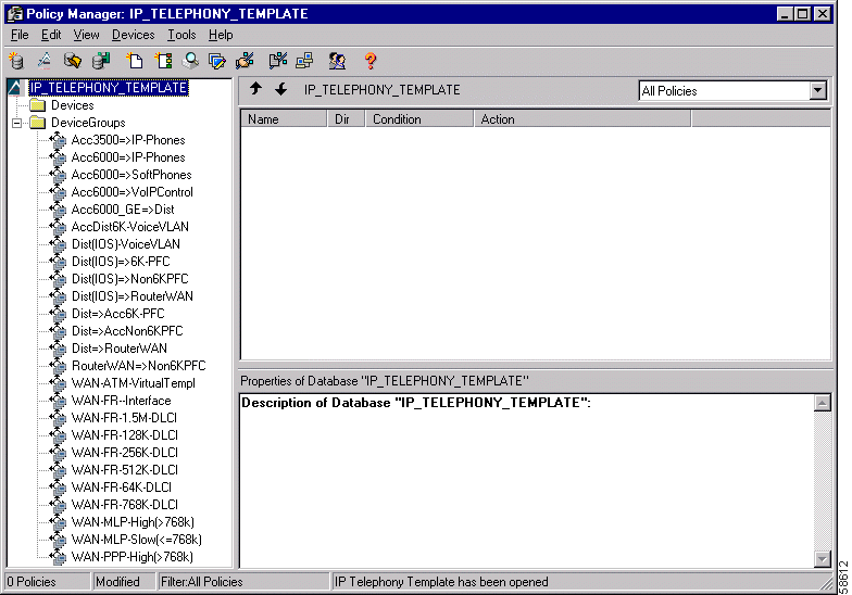
b. Select File>Save As and save the database under a new name. (For this Tutorial, save as Tutorial_IP_TELEPHONY_TEMPLATE).
Step 2 Add a device to the database.
a. Open the New Device dialog box by selecting Devices>Device>New in the Policy Manager.
b. Fill in the New Device dialog box.
At minimum, you must supply the following information:
In this example, router R5 is 10.1.1.1, the community string is public, and both passwords are test (Figure 3-44).
c. If your device is offline (for example, if you are using the IP addresses used in this lesson instead of addresses for devices on your network), you must select the device model and the mapped software version in the relevant fields. In this example, router R5 is a Cisco 3600 running IOS software version 12.2.
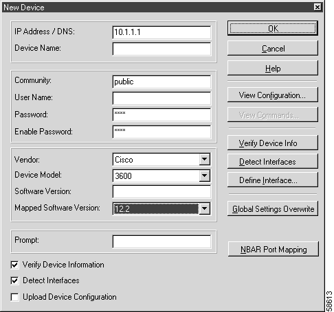
d. If the device is online and you want to add its interfaces automatically:
If you want to add interfaces manually to an offline or online device:
e. Click OK.
QPM creates a folder for the device (in this example, router R5) in the tree view using the IP address of the device.
Step 3 Add the device's interfaces.
a. If the device is online, QPM queries the device, fills in the Device Model and Software Version fields, and obtains a list of the device's interfaces.
 |
Note If the software version running on the device is not supported, QPM maps to the most similar supported version. This feature is described in Lesson 5Updating the Database After Software Upgrades. |
 |
Note If you want to apply QoS on switch S2's VLAN, make sure that the VLAN and all of its ports are in the selected interfaces list. |
b. If the device is offline:
 |
Note If you are entering details for a DLCI interface, a DLCI field becomes available once you enter the DLCI name. You should enter the appropriate DLCI number in this field (see Table 3-9). |
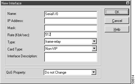
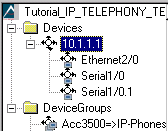
Step 4 Repeat steps 2 and 3 in order to add the interfaces for router R6, switch S2, switch S3 and switch S4 to the database.
This topic describes how to assign the interfaces that need QoS configuration for voice, to the appropriate device groups in the IP Telephony database.
 |
Note Non QoS commands that are not supported by QPM, such as power settings on ports and VLAN configuration, are beyond the scope of this Tutorial lesson. |
Based on the network example in Figure 3-42, assigning the interfaces to the Device Groups requires:
It is assumed that you have added routers R5 and R6, and switches S2, S3 and S4 and their respective interfaces to the Tutorial_IP_TELEPHONY_TEMPLATE database (see Figure 3-42). See Adding Devices to the IP Telephony Database.
To configure QoS for the IP Phone connection to the Catalyst 6000 access switch, you need to configure QoS for the ports and also the VLAN. Two device groups are available in the Policy Manager for this—Acc6000=>IP-Phones and AccDist6K=>VoiceVLAN. The Acc6000=>IP-Phones device group configures the trust state of the IP Phone and switch interface. The AccDist6K=>VoiceVLAN device group configures an ACL to trust all CoS classification on Ethernet ports in the VLAN.
The Acc6000=>IP-Phones device group configures the following features on the IP telephone port for the Catalyst 6000 access switch (S2):
Step 1 In the DeviceGroups folder of the Policy Manager tree view (Figure 3-43), right-click the Acc6000=>IP-Phones Device Group and select Add/Remove Members.
QPM opens the Add/Remove Members dialog box, displaying the available interfaces for IP Phone QoS configuration.
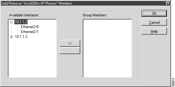
Step 2 Select the Ethernet2/1 port interface you added for switch S2 and click >> to add it to the Group Members area. Click OK.
QPM displays the following message, warning you that you will override the member interface's current QoS property with the group QoS property.
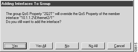
Step 3 Click Yes to continue to add the interface to the Device Group.
The selected interface is added to the Acc6000=>IP-Phones device group.

The AccDist6K=>VoiceVLAN device group configures the policies that should be applied to IP Phone interfaces that are configured to use VLAN-based QoS. This enables only the VLAN-based policies (not the individual port's policies) to be deployed to the ports on the VLAN.
Step 1 In the DeviceGroups folder of the Policy Manager tree view (Figure 3-43), right-click the AccDist6K=>VoiceVLAN device group and select Add/Remove Members.
QPM opens the Add/Remove Members dialog box, displaying the VLAN interface you added for switch S2.
Step 2 Select the VLAN20 interface and click >> to add it to the Group Members area. Click OK.
QPM displays a message, warning you that you will override the VLAN interface's current QoS property with the group QoS property.
Step 3 Click Yes to continue to add the interface to the device group.
The VLAN20 interface is added to the AccDist6K=>VoiceVLAN device group.
The IP Phone communicates with the CallManager using the Skinny Station Protocol. For example, when an IP Phone goes "off hook", it consults the CallManager, which then instructs the phone to play the dial-tone. In order to mark the importance of this control and management traffic between the CallManager and the IP Phone, ACLs are used to classify traffic streams on the Catalyst 6000 access switch.
The Acc6000=>VoIPControl device group in the Policy Manager enables you to configure QoS for the CallManager connection to the Catalyst 6000 access switch port, as follows:
Step 1 In the DeviceGroups folder of the Policy Manager tree view (Figure 3-43), right-click the Acc6000=>VoIPControl device group and select Add/Remove Members.
QPM opens the Add/Remove Members dialog box, displaying one of the Ethernet port interfaces you added for switch S2. (The other Ethernet2/1 interface is already assigned to the IP Phone connection.)
Step 2 Select the Ethernet2/0 port interface and click >> to add it to the Group Members area. Click OK.
QPM displays a message, warning you that you will override the Ethernet2/0 interface's current QoS property with the group QoS property.
Step 3 Click Yes to continue to add the interface to the device group.
The Ethernet2/0 interface is added to the Acc6000=>VoIPControl device group.
Once you have configured QoS on the IP Phone and CallManager interfaces, you must also configure the uplink interfaces to the Catalyst 6000 distribution switch (S3).
The Acc6000_GE=>Dist template enables you to configure the uplink ports on the Catalyst 6000 access switch to the distribution switch, as follows:
Step 1 In the DeviceGroups folder of the Policy Manager tree view (Figure 3-43), right-click the Acc6000_GE=>Dist device group and select Add/Remove Members.
QPM opens the Add/Remove Members dialog box, displaying the gigabitEthernet interface you added for switch S3.
Step 2 Select the Ethernet1/1 port interface and click >> to add it to the Group Members area. Click OK.
QPM displays a message, warning you that you will override the Ethernet1/1 interface's current QoS property with the group QoS property.
Step 3 Click Yes to continue to add the interface to the device group.
The gigabitEthernet type interface, Ethernet1/1, is added to the Acc6000_GE=>Dist device group.
You must also configure the downlink interfaces from the Catalyst 6000 distribution switch (S3) to the Catalyst 6000 access switch (S2).
The Dist=>Acc6K-PFC template enables you to configure the downlink ports on the Catalyst 6000 distribution switch to the access switch, as follows:
Step 1 In the DeviceGroups folder of the Policy Manager tree view (Figure 3-43), right-click the Dist=>Acc6K-PFC device group and select Add/Remove Members.
QPM opens the Add/Remove Members dialog box, displaying the gigabitEthernet interface you added for switch S2.
Step 2 Select the Ethernet1/0 port interface and click >> to add it to the Group Members area. Click OK.
QPM displays a message, warning you that you will override the Ethernet1/0 interface's current QoS property with the group QoS property.
Step 3 Click Yes to continue to add the interface to the device group.
The gigabitEthernet type interface, Ethernet1/0, is added to the Dist=>Acc6K-PFC device group.
The Dist=>RouterWAN device group in the Policy Manager enables you to configure QoS on the Catalyst 6000 distribution switch port to the WAN router (router R5 in the network example), as follows:
Step 1 In the DeviceGroups folder of the Policy Manager tree view (Figure 3-43), right-click the Dist=>RouterWAN device group and select Add/Remove Members.
QPM opens the Add/Remove Members dialog box, displaying the Ethernet port interface you added for switch S3.
Step 2 Select the Ethernet2/0 port interface and click >> to add it to the Group Members area. Click OK.
QPM displays a message, warning you that you will override the Ethernet2/0 interface's current QoS property with the group QoS property.
Step 3 Click Yes to continue to add the interface to the device group.
The Ethernet2/0 interface is added to the Dist=>RouterWAN device group.
In the Policy Manager, several device groups are available for configuring QoS on the Frame Relay WAN interfaces due to the different FRTS speeds.
For this example, you need to first configure the main Frame Relay interface using the WAN-FR-Interface device group and then configure the DLCI subinterface using the WAN-FR-512K-DLCI device group.
The WAN-FR-Interface device group enables you to configure FRTS on the main Frame Relay interfaces. This is a prerequisite for enabling FRTS on the DLCI subinterfaces.
Step 1 In the DeviceGroups folder of the Policy Manager tree view (Figure 3-43), right-click the WAN-FR-Interface device group and select Add/Remove Members.
QPM opens the Add/Remove Members dialog box, displaying the Serial interfaces you added for routers R5 and R6.
Step 2 Select each of the serial interfaces and click >> in turn to add it to the Group Members area. Click OK.
QPM displays a message, warning you that you will override the selected interface's current QoS property with the group QoS property.
Step 3 Click Yes to continue to add the interfaces to the device group.
The 10.2.1.1\Serial3/0 and 10.1.1.1\Serial1/0 interfaces are added to the WAN-FR-Interface device group.
The WAN-FR-512K-DLCI device group enables you to configure the QoS property, Class Based QoS, on the routers' DLCI subinterfaces. This QoS property includes CBWFQ and enables the configuration of the other QoS features for voice (see Configuring QoS for the WAN).
Step 1 In the DeviceGroups folder of the Policy Manager tree view (Figure 3-43), right-click the WAN-FR-512K-DLCI device group and select Add/Remove Members.
QPM opens the Add/Remove Members dialog box, displaying the DLCI subinterfaces you added for routers R5 and R6.
Step 2 Select each of the DLCIs and click >> in turn to add it to the Group Members area. Click OK.
QPM displays a message, warning you that you will override the selected interface's current QoS property with the group QoS property.
Step 3 Click Yes to continue to add the DLCI interfaces to the device group.
The 10.2.1.1\Serial3/0.1 and 10.1.1.1\Serial1/0.1 interfaces are added to the WAN-FR-512K-DLCI device group.
In the remote branch of the network, you need to configure QoS on the IP Phones ports and the branch office router R6 interface to access switch S4. For this example, you should use the Acc3500=>IP-Phone device group to configure the IP Phones ports, and then the RouterWAN=>Non6KPFC device group to configure the branch office router interface to switch S4.
The Acc3500=>IP-Phones device group configures the trust state as Trust-ext Untrusted on the IP phone ports and Catalyst 3500 access switch (S4) interfaces.
Step 1 In the DeviceGroups folder of the Policy Manager tree view (Figure 3-43), right-click the Acc3500=>IP-Phones device group and select Add/Remove Members.
QPM opens the Add/Remove Members dialog box, displaying the Ethernet interfaces you added for switch S4.
Step 2 Select each interface and click >> to add it to the Group Members area. Click OK.
QPM displays a message for each interface, warning you that you will override the interface's current QoS property with the group QoS property.
Step 3 Click Yes to continue to add the interfaces to the device group.
The Ethernet interfaces are added to the Acc3500=>IP-Phones device group.
The RouterWAN=>Non6KPFC device group in the Policy Manager enables you to configure QoS on the interfaces of the branch office router R6 interface to access switch S4.
Step 1 In the DeviceGroups folder of the Policy Manager tree view (Figure 3-43), right-click the RouterWAN=>Non6KPFC device group and select Add/Remove Members.
QPM opens the Add/Remove Members dialog box, displaying the Ethernet port interface you added for router R6.
Step 2 Select the Ethernet2/0 port interface and click >> to add it to the Group Members area. Click OK.
QPM displays a message, warning you that you will override the Ethernet2/0 interface's current QoS property with the group QoS property.
Step 3 Click Yes to continue to add the interface to the device group.
The Ethernet2/0 interface is added to the RouterWAN=>Non6KPFC device group.
In order to distribute the QoS policies you have configured in the network example to your network devices, you must deploy the IP Telephony database to the network. The Distribution Manager enables you to do this. Refer to Starting Distribution Manager, for a full description of how to deploy a database with configuration policies to network devices.
 |
Note You can preview the device (CLI) commands that the Distribution Manager will use to configure the devices, using the Devices>View Commands option in the Distribution Manager. See Viewing the Configuration Commands for a Device, for details. |
![]()
![]()
![]()
![]()
![]()
![]()
![]()
![]()
Posted: Tue Nov 12 12:41:28 PST 2002
All contents are Copyright © 1992--2002 Cisco Systems, Inc. All rights reserved.
Important Notices and Privacy Statement.