|
|

This chapter presents a tutorial describing how to display a baseline topology and how to use the features available in the Topology window. The Topology window presents a visual representation of a network represented by a baseline. The Topology window is used in conjunction with other Connectivity Tools features to accomplish the tasks described in this tutorial. Refer to "Creating and Opening a Baseline" for information on how to create and load a baseline into the baseline model.
This tutorial describes how to:
Step 1 Display a baseline topology.
Step 2 Search for a specific device within the topology:
Step 3 Display the attributes of a router.
Step 4 Zoom in on a particular topology area.
Step 5 Print the topology.
Step 6 Display IP or IPX routes in the topology.
Having proceeded through the steps of creating and opening a baseline, as described in the first tutorial, the Connectivity Tools window, shown in Figure 3-1, is displayed.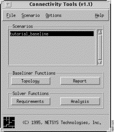
Step 1 Click on the Topology button.
By default, the tutorial_baseline topology is displayed as a campus IP view in the Topology window, as shown in Figure 3-2.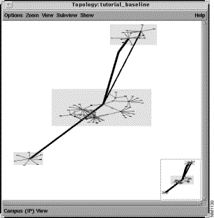
To display the topology in a flat view, as shown in Figure 3-3, select the View>Flat menu option.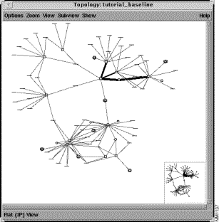
Various options are available, via the Show menu, for determining the display characteristics of the Topology window. Network element names/addresses, links, campus labels, terminal LANs, a summary map, a Status Bar, and mouse button functions can all be displayed, or not, depending on the Show menu options selected. The color scheme and fonts used in the Topology window can also be modified by selecting the Options>Preferences menu option. See Chapter 4, "Creating the Topology," in the Enterprise/Solver Connectivity Tools Reference Guide for detailed information about the menu options provided within the Topology window.
A device can be located within the Topology window in one of the following ways:
Step 2 Select the Options>Find Device menu option in the Connectivity Tools window.
The Find Device window, as shown in Figure 3-4, is displayed when you click on the Search button with the default selections in effect. A search for all routers known by the current baseline is performed with the default options in effect. The known routers are displayed in the Results list.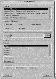
Step 3 Select the netsys5 router entry in the Results list.
The netsys5 router icon is highlighted in the Topology window, as shown in Figure 3-5.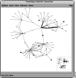
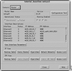
Step 4 To view or modify the netsys5 router attributes, double-click on its highlighted router icon.
The Router Configuration window is displayed, shown in Figure 3-6. To display the attributes of a LAN element, double-click on a LAN element icon. To display the attributes of a Link segment, double-click on a link segment icon. To make it easier to know when the cursor is over a particular device, the device name or element address is displayed in the Status Bar in the Topology window. When the name/address is present, double-click to display the corresponding Router/LAN/Link/End System Configuration window.
An alternative method for displaying a network element configuration window is to select the desired network element entry in the Find Device window's Results list, then click on the Parameters button.
When using the Connectivity Baseliner, the network element attributes can only be viewed. When using the Connectivity Solver, the network element attributes can be modified, as well as viewed. To modify network element attributes and connectivity requirements, the following restrictions exist:
Step 5 Select the Zoom>In menu option.
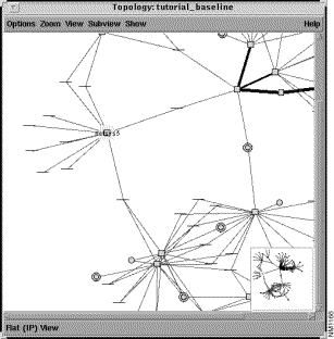
The Topology window is redrawn as shown in Figure 3-7. To zoom in on a specific area in the topology, use this option or double-click MENU in the desired area in the Topology window. Draw a bounding box around the specific area to focus on (zoom in option.) Click ADJUST to display the area within the bounded box in a smaller scale (zoom out option.) Double-click MENU to display the entire topology within the Topology window (all to fit option.)
Step 6 Select the Options>Print menu option.
The Print Options window, shown in Figure 3-8, is displayed. The topology can be printed to a file (in PostScript format) and/or to a PostScript printer using the default print command.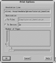
Step 7 Click on the To Device button, specify a print command if different from the default, then click on the OK button.
A copy of the topology is sent to the default PostScript printer using the lp print command.
Step 8 Select the Subview>IPX menu option to display the IPX paths in the Topology window, as shown in Figure 3-9.
Click on the Subview>IP menu option to display the IP paths again.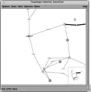
When using the Connectivity Solver, the Requirements Analysis and Round Trip Path windows can be used to locate a router and display paths in the Topology window. To use the Round Trip Path window to locate a network element, connectivity requirements must be viewed or created. The details of viewing and creating connectivity requirements are described in "Round Trip IP Connectivity Requirements."
|
|