|
|

This chapter provides a tutorial on using the Connectivity Tools topology drawing capabilities to customize your topology layout.
The following tasks are performed and described in this tutorial:
Having proceeded through the steps of creating and opening the tutorial_baseline baseline, as described in the first tutorial, the Connectivity Tools window, shown in Figure 4-1, is displayed. See "Creating and Opening a Baseline" for information on how to create and open a baseline.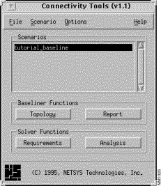
Step 1 Click on the Topology button in the Connectivity Tools window.
By default, the baseline topology is displayed as a campus view in the Topology window, as shown in Figure 4-2.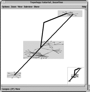
Step 2 Zoom in on the campus in the upper-right corner of the Topology window by dragging a bounding box around it.
Press on the right mouse button while dragging the cursor around the campus, then release. The bounding box drawn around the campus you want to zoom in on is shown in Figure 4-3.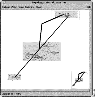
The Topology window now displays an enlarged view of the selected campus (C1_net), approximating the view shown in Figure 4-4.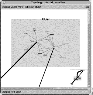
Step 3 Move the Ethernet LAN segment icons between the two displayed routers.
This is accomplished by pressing over an icon with the left mouse button and then dragging the cursor to the new desired location. Notice the move cursor (cross-hair with arrows) that is displayed when an object is selected for movement. Move each of the Ethernet LAN segment icons so they appear as shown in Figure 4-5.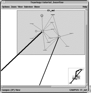
Step 4 Move the right-most router icon further to the right.
Select and drag the router icon as shown in Figure 4-6. Notice the blue (logical link) and black (serial link) lines stretch to the router's new location.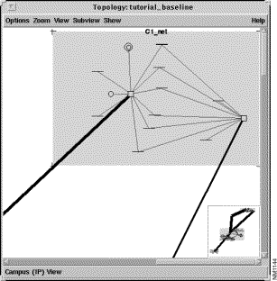
LAN segment and router icons can be moved individually in this manner to reduce clutter or arrange a topology into a custom layout.
Step 5 Double-click on the right mouse button or select the Zoom> All to Fit menu option to view the entire topology again.
Step 6 Click on the right mouse button somewhere within the grey region that makes up the central (large) campus. Select the Rename menu option from the pop-up menu.
The Rename Window, shown in Figure 4-7, is displayed. Replace the current name, C3_net, with the new name: Main_Campus.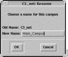
Step 7 Select the Show>Campus Labels menu option and confirm that the new campus name is displayed.
Step 8 Zoom in on the campus C4_net by dragging a bounding box around it.
The zoom region is shown in Figure 4-8. 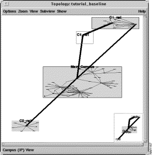
The Topology Window now displays an enlarged view of the C4_net campus, approximating the view shown in Figure 4-9. Notice the campus contains only one router, and no LAN segments.
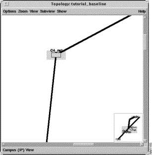
The default campus view is arranged such that serial links separate campuses. In the case of the C4_net campus, the single router displayed does not have any LAN interfaces. It only has serial interfaces and thus is placed in its own campus.
In customizing a topology, it may be useful to show this router belonging to a specific campus or physical location. For example, in this baseline, it may be useful to represent the netsys9c router in the C4_net campus as residing within the C1_net campus. This is done in the following steps.
Step 9 Click on the right mouse button in the grey area defining the C4_net campus, being careful not to click over the netsys9c router icon.
Step 10 Select the Remove Campus option from the pop-up menu.
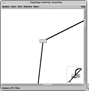
The grey campus box vanishes, leaving just the netsys9c router icon, as shown in Figure 4-10.
Step 11 Click on the middle mouse button or select the Zoom>Out menu option until the campus in the upper-right corner of the window is visible.
Step 12 Move the netsys9c router icon into the upper right campus (C1_net). Double click on the right mouse button or select the Zoom>All to Fit menu option.
All of the topology is now displayed within the Topology window as shown in Figure 4-11.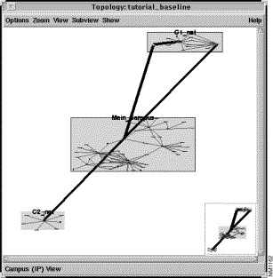
Step 13 Move the C1_net campus to the left.
Position the cursor within the grey region defining the C1_net campus, without contacting any of the router or LAN icons. Press on the left mouse button, then move the entire campus to a position as shown in Figure 4-12. Notice all routers and LAN segments within the campus move with it, and the serial links are stretched to the new campus location.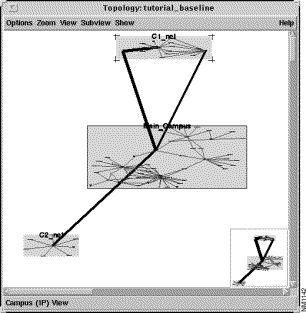
Step 14 Resize the C1_net campus.
Select the C1_net campus by clicking on the right mouse button with the cursor within the grey region defining the campus. Notice the resize brackets that appear at the campus corners. Move the cursor towards one of the lower corners of the campus until it changes into the resize (angle bracket) cursor. Press on the left mouse button, then drag to a new position to resize the campus, as shown in Figure 4-13.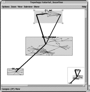
Resizing a campus is useful for clearing clutter in a topology, or expanding to make room for additional or existing devices. For example, the Main_Campus campus might be resized and the devices within it distributed further apart for clarification (although this tutorial does not go through such an exercise.)
Step 15 Create a new campus.
Click on the right mouse button in the empty area in the upper left corner of the Topology window. Select New Campus from the pop-up menu. An empty campus is displayed, as shown in Figure 4-14.
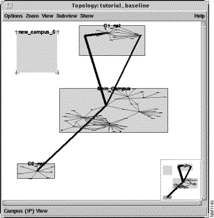
As mentioned previously, the default campus view creates a campus for routers separated by a serial link. To clarify a topology, it may be useful to further separate routers and devices so they better approximate an enterprise's actual physical network layout. A new campus might be added to represent a unique site, and the routers belonging to that site moved into the new campus.
In this tutorial, the netsys9c router is moved into a newly created campus.
Step 16 Locate router netsys9c in the topology (the router that was moved into the C1_net campus previously.) Move it into the new campus.
The topology is now displayed as shown in Figure 4-15.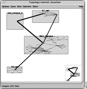
Step 17 Select the Options>Save Layout menu option.
Subsequent uses of this tutorial_baseline will display the newly modified topology. To remove the changes you have made to the topology you can:
|
|