|
|

This chapter presents a tutorial describing how to start the Connectivity Tools, create a new baseline, load a baseline into memory, and save the baseline router configuration files to a specified directory. This tutorial is used as the basis for all other tutorials presented in this document. In actual work environments, prior to starting the Connectivity Tools, access to the network's router configuration files is needed. Methods for retrieving your actual router configuration files are outside the scope of this tutorial. Therefore, sample router configuration files (located in the install_directory/sample_configs directory) are provided and used by this tutorial.
We recommend you proceed through this tutorial with the Connectivity Baseliner or Connectivity Solver running.
This tutorial describes how to:
Step 1 Copy the sample router configuration files to another directory.
Sample router configuration files are provided in the install_directory/sample_configs directory. install_directory is the directory where the Connectivity Tools were installed. These files, or your own router configuration files, can be used. Using the sample router configuration files makes following the tutorials easier, as the tutorials are based on these files.
Step 2 Set the environment variables referenced by the Connectivity Tools.
Prior to running the Connectivity Tools, the environment variables described in the Enterprise/Solver Connectivity Tools READ THIS FIRST (RTF) must be set.
Step 3 Start the Connectivity Baseliner and Connectivity Solver with the following command:
host% install_directory/ctk |
The Connectivity Tools window, shown in Figure 2-1, is displayed.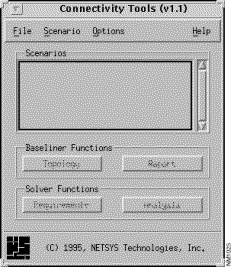
Step 4 Select the File>New Baseline menu option to create the new baseline.
The New Baseline window, shown in Figure 2-2, is displayed. Within this window specify the name of the new baseline, the source directory where the router configuration files are located, and the destination directory where the baseline is to be created.
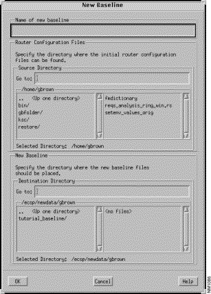
Step 5 Specify the name of the new baseline in the Name of new baseline field.
Name the baseline tutorial_baseline.
Step 6 Specify the name of the directory where the router configuration files are located in the Source Directory Go to field.
Step 7 Specify the name of the directory where the new baseline files are to be placed in the Destination Directory Go to field.
The directory used in this tutorial is /ecsp/newdata/gbrown. Specify all or part of the directory path in the Destination Directory Go to field, then press Return. If part of the directory path is specified, navigate to the desired directory by double-clicking on an entry until the desired location is reached. The default location is the directory specified by the ECSP_DATA environment variable.
Step 8 Click on the OK button to create the new baseline directory and to copy and place under SCCS control, the source router configuration files to that directory.
The Connectivity Tools window is again displayed. The File>Open Baseline, File>New Baseline, File>Delete Baseline, and File>Exit menu options are the only activated window components as the newly created baseline (tutorial_baseline)has not been loaded into memory at this time. To load a baseline into memory thus creating the baseline model, use the File>Open Baseline option.
Step 9 Select on the File>Open Baseline option.
The Open Baseline window, shown in Figure 2-3 is displayed. The directory location displayed in the Data Directory field is the directory specified by the ECSP_DATA environment variable.
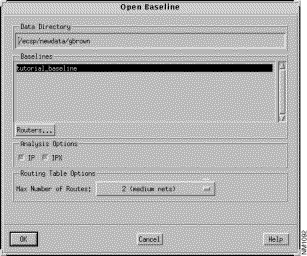
Step 10 Select the router protocol(s) to be analyzed by selecting the IP and IPX options.
The IP and IPX Analysis options buttons are not available with the Connectivity Baseliner. When using the Connectivity Solver, the IP and IPX buttons are selected by default. Selecting just one of the protocols cuts down on the amount of time spent doing the initial routing protocol analysis. This is useful if your network supports only one routing protocol or if analysis of only one protocol is desired. Both protocols will be selected for this tutorial.
Step 11 Select the maximum number of routes to be calculated, per Routing Table.
Four Routing Table Options exist. The default will be used for this tutorial (a maximum of two routes per Routing Table will be calculated.) The maximum is four but you must be very careful when selecting this option as it is very processing time and memory intensive.
Step 12 Select the tutorial_baseline entry then click on the OK button.
The tutorial_baseline's router configuration files are parsed (semantic and syntax checks are made), the tutorial_baseline baseline is loaded into memory creating a baseline model, and a topology of the baseline is created in memory.
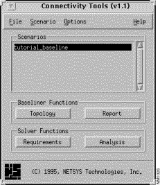
Information in the Connectivity Tools window, shown in Figure 2-4, is updated and the tutorial_baseline scenario is created and its entry displayed and selected in the Scenarios list. The initial baseline scenario created when a baseline is loaded into memory is given the name of the baseline, in this case tutorial_baseline. The initial scenario is used to display the baseline topology, format and display the Diagnostic Report generated by the parser process, and view (not modify) existing router, LAN, link, and End System attribute settings, as well as static route, default network, and routing algorithm information. Using the Connectivity Solver, the initial scenario can also be used to create and view connectivity requirements for a particular baseline. This functionality is not available with the Connectivity Baseliner. Therefore, the Requirements button is not activated.
In order to change router configuration attributes for "what-if" scenario simulations, a new scenario must be created from the initial scenario. This functionality is not available with the Connectivity Baseliner. Therefore, the Analysis button is not activated. All of the window's buttons and menu options are activated when using the Connectivity Solver.
See subsequent tutorials presented in this document for information on displaying a topology, generating the Diagnostic Report, and using the Connectivity Solver's features to create "what-if" scenarios and view, modify and analyze network connectivity requirements.
Step 13 Select the File>Export Baseline option.
The Export Baseline window, shown in Figure 2-5 is displayed. This option saves the tutorial_baseline router configuration files to the specified directory. This is especially useful when router configuration files have been modified. The exported router configuration files can then be used in another program or with actual routers in the work environment.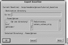
Step 14 Specify the name of the directory where the baseline router configuration files are to be saved in the Go to field, then press Return.
Your home directory is the default directory. A list of the directories (left pane) and files (right pane) residing in the current directory are displayed. Specify the desired location in the Go to field then press Return, or navigate to the desired directory from within the directory pane by double-clicking on a directory entry to move to that location.
Step 15 Click on the OK button to save the baseline router configuration files to the directory specified.
|
|