|
|

This tutorial describes how to check a baseline's existing IP connectivity requirements, as well as how to create new IP connectivity requirements for a baseline. Checking and modifying connectivity requirements can be accomplished using the initial baseline scenario created when a baseline is opened and loaded. Therefore, creating a new scenario is not required for this tutorial. This tutorial is used as the basis for subsequent tutorials in this document.
The following tasks are performed and described in this tutorial:
Step 1 From the Open Baseline window, select the tutorial_baseline baseline. Click on the OK button to load the tutorial_baseline baseline and create the baseline scenario.
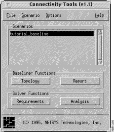
Refer to "Creating and Opening a Baseline" for information about creating and opening a baseline. In this tutorial, the baseline (tutorial_baseline) created in the first tutorial is used. Figure 7-1 shows the Connectivity Tools window after the tutorial_baseline baseline was opened and loaded. By default, when a baseline is opened, an initial baseline scenario is created. It has the same name given to the baseline and is displayed and selected in the Scenarios list.
Step 2 Click on the Topology button in the Connectivity Tools window.
The tutorial_baseline scenario's topology is displayed in a campus IP view (the default) in the Topology window.
Step 3 Select the View>Flat menu option in the Topology window.
The topology is displayed in a flat IP view, as shown in Figure 7-2.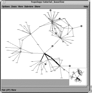
Step 4 With the tutorial_baseline scenario selected in the Connectivity Tools window's Scenarios list, click on the Requirements button.
To create end system connectivity requirements, the Requirements feature is used. Connectivity requirements are created, viewed, loaded, unloaded, deleted, and undeleted using this feature. The Requirement Sets window is displayed, as shown in Figure 7-3.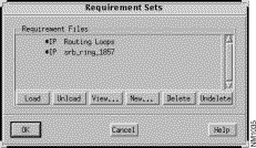
A list of network connectivity requirement file sets, if any exist, containing the connectivity requirements for the tutorial_baseline scenario, is displayed in the Requirement Files list.
Requirement File entries preceded by an asterisk indicate connectivity requirements implicitly derived from the router configuration files. These connectivity requirement file sets can not be edited or deleted.
The implicitly derived Routing Loops requirement set is provided to find routing loops caused by IP redistribution. When you select the Routing Loops requirement set and then load it for analysis by clicking on the Load button followed by the OK button, a list of all the redistribution IP routing loops detected during analysis is displayed in the Requirements Analysis window. The results are a set of paths showing the identified routing loops. Each path displays a source address set to a port address of a router involved in the loop and a destination, which is a subnet or end point address, identifying the Routing Table destination involved in the routing loop. The path also shows a set of routers involved in a loop.
Step 5 Click on the New button.
The New Requirement Set window, shown in Figure 7-4, is displayed. Create a new set of protocol dependent (in this case IP) connectivity requirements and save them to the file specified in this window.
Step 6 Specify tcp_telnet_test in the Name field, then click on the OK button.
A name must be assigned to the new set of IP connectivity requirements. By default, IP is selected as the requirement type.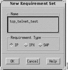
Upon clicking on the OK button, the Requirements window is displayed. No requirements are defined in the tcp_telnet_test requirement set as yet, therefore the Requirements pane is empty.
Step 7 Click on the Add button in the Requirements window.
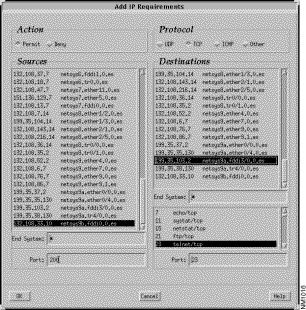
The Add IP Requirements window, shown in Figure 7-5, is displayed. New requirements to the tcp_telnet_test requirements set are created using this window. Allow (Permit button selected) a TCP/Telnet connection from port 200 of source end system netsys9b.fddi0.0.es (selected from the Sources list) to port 23 (automatically specified in the Destinations Port field when the telnet/tcp entry is selected from the list) of destination end system netsys9a.fddi3/0.0.es (selected from the Destinations list). The default transport control protocol is TCP.
Step 8 Click on the OK button to add the new requirements.
The newly defined requirement entry is now displayed in the tcp_telnet_test file's requirements as partially shown in the modified Requirements window in Figure 7-6.
Step 9 Click on the OK button to create the tcp_telnet_test requirement file set.
The Requirement Sets window now displays the tcp_telnet_test file name entry in the Requirement Files list, as shown in Figure 7-7.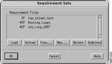
Step 10 Select the tcp_telnet_test file set from the Requirement Files list then click on the Load button followed by the OK button.
The tcp_telnet_test connectivity requirements are loaded for analysis. The results of the analysis are viewed from the Requirements Analysis window, partially shown in Figure 7-8. That is, the status of each connectivity requirement loaded for analysis, can be viewed. In this case, one path was found between the two end systems (netsys9b.fddi0.0.es and netsys9a.fddi3/0.0.es). To view the entire contents of the window, use the horizontal slider bar.
When multiple paths are found, the entries can be sorted by status (default), number of routes, source and destination names, and source and destination addresses. The Filter field can be used to locate and display entries whose type, status, source or destination names, source or destination addresses, or destination port values match the value specified in this field.
Step 11 Select the lone entry to highlight the route between the two end systems in the Topology window, as shown in Figure 7-9.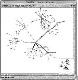
The thicker highlighted line represents the route from the source router (netsys9b) to the destination router (netsys9a). The thinner highlighted line represents the return path from the destination router (netsys9a) to the source router (netsys9b).
Step 12 Double-click on the selected connectivity requirement entry in the Requirements Analysis window.
A corresponding Round Trip Path window is displayed, as shown in Figure 7-10. This window provides the end system names, addresses, and ports, the current status of the path, and a list of the devices and network elements that make up the path from the source end system to the destination end system. Selecting an entry in the Round Trip Path list highlights that network component's icon and displays its name and/or network address in the Topology window. Based on the information provided in this and the Topology windows, the current connectivity requirements can be identified, from not only a component standpoint, but visually as well.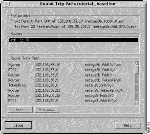
Step 13 Start with the first entry listed in the Round Trip Path list then click on each subsequent entry or the Next button.
Do this with the Topology window displayed to follow the route from the source router to the destination router. Upon reaching the destination router, the "Reached destination-turn around" message is displayed in the Round Trip Path list. Continuing the process follows the return path from the destination router back to the source router.
|
|