|
|

Table Of Contents
Install the Bay and Backplane Connections
F1 Unpack and Verify the Bay Assembly
F3 Drill Holes to Anchor and Provide Access to the Bay Assembly
F4 Install the Dollies onto the Bay Assembly
F8 Replace the Existing 23.622 inches (600-mm) Kick Plates with 35.43 inches (900-mm) Kick Plates
F10 Connect the Office Ground to the ONS 15600 SDH
F11 Connect the PDU Ground Cables to the PDU
F12 Install Isolated Logic Ground
F13 Connect Office Power to the ONS 15600 SDH Bay
F14 Route and Terminate Raised-Floor Power Cables
F17 Install Alarm Wires on the CAP
F18 Install E1 (100 Ohm) Timing Connections on the CAP
F19 Install LAN Cables on the CAP
F20 Install the TL1 Craft Interface Cable
F21 Inspect the Bay Installation and Connections
Install the Bay and Backplane Connections
This chapter provides procedures for installing the CiscoONS15600SDH shelf assembly. To view a summary of the tools and equipment required for installation, see the "Required Tools and Equipment" section .
Before You Begin
This section lists the chapter procedures (NTPs). Turn to a procedure for applicable tasks (DLPs). Perform these procedures in the order they appear.
1.
F1 Unpack and Inspect the CiscoONS15600SDH Bay Assembly—Complete this procedure before continuing with the "NTP-F2 Install the Bay Assembly" procedure.
2.
3.
4.
5.
6.
7.
Warning
Warning
Warning
Warning
Required Tools and Equipment
You will need the following tools and equipment to install and test the ONS15600SDH.
Included Materials
The ONS15600SDH bay ship kit is shipped with the ONS15600SDH system. The under-floor power kit is an optional item and is used in environments where power is supplied through the floor, rather than over head. You can also order installation dollies to help you with unloading the bay from the shipping pallet; for information about obtaining the dollies contact your Cisco sales engineer.
The number in parentheses gives the part number or the quantity of the item included in the package.
•
–
–
–
–
–
•
–
–
–
–
•
–
–
–
–
–
•
–
–
–
–
•
–
–
–
–
•
–
–
–
User-Supplied Materials
The following materials and tools are required but are not supplied with the ONS15600SDH:
•
•
•
•
•
•
•
•
•
•
•
•
Tools Needed
•
•
•
•
•
•
•
•
•
•
•
•
•
•
Test Equipment
•
•
•
NTP-F1 Unpack and Inspect the Cisco ONS 15600 SDH Bay Assembly
Step1
Step2
Step3
Stop. You have completed this procedure.
DLP-F1 Unpack and Verify the Bay Assembly
Warning
Step1
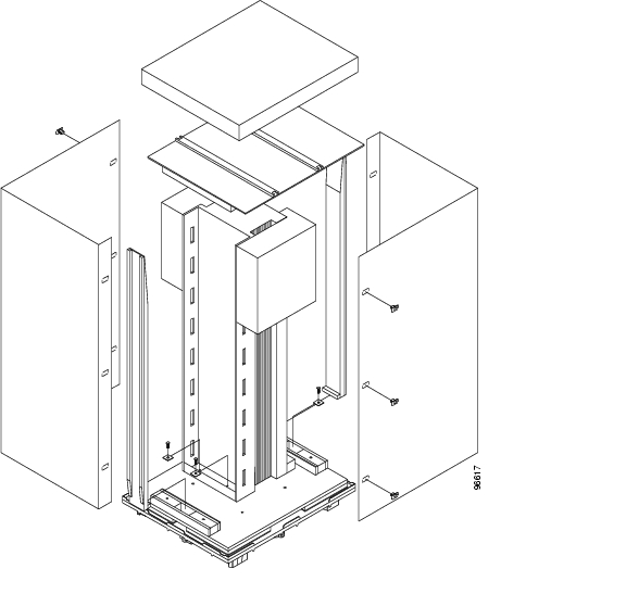
Figure 1-1 shows the packaging you must remove from the ONS 15600 SDH.
Figure 1-1 ONS 15600 SDH Bay Assembly Packaging
Step2
Step3
Step4
Step5
Step6
Step7
Step8
Step9
Step10
DLP-F2 Inspect the Bay Assembly
Purpose
This task verifies that all parts of the bay assembly are in good condition.
Tools/Equipment
None
Prerequisite Procedures
Required/As Needed
Required
Onsite/Remote
Onsite
Security Level
None
Step1
Step2
Step3
Step4
Step5
NTP-F2 Install the Bay Assembly
Warning
Warning
Step1
Step2
Step3
Step4
Stop. You have completed this procedure.
DLP-F3 Drill Holes to Anchor and Provide Access to the Bay Assembly
Note
Step1
a.
b.
Note
Figure 1-2 Floor Template
Step2
Step3
Step4
Step5
Step6
Step7
Step8
Step9
Step10
DLP-F4 Install the Dollies onto the Bay Assembly
Note
Step1
Step2
Step3
Step4
Note
Step5
Step6
Step7
Step8
Step9
Figure 1-3 ONS 15600 SDH with Dollies Installed
Step10
DLP-F5 Install the Bay Assembly
Purpose
This task explains how to install the bay assembly at the installation site.
Tools/Equipment
Ratchet
6-inch (or greater) ratchet extension (optional)
Socket wrench
Torque wrench
Phillips screwdriver, 6 inches long
23.62-inches (600-mm) kick plate kit (53-2177-XX), or 35.4-inches (900-mm) kick plate kit (53-2178-XX)
Rectangular seismic washers (4) (53-2141-XX)
5/8-inch floor anchor bolts (4)
Prerequisite Procedures
F1 Unpack and Inspect the CiscoONS15600SDH Bay Assembly
F3 Drill Holes to Anchor and Provide Access to the Bay Assembly
Required/As Needed
Required
Onsite/Remote
Onsite
Security Level
None
Note
Step1
Step2
Step3
Step4
Note
Step5
Step6
Step7
a.
b.
Step8
NTP-F3 Open and Remove the Front Door
Note
Step1
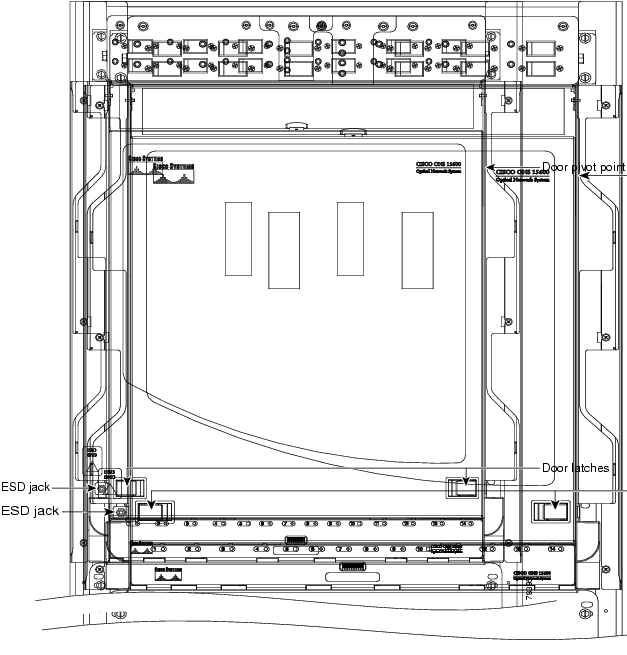
Figure 1-4 ONS 15600 SDH Front Door
Step2
Step3
Step4
Step5
Stop. You have completed this procedure.
NTP-F4 Install Cable Routing Modules and Kick Plates
Note
Note
Step1
Step2
Step3
Step4
Step5
Stop. You have completed this procedure.
DLP-F6 Install the Narrow CRMs
Step1
Step2
Step3
Step4
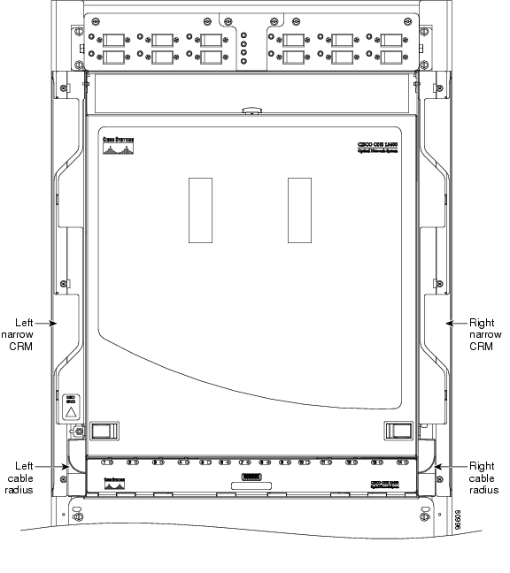
Figure 1-5 Narrow CRMs
Step5
DLP-F7 Remove the Narrow CRMs
Step1
Step2
Step3
Step4
Step5
DLP-F8 Replace the Existing 23.622 inches (600-mm) Kick Plates with 35.43 inches (900-mm) Kick Plates
Step1
Step2
Step3
Step4
Note
Step5
Step6
DLP-F9 Install the Wide CRMs
Note
Note
Step1
Step2
Step3
Step4
Step5
Note
Step6
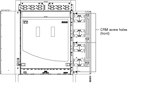
Figure 1-6 CRM Screw Holes (Front)
Step7
Step8
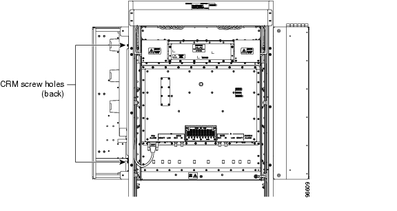
Figure 1-7 CRM Screw Holes (Rear)
Step9
Step10
NTP-F5 Install the Bay Power and Ground
Warning
Warning
Warning
Caution
Warning
Warning
Step1
Step2
Step3
Step4
Step5
Step6
Step7
Step8
Stop. You have completed this procedure.
DLP-F10 Connect the Office Ground to the ONS 15600 SDH
Warning
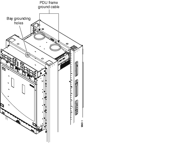
Step1
Figure 1-8 PDU Ground Cables and Grounding Holes
Step2
Step3
Step4
DLP-F11 Connect the PDU Ground Cables to the PDU
Step1
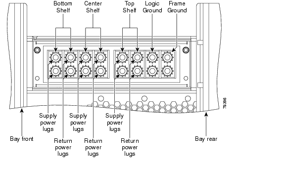
Note
Figure 1-9 Power Terminal Block (Right Side Shown)
Step2
Step3
Step4
Step5
DLP-F12 Install Isolated Logic Ground
Step1
Step2
Step3
Step4
Step5
Note
Step6
Step7
Step8
Step9
Step10
DLP-F13 Connect Office Power to the ONS 15600 SDH Bay
Warning
Caution
Note
Step1
Step2
Note
Caution
Caution
Step3
Step4
Step5
Note
Step6
Note
Step7
Step8
Step9
Step10
Step11
DLP-F14 Route and Terminate Raised-Floor Power Cables
Purpose
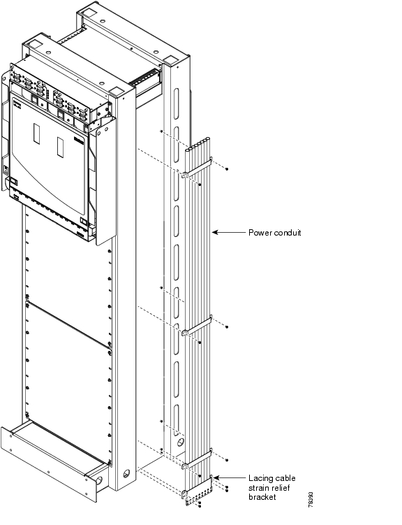
This task installs the power conduit included in the raised-floor power kit and routes and terminates the power cables.
Tools/Equipment
Screwdriver
Ground cables, rated for at least 125-A capacity
Two-hole power lugs, 0.625-inch hole spacing; 0.25-inch bolt holes (Panduit LCCF2-14AZFW-E) (for underfloor-routed power cables) (16)
Note
Raised-floor power kit (800-23062-XX), which includes:
•
•
•
•
•
Prerequisite Procedures
F10 Connect the Office Ground to the ONS15600SDH
Required/As Needed
As needed for bays installed in a raised-floor environment where the power cables originate from the floor.
Onsite/Remote
Onsite
Security Level
None
Step1
Step2
Step3
Figure 1-10 Installing the Power Conduit in a Raised-Floor Power Environment
Step4
Step5
Step6
Step7
Step8
Step9
Step10
Step11
Step12
Step13
DLP-F15 Verify Office Power
Purpose
This task measures the power to verify correct power and returns.
Tools/Equipment
Voltmeter
Prerequisite Procedures
F10 Connect the Office Ground to the ONS15600SDH
Required/As Needed
Required
Onsite/Remote
Onsite
Security Level
None
Step1
Step2
Step3
Note
Step4
Step5
Step6
Step7
Step8
Step9
Step10
DLP-F16 Verify Fan Operation
Warning
Step1
Figure 1-11 ONS 15600 SDH Shelf with One Fan Tray and Air Filter Removed
Step2
Step3
Step4
NTP-F7 Install Wires to Alarm, Timing, LAN, and Craft Pin Connections
Step1
Step2
Step3
Step4
Step5
Caution
Step6
Step7
Stop. You have completed this procedure.
DLP-F159 Remove the Rear Cover
Purpose
This procedure removes the rear cover to provide access to the CAP.
Tools/Equipment
None
Prerequisite Procedures
Required/As Needed
Required
Onsite/Remote
Onsite
Security Level
None
Step1
Step2
Step3
Step4
Stop. You have completed this procedure.
DLP-F17 Install Alarm Wires on the CAP
Step1
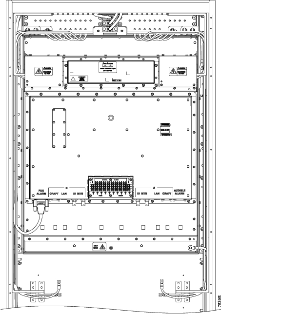
Figure 1-12 Rear of the ONS 15600, Including the CAP
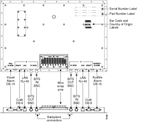
Figure 1-13 shows the CAP faceplate in detail.
Figure 1-13 CAP Faceplate and Connections
Note
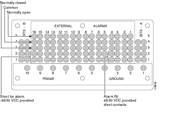
Figure 1-14 shows alarm pin assignments.
Figure 1-14 Alarm Pin Assignments on the CAP
See "Manage Alarms" for instructions on assigning alarms to these pins.
Lace or tie wrap cables to the tie wrap features that are located below the connector pattern, according to local site practice.
Step2
Step3
DLP-F18 Install E1 (100 Ohm) Timing Connections on the CAP
Step1
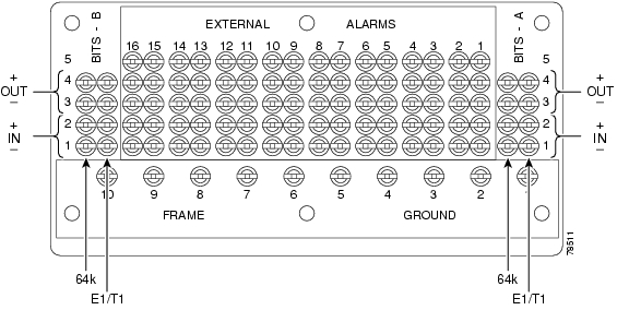
Figure 1-15 shows the location of the timing connections on the pin field.
Note
Figure 1-15 BITS Timing Connections on the CAP
Step2
Note
Step3
Step4
DLP-F19 Install LAN Cables on the CAP
Note
Step1
Note
Step2
Step3
DLP-F20 Install the TL1 Craft Interface Cable
Note
Step1
Figure 1-12 shows the back of the ONS 15600 SDH, including the CAP and the location of the CRAFT ports.
Note
Step2
DLP-F160 Replace the Rear Cover
Purpose
This procedure replaces the rear cover.
Tools/Equipment
Screwdriver
Retaining screws
Prerequisite Procedures
None
Required/As Needed
As needed
Onsite/Remote
Onsite
Security Level
None
Step1
Step2
Step3
Stop. You have completed this procedure.
NTP-F8 Perform the Bay Installation Acceptance Test
Purpose
This procedure performs a bay installation acceptance test.
Tools/Equipment
Voltmeter
Oval and/or block ferrites
Prerequisite Procedures
F1 Unpack and Inspect the CiscoONS15600SDH Bay Assembly
F3 Open and Remove the Front Door
F5 Install the Bay Power and Ground
F7 Install Wires to Alarm, Timing, LAN, and Craft Pin Connections
Required/As Needed
Required
Onsite/Remote
Onsite
Security Level
None
Step1
Table 1-1 ONS 15600 SDH Bay Installation Task Summary
F7 Install Wires to Alarm, Timing, LAN, and Craft Pin Connections
Step2
Stop. You have completed this procedure.
DLP-F21 Inspect the Bay Installation and Connections
Step1
Step2
Step3
![]()
![]()
![]()
![]()
![]()
![]()
![]()
![]()
Posted: Thu Feb 26 21:50:08 PST 2004
All contents are Copyright © 1992--2004 Cisco Systems, Inc. All rights reserved.
Important Notices and Privacy Statement.