|
|

Table Of Contents
NTP-G139 Verify Cisco MetroPlanner Reports and Files
NTP-G22 Verify Common Card Installation
NTP-G23 Create Users and Assign Security
DLP-G54 Create a New User on a Single Node
DLP-G55 Create a New User on Multiple Nodes
NTP-G24 Set Up Name, Date, Time, and Contact Information
NTP-G25 Set Power Monitor Thresholds
NTP-G26 Set Up CTC Network Access
DLP-G57 Set the IP Address, Default Router, and Network Mask Using the LCD
DLP-G264 Enable Node Security Mode
DLP-G59 Set Up or Change Open Shortest Path First Protocol
DLP-G60 Set Up or Change Routing Information Protocol
NTP-G27 Set Up the ONS 15454 for Firewall Access
DLP-G61 Provision the IIOP Listener Port on the ONS 15454
DLP-G62 Provision the IIOP Listener Port on the CTC Computer
DLP-G283 Provision OSI Routing Mode
DLP-G284 Provision the TARP Operating Parameters
DLP-G285 Add a Static TID to NSAP Entry to the TARP Data Cache
DLP-G287 Add a TARP Manual Adjacency Table Entry
DLP-G288 Provision OSI Routers
DLP-G289 Provision Additional Manual Area Addresses
DLP-G290 Enable the OSI Subnet on the LAN Interface
DLP-G291 Create an IP-Over-CLNS Tunnel
NTP-G30 Install the DWDM Cards
NTP-G31 Install the DWDM Dispersion Compensating Units
NTP-G32 Install the Transponder and Muxponder Cards
DLP-G273 Preprovision an SFP or XFP Slot
NTP-G123 Install the Filler Cards
NTP-G34 Install Fiber-Optic Cables on DWDM Cards and DCUs
DLP-G65 Install Fiber-Optic Cables for OSC Link Terminations Between Two Adjacent Nodes
DLP-G66 Install Fiber-Optic Cables for a Hub Node
DLP-G67 Install Fiber-Optic Cables for a Terminal Node
DLP-G68 Install Fiber-Optic Cables for a Line Amplifier Node
DLP-G69 Install Fiber-Optic Cables for an OSC Regeneration Node
DLP-G70 Install Fiber-Optic Cables for an Amplified or Passive OADM Node
DLP-G71 Install Fiber-Optic Cables for an ROADM Node
NTP-G140 Install Fiber-Optic Cables Between a Terminal, Hub, or ROADM Node and the Transponder Cards
DLP-G316 Install Fiber-Optic Cables from a TXP/MXP Node to the Patch Panel
NTP-G141 Install Fiber-Optic Cables for Y-Cable Protection Modules
NTP-G36 Calculate Cable Connections
DLP-G72 Create a DWDM Connection
DLP-G73 Delete a DWDM Connection
NTP-G138 Import a Cisco MetroPlanner Configuration File
NTP-G37 Run Automatic Node Setup
NTP-G38 Provision OSC Terminations
NTP-G39 Verify OSCM and OSC-CSM Transmit Power
DLP-G313 Verify OSC-CSM Transmit Power
DLP-G314 Verify OSCM Transmit Power
Turn Up a Node
This chapter explains how to provision a single Cisco ONS 15454 dense wavelength division multiplexing (DWDM) node and turn it up for service, including node name, date and time, timing references, network attributes such as IP address and default router, users and user security, card installation, and DWDM connections.
Note
Procedures in this chapter require that you have a network plan calculated for your DWDM network with Cisco MetroPlanner, Release 2.5. Cisco MetroPlanner is a DWDM planning tool that is available from your Cisco account representative. Cisco MetroPlanner prepares a shelf plan for each network node and calculates the power and attenuation levels for the DWDM cards installed in the node. For information about Cisco MetroPlanner, contact your Cisco account representative. For instructions on using Cisco MetroPlanner, refer to the Cisco MetroPlanner DWDM Installation and Operations Guide, Release 2.5.
Note
Before You Begin
This section lists the non-trouble procedures (NTPs) that you need to complete to turn up a DWDM node. Turn to a procedure for applicable detailed level procedures (DLPs).
1.
1.
2.
3.
4.
5.
6.
7.
8.
9.
10.
11.
12.
13.
14.
15.
16.
17.
18.
19.
20.
21.
NTP-G139 Verify Cisco MetroPlanner Reports and Files
Step 1
•
•
Table 3-1 Cisco MetroPlanner Node Setup Information and Files
Shelf layout
Table or JPG file
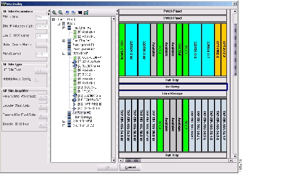
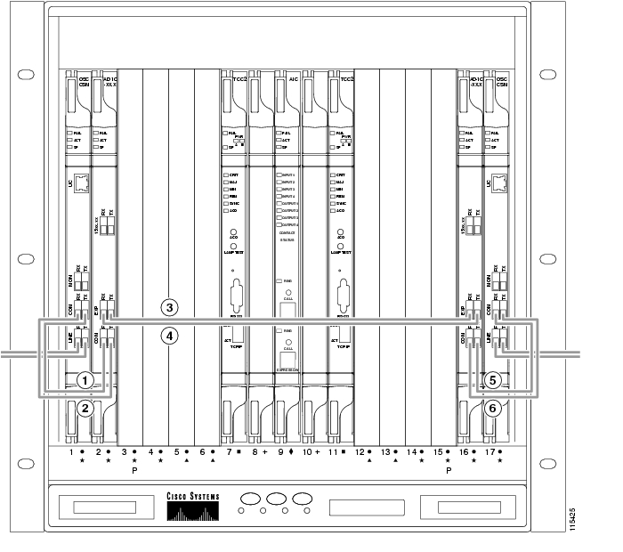
Cisco MetroPlanner provides a shelf layout ( Figure 3-1) showing the cards that should be installed in each ONS 15454 slot. Cisco MetroPlanner can export this as a table, "Layout Table [site name]," or as a JPG file with a user-defined name.
Installation Parameters
Table
Provides the target reference values for the variable optical attenuators (VOAs), output power, optical thresholds, and amplifier configuration parameters.
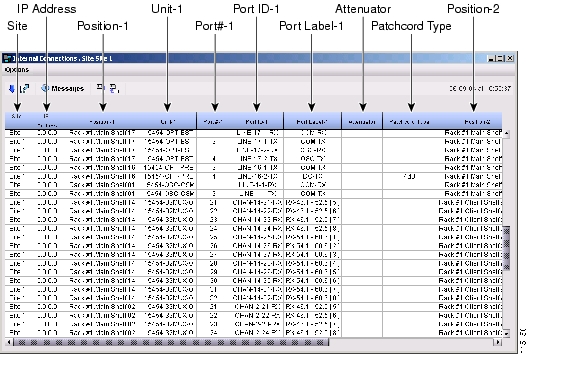
Internal Connections
Table
Identifies the patchcords that must be installed within the shelf.
Assisted Configuration Setup
TXT file
This is an electronic file with a TXT extension and a name corresponding to the node you are setting up. The file is imported into CTC where it configures the node parameters based on the network calculated by Cisco MetroPlanner.
Traffic Matrix
Table
Shows the traffic flow within the node. During node turn-up, this report is used to identify the location of Y-cable protection groups.
Cable list
Table or list
A list of cables needed to provision the node. The list can be derived from the Internal Connections table or from the Bill of Materials report prepared by Cisco MetroPlanner.
Figure 3-1 Cisco MetroPlanner Shelf Layout
If you not do not have all the reports and files listed in Table 3-1, do not continue. See your site or network planner for the required information and files.
Step 2
Stop. You have completed this procedure.
NTP-G22 Verify Common Card Installation
Step 1
Step 2
Note
Step 3
Step 4
•
•
Stop. You have completed this procedure.
NTP-G23 Create Users and Assign Security
Step 1
Note
Step 2
Note
Step 3
Stop. You have completed this procedure.
DLP-G54 Create a New User on a Single Node
Purpose
This task creates a new user for one ONS 15454.
Tools/Equipment
None
Prerequisite Procedures
Required/As Needed
As needed
Onsite/Remote
Onsite or remote
Security Level
Superuser
Step 1
Step 2
Step 3
•
•
Note
•
•
Note
Step 4
Step 5
DLP-G55 Create a New User on Multiple Nodes
Purpose
This task adds a new user to multiple ONS 15454 nodes.
Tools/Equipment
None
Prerequisite Procedures
Required/As Needed
As needed
Onsite/Remote
Onsite or remote
Security Level
Superuser
Note
Step 1
Step 2
Step 3
Step 4
•
•
•
•
Note
Step 5
Step 6
Step 7
Step 8
NTP-G24 Set Up Name, Date, Time, and Contact Information
Step 1
Step 2
Step 3
•
Note
•
•
•
CTC uses the latitude and longitude to position ONS 15454 icons on the network view map. To convert a coordinate in degrees to degrees and minutes, multiply the number after the decimal by 60. For example, the latitude 38.250739 converts to 38 degrees, 15 minutes (0.250739 x 60 = 15.0443, rounded to the nearest whole number).
•
•
If you do not use an SNTP or NTP server, complete the Date and Time fields. The ONS 15454 will use these fields for alarm dates and times. By default, CTC displays all alarms in the CTC computer time zone for consistency. To change the display to the node time zone, complete the "DLP-G118 Display Alarms and Conditions Using Time Zone" task.
Note
If you check the Use NTP/SNTP Server check box, type the IP address of one of the following:
–
–
If you check gateway network element (GNE) for the ONS 15454 SOCKS proxy server (see "DLP-G56 Provision IP Settings" task), external ONS 15454 nodes must reference the gateway ONS 15454 for NTP/SNTP timing. For more information about the ONS 15454 gateway settings, see "Management Connectivity Reference."
Caution
•
•
•
•
•
•
Step 4
Step 5
Step 6
Stop. You have completed this procedure.
NTP-G25 Set Power Monitor Thresholds
Purpose
This procedure provisions extreme high, extreme low, and low input battery power thresholds within a -48 VDC environment. When the thresholds are crossed, the TCC2/TCC2P generates warning alarms in CTC. For ONS 15454 power specifications, see Appendix B, "Hardware Specifications."
Tools/Equipment
None
Prerequisite Procedures
Required/As Needed
Required
Onsite/Remote
Onsite or remote
Security Level
Provisioning or higher
Caution
Step 1
Step 2
Step 3
Step 4
Step 5
Step 6
Step 7
Stop. You have completed this procedure.
NTP-G26 Set Up CTC Network Access
Step 1
Step 2
Tip
Step 3
Note
Step 4
Step 5
Step 6
Stop. You have completed this procedure.
DLP-G56 Provision IP Settings
Caution
Step 1
Step 2
•
•
•
–
–
–
•
–
–
–
•
Note
•
•
•
•
•
–
–
–
Step 3
Step 4
Both TCC2/TCC2P cards reboot, one at a time. During this time (approximately 5 minutes), the active and standby TCC2/TCC2P card LEDs go through the cycle shown in Table 3-2. Eventually, a "Lost node connection, switching to network view" message appears.
Step 5
Step 6
Step 7
DLP-G57 Set the IP Address, Default Router, and Network Mask Using the LCD
Note
Note
Step 1
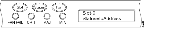
Step 2
•
•
•
Figure 3-2 Selecting the IP Address Option
Step 3
Figure 3-3 Changing the IP Address
Step 4
Tip
Step 5
Step 6
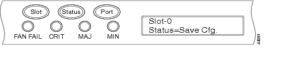
Step 7
Figure 3-4 Selecting the Save Configuration Option
Step 8
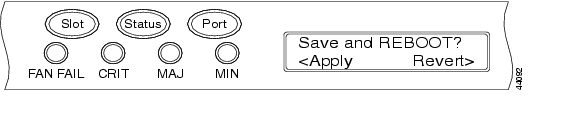
A Save and REBOOT message appears ( Figure 3-5).
Figure 3-5 Saving and Rebooting the TCC2/TCC2P
Step 9
Saving the new configuration causes the TCC2/TCC2P cards to reboot. During the reboot, a "Saving Changes - TCC Reset" message displays on the LCD. The LCD returns to the normal alternating display after the TCC2/TCC2P reboot is complete.
Note
Step 10
DLP-G264 Enable Node Security Mode
Purpose
This task enables the ONS 15454 security mode. When security mode is enabled, two IP addresses are assigned to the node. One address is assigned to the backplane LAN port and the other to the TCC2P RJ-45 TCP/IP (LAN) port.
Tools/Equipment
TCC2P cards must be installed.
Prerequisite Procedures
NTP-G103 Back Up the Database, page 13-2
Required/As Needed
As needed
Onsite/Remote
Onsite or remote
Security Level
Superuser
Note
Caution
Note
Step 1
Step 2
Step 3
Step 4
Step 5
Step 6
Step 7
Step 8
•
•
Note
Step 9
Within the next 30 to 40 seconds, the TCC2Ps reboot. CTC switches to network view, and the CTC Alerts dialog box appears. In network view, the node changes to grey and a DISCONNECTED condition appears.
Step 10
Step 11
a.
b.
c.
d.
e.
Note
Step 12
DLP-G58 Create a Static Route
Step 1
Step 2
Step 3
•
•
•
•
Step 4
Note
Step 5
DLP-G59 Set Up or Change Open Shortest Path First Protocol
Step 1
Step 2
•
•
•
Step 3
•
•
Step 4
a.
b.
•
•
•
c.
The authentication button label changes to Simple Password.
Step 5
The OSPF priority and interval defaults are the defaults most commonly used by OSPF routers. Verify that these defaults match the ones used by the OSPF router where the ONS 15454 is connected.
•
•
•
•
•
•
Step 6
Note
a.
b.
•
•
•
•
c.
Step 7
a.
b.
•
•
•
•
•
•
c.
Step 8
If you changed the Area ID, the TCC2/TCC2P cards reset, one at a time. The reset takes approximately 10 to 15 minutes. Table 3-2 shows the LED behavior during the TCC2/TCC2P reset.
Step 9
DLP-G60 Set Up or Change Routing Information Protocol
Step 1
Step 2
Step 3
Step 4
Step 5
a.
b.
•
•
•
c.
The authentication button label changes to Simple Password.
Step 6
a.
b.
•
•
•
c.
Step 7
NTP-G27 Set Up the ONS 15454 for Firewall Access
Step 1
Step 2
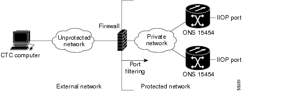
Figure 3-6 shows ONS 15454 nodes in a protected network and the CTC computer in an external network. For the computer to access the ONS 15454 nodes, you must provision the IIOP listener port specified by your firewall administrator on the ONS 15454.
Figure 3-6 Nodes Behind a Firewall
Step 3
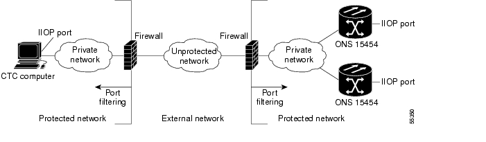
Figure 3-7 shows a CTC computer and ONS 15454 behind firewalls. For the computer to access the ONS 15454, you must provision the IIOP port on the CTC computer and on the ONS 15454.
Figure 3-7 CTC Computer and ONS 15454 Nodes Residing Behind Firewalls
Stop. You have completed this procedure.
DLP-G61 Provision the IIOP Listener Port on the ONS 15454
Note
Step 1
Step 2
•
•
•
Step 3
Step 4
Both ONS 15454 TCC2/TCC2P cards reboot, one at a time. The reboot takes approximately 15 minutes.
Step 5
DLP-G62 Provision the IIOP Listener Port on the CTC Computer
Purpose
This task selects the IIOP listener port on CTC and must be completed if the computer running CTC resides behind a firewall.
Tools/Equipment
IIOP listener port number from LAN or firewall administrator.
Prerequisite Procedures
G22 Verify Common Card Installation
Required/As Needed
As needed.
Onsite/Remote
Onsite or remote
Security Level
Provisioning or higher
Step 1
Step 2
Step 3
•
•
•
Step 4
Step 5
Step 6
Step 7
Step 8
NTP-G132 Provision OSI
Caution
Caution
Note
Step 1
Step 2
•
•
•
•
•
•
•
•
Stop. You have completed this procedure.
DLP-G283 Provision OSI Routing Mode
Purpose
This task provisions the OSI routing mode. Complete this task when the ONS 15454 is connected to networks with third party NEs that use the OSI protocol stack for DCN communication.
Tools/Equipment
None
Prerequisite Procedures
NTP-G15 Install the Common Control Cards, page 1-71
Required/As Needed
As needed
Onsite/Remote
Onsite
Security Level
Provisioning or higher
Caution
Caution
Caution
Note
Step 1
Step 2
•
Note
•
•
–
–
Step 3
•
•
Step 4
DLP-G284 Provision the TARP Operating Parameters
Step 1
Step 2
•
Note
•
Note
•
–
–
–
Note
•
Note
•
Note
•
Note
•
•
•
Note
•
•
•
•
•
•
Note
Step 3
Step 4
DLP-G285 Add a Static TID to NSAP Entry to the TARP Data Cache
Step 1
Step 2
Step 3
•
•
Step 4
Step 5
DLP-G287 Add a TARP Manual Adjacency Table Entry
Step 1
Step 2
Step 3
•
–
–
•
Step 4
Step 5
DLP-G288 Provision OSI Routers
Purpose
This task enables an OSI router and edits its primary manual area address.
Tools/Equipment
None
Prerequisite Procedures
G22 Verify Common Card Installation
Required/As Needed
As needed
Onsite/Remote
Onsite or remote
Security Level
Provisioning or higher
Note
Note
Note
Step 1
Step 2
Step 3
a.
b.
c.
d.
Step 4
DLP-G289 Provision Additional Manual Area Addresses
Purpose
This task provisions the OSI manual area addresses. One primary area and two additional manual areas can be created for each virtual router.
Tools/Equipment
None
Prerequisite Procedures
G22 Verify Common Card Installation
Required/As Needed
As needed
Onsite/Remote
Onsite or remote
Security Level
Provisioning or higher
Step 1
Step 2
Step 3
a.
b.
c.
d.
Step 4
DLP-G290 Enable the OSI Subnet on the LAN Interface
Purpose
This task enables the OSI subnetwork point of attachment on the LAN interface.
Tools/Equipment
None
Prerequisite Procedures
G22 Verify Common Card Installation
Required/As Needed
As needed
Onsite/Remote
Onsite or remote
Security Level
Provisioning or higher
Note
Note
Note
Step 1
Step 2
Step 3
•
•
•
•
•
Step 4
Step 5
DLP-G291 Create an IP-Over-CLNS Tunnel
Purpose
This task creates an IP-over-Connectionless Network Service (CLNS) tunnel to allow ONS 15454 nodes to communicate across equipment and networks that use the OSI protocol stack.
Tools/Equipment
None
Prerequisite Procedures
G22 Verify Common Card Installation
Required/As Needed
As needed
Onsite/Remote
Onsite or remote
Security Level
Provisioning or higher
Caution
Step 1
Step 2
Step 3
•
–
–
The Cisco proprietary tunnel is slightly more efficient than the GRE tunnel because it does not add the GRE header to each IP packet. The two tunnel types are not compatible. Most Cisco routers support the Cisco IP tunnel, while only a few support both GRE and Cisco IP tunnels. You generally should create Cisco IP tunnels if you are tunneling between two Cisco routers or between a Cisco router and an ONS node.
Caution
•
•
•
•
Step 4
Step 5
Step 6
NTP-G28 Set Up SNMP
Step 1
Step 2
Step 3
Step 4
•
•
Note
•
•
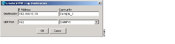
Figure 3-8 Creating an SNMP Trap
Step 5
Step 6
Step 7
Step 8
Note
For more information about the SNMP proxy feature, refer to the Cisco ONS 15454 Troubleshooting Guide or the Cisco ONS 15454 SDH Troubleshooting Guide.
Step 9
Step 10
a.
b.
Note
Note
Step 11
Stop. You have completed this procedure.
NTP-G29 Preprovision a Slot
Purpose
This procedure preprovisions the ONS 15454 slots in CTC based upon the Cisco MetroPlanner shelf layout prepared for your site. Preprovisioning the slots ensures that the physical cards are installed in the slots anticipated by the parameters contained in the Cisco MetroPlanner Assisted Configuration Setup that will be imported into CTC.
Tools/Equipment
Cisco MetroPlanner shelf layout or JPG file.
Prerequisite Procedures
"Connect the PC and Log into the GUI"
Required/As Needed
As needed
Onsite/Remote
Onsite or remote
Security Level
Provisioning or higher
Step 1
Step 2
Step 3
Note
Step 4
Stop. You have completed this procedure.
NTP-G30 Install the DWDM Cards
Purpose
This procedure describes how to install DWDM cards (OPT-PRE, OPT-BST, 32MUX-O, 32DMX-O, 32DMX, 32WSS, 4MD-xx.x, AD-1C-xx.x, AD-2C-xx.x, AD-4C-xx.x, AD-1B-xx.x, AD-4B-xx.x, OSCM, and OSC-CSM).
Tools/Equipment
•
•
•
Prerequisite Procedures
NTP-G15 Install the Common Control Cards, page 1-71
NTP-G14 Install DWDM Equipment, page 1-66
Required/As Needed
As needed
Onsite/Remote
Onsite
Security Level
Provisioning or higher
Warning
Warning
Warning
Caution
Note
Note
Note
Step 1
Caution
Step 2
Step 3
Step 4
Step 5
Step 6
Note
The following LED activity will occur:
•
•
•
•
•
•
Step 7
•
•
•
•
Note
Step 8
Step 9
•
•
Stop. You have completed this procedure.
NTP-G31 Install the DWDM Dispersion Compensating Units
Purpose
This procedure describes how to install the dispersion compensating units (DCU-xx.x) for DWDM shelves.
Tools/Equipment
DCU-xx.x cards
Prerequisite Procedures
NTP-G15 Install the Common Control Cards, page 1-71
NTP-G14 Install DWDM Equipment, page 1-66
Required/As Needed
As needed
Onsite/Remote
Onsite
Security Level
Provisioning or higher
Warning
Warning
Caution
Note
Note
Step 1
Step 2
Note
Note
Step 3
Note
Step 4
Stop. You have completed this procedure.
NTP-G32 Install the Transponder and Muxponder Cards
Purpose
This procedure describes how to install the ONS 15454 TXP and MXP cards.
Tools/Equipment
TXP_MR_10G, TXP_MR_10E, TXP_MR_2.5G, TXPP_MR_2.5G, MXP_2.5G_10G, MXP_2.5G_10E, MXP_MR_2.5G, and MXPP_MR_2.5G cards (as applicable)
Prerequisite Procedures
NTP-G15 Install the Common Control Cards, page 1-71
NTP-G14 Install DWDM Equipment, page 1-66
Required/As Needed
As needed
Onsite/Remote
Onsite
Security Level
None
Warning
Warning
Warning
Caution
Note
Note
Note
Step 1
Step 2
Step 3
Step 4
Note
Step 5
Note
The following LED activity will occur:
•
•
•
•
Note
Step 6
•
•
•
•
Step 7
•
•
Note
Step 8
Note
Note
Stop. You have completed this procedure.
DLP-G63 Install an SFP or XFP
Purpose
This task installs SFP/XFPs into TXP and MXP cards. SFP/XFPs provide a fiber interface to the card.
Tools/Equipment
None
Prerequisite Procedures
G32 Install the Transponder and Muxponder Cards
Required/As Needed
As needed
Onsite/Remote
Onsite
Security Level
Provisioning or higher
Note
Step 1
Step 2
•
•
•
Note
Step 3
Step 4
DLP-G273 Preprovision an SFP or XFP Slot
Step 1
Step 2
Step 3
Step 4
•
•
Step 5
Step 6
Step 7
Step 8
Step 9
DLP-G64 Remove an SFP or XFP
Purpose
This task removes SFP/XFPs from TXP and MXP cards.
Tools/Equipment
None
Prerequisite Procedures
Required/As Needed
As needed
Onsite/Remote
Onsite
Security Level
Provisioning or higher
Note
Step 1
Step 2
•
•
•
Step 3
Step 4
NTP-G123 Install the Filler Cards
Purpose
This procedure explains how to install the filler cards (blank faceplates) in any unused traffic or AIC-I card slots (Slots 1 through 6, 9, and 11 through 17). The filler card aids in maintaining proper air flow and EMI requirements and is detected by CTC in Software Release 6.0 and higher.
Tools/Equipment
Filler cards (Cisco P/N 15454-FILLER)
Prerequisite Procedures
G31 Install the DWDM Dispersion Compensating Units
Required/As Needed
As needed
Onsite/Remote
Onsite
Security Level
None
Warning
Caution
Step 1
Step 2
Step 3
Step 4
Stop. You have completed this procedure.
NTP-G34 Install Fiber-Optic Cables on DWDM Cards and DCUs
Purpose
This procedure installs the fiber-optic cables to DWDM cards and dispersion compensating units.
Tools/Equipment
Fiber-optic cables
Cisco MetroPlanner Internal Connections table
Prerequisite Procedures
G31 Install the DWDM Dispersion Compensating Units (as applicable)
Required/As Needed
As needed
Onsite/Remote
Onsite
Security Level
None
Warning
Note
Note
Step 1
Figure 3-9 Cisco MetroPlanner Internal Connections Table
Step 2
•
•
•
•
•
•
•
•
•
•
•
•
•
•
•
Caution
Step 3
Step 4
Step 5
Step 6
Step 7
Step 8
Step 9
•
•
•
•
•
•
Step 10
Stop. You have completed this procedure.
DLP-G65 Install Fiber-Optic Cables for OSC Link Terminations Between Two Adjacent Nodes
Purpose
This task explains how to install fiber-optic cables for optical to enable the optical service channel (OSC) link termination between two adjacent DWDM nodes.
Tools
Fiber-optic cables
Cisco MetroPlanner Internal Connections table
Prerequisite Procedures
NTP-G115 Clean Fiber Connectors, page 13-25
Required/As Needed
As needed
Onsite/Remote
Onsite
Security Level
None
Note
Note
Step 1
•
•
•
•
•
•
•
•
Figure 3-10 shows an example of OSC fibering for a hub node with OSCM cards installed.
Note
Figure 3-10 Fibering OSC Terminations—Hub Node with OSCM Cards
Step 2
Step 3
Step 4
Caution
Step 5
Note
Step 6
a.
b.
c.
d.
Step 7
Step 8
DLP-G66 Install Fiber-Optic Cables for a Hub Node
Purpose
This task installs fiber-optic cables on a hub node DWDM shelf.
Tools
Fiber-optic cables
Prerequisite Procedures
NTP-G115 Clean Fiber Connectors, page 13-25
Required/As Needed
As needed
Onsite/Remote
Onsite
Security Level
None
Note
Step 1
•
•
•
•
•
•
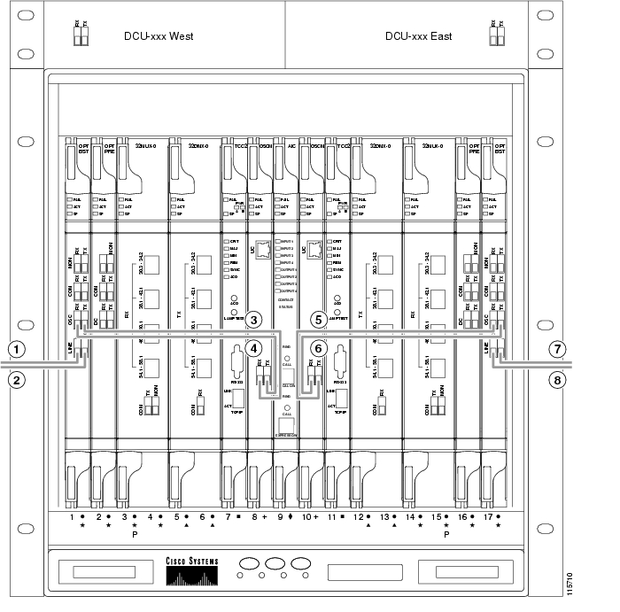
Figure 3-11 shows an example of a hub node with cabling. In the example, OSCM cards are installed. If OSC-CSM are installed, they are usually installed in Slots 1 and 17.
Note
Figure 3-11 Fibering a Hub Node
West DCU TX to west OPT-PRE DC RX1
East 32DMX-O COM RX to east OPT-PRE COM TX
West DCU RX to west OPT-PRE DC TX1
East 32MUX-O COM TX to east OPT-BST COM RX
West OPT-BST COM TX to west OPT-PRE COM RX
East OPT-PRE COM RX to east OPT-BST COM TX
West OPT-BST COM RX to west 32MUX-O COM TX
East DCU TX to east OPT-PRE DC RX1
West OPT-PRE COM TX to west 32DMX-O COM RX
East DCU RX to east OPT-PRE DC TX1
1 If a DCU is not installed, a 4-dB attenuator loop, +/- 1 dB must be installed between the OPT-PRE DC ports.
Step 2
Step 3
Step 4
Step 5
Caution
Step 6
Step 7
Note
Step 8
Step 9
DLP-G67 Install Fiber-Optic Cables for a Terminal Node
Purpose
This task installs fiber-optic cables on a terminal node DWDM shelf.
Tools
Fiber-optic cables
Prerequisite Procedures
NTP-G115 Clean Fiber Connectors, page 13-25
Required/As Needed
As needed
Onsite/Remote
Onsite
Security Level
None
Note
Step 1
•
•
•
•
Step 2
Step 3
Step 4
Step 5
Caution
Step 6
Step 7
Note
Step 8
Step 9
DLP-G68 Install Fiber-Optic Cables for a Line Amplifier Node
Purpose
This task installs fiber-optic cables on a line amplifier node in a DWDM shelf.
Tools
Fiber-optic cables
Prerequisite Procedures
NTP-G115 Clean Fiber Connectors, page 13-25
Required/As Needed
As needed
Onsite/Remote
Onsite
Security Level
None
Note
Step 1
•
–
–
–
–
•
–
–
•
•
–
–
•
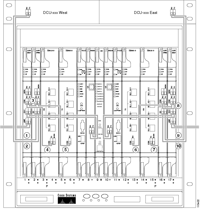
Figure 3-12 shows an example of a line amplifier node with cabling.
Note
Figure 3-12 Fibering a Line Amplifier Node
West DCU TX to west OPT-PRE DC RX1
West OPT-BST COM RX to east OPT-PRE COM TX
West DCU RX to west OPT-PRE DC TX1
West OPT-BST COM RX to east OPT-PRE COM TX
West OPT-BST COM TX to west OPT-PRE COM RX
East DCU TX to east OPT-PRE DC RX1
West OPT-PRE COM TX to east OPT-BST COM RX
East DCU RX to east OPT-PRE DC TX1
1 If a DCU is not installed, a 4-dB attenuator loop, +/- 1dB must be installed between the OPT-PRE DC ports.
Step 2
Step 3
Step 4
Step 5
Caution
Step 6
Step 7
Note
Step 8
Step 9
DLP-G69 Install Fiber-Optic Cables for an OSC Regeneration Node
Purpose
This task installs fiber-optic cables on an OSC regeneration node in a DWDM shelf.
Tools
Fiber-optic cables
Prerequisite Procedures
NTP-G115 Clean Fiber Connectors, page 13-25
Required/As Needed
As needed
Onsite/Remote
Onsite
Security Level
None
Note
Step 1
•
•
•
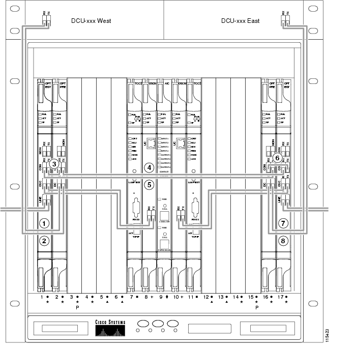
Figure 3-13 shows an example of an OSC regeneration node with cabling.
Note
Figure 3-13 Fibering an OSC Regeneration Node
Step 2
Step 3
Step 4
Step 5
Caution
Step 6
Step 7
Note
Step 8
Step 9
DLP-G70 Install Fiber-Optic Cables for an Amplified or Passive OADM Node
Purpose
This task gives instructions, rules, and examples for installing fiber-optic cables on an amplified or passive optical add/drop multiplexing (OADM) node in a DWDM shelf.
Tools
Fiber-optic cables
Prerequisite Procedures
NTP-G115 Clean Fiber Connectors, page 13-25
Required/As Needed
As needed
Onsite/Remote
Onsite
Security Level
None
Note
Note
Step 1
•
–
–
–
–
Step 2
•
•
•
•
•
•
•
•
•
•
•
•
•
Step 3
•
–
–
•
•
•
Step 4
•
•
•
•
•
•
•
•
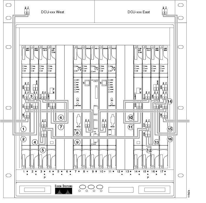
Figure 3-14 shows an example of an amplified OADM node with AD-1C-xx.x cards installed.
Note
Figure 3-14 Fibering an Amplified OADM Node
West DCU TX to west OPT-PRE DC RX1
West AD-1C-xx.x EXP RX to east AD-1C-xx.x EXP TX
West DCU RX to west OPT-PRE DC TX1
East TXP_MR_2.5G DWDM RX to east AD-1C-xx.x (15xx.xx) TX
West OPT-BST COM TX to west OPT-PRE COM RX
East TXP_MR_2.5G DWDM TX to east AD-1C-xx.x (15xx.xx) RX
West OPT-BST COM RX to west AD-1C-xx.x COM TX
East AD-1C-xx.x COM RX to OPT-PRE COM TX
West OPT-PRE COM TX to west AD-1C-xx.x COM RX
East AD-1C-xx.x COM TX to OPT-BST COM RX
West AD-1C-xx.x (15xx.xx) RX to west TXP_MR_2.5G DWDM TX
East OPT-PRE COM RX to east OPT-BST COM TX
West AD-1C-xx.x (15xx.xx) TX to west TXP_MR_2.5G DWDM RX
East DCU TX to east OPT-PRE DC RX1
West AD-1C-xx.x EXP TX to east AD-1C-xx.x EXP RX
East DCU RX to east OPT-PRE DC TX1
1 If a DCU is not installed, a 4-dB attenuator loop, +/1 dB must be installed between the OPT-PRE DC ports.
Figure 3-15 shows an example of a passive OADM node with two AD-1C-xx.x cards installed.
Note
Figure 3-15 Fibering a Passive OADM Node
Step 5
Step 6
Step 7
Step 8
Caution
Step 9
Step 10
Note
Step 11
Step 12
DLP-G71 Install Fiber-Optic Cables for an ROADM Node
Purpose
This task gives instructions, rules, and examples for installing fiber-optic cables on an ROADM node in a DWDM shelf.
Tools
Fiber-optic cables
Prerequisite Procedures
NTP-G115 Clean Fiber Connectors, page 13-25
Required/As Needed
As needed
Onsite/Remote
Onsite
Security Level
None
Note
Note
Step 1
•
•
•
•
•
•
•
•
•
•
•
•
•
•
Figure 3-16 shows an example of an amplified ROADM node with cabling.
Note
Figure 3-16 Fibering an ROADM Node
West DCU TX to west OPT-PRE DC RX1
West 32WSS EXP RX to east 32WSS EXP TX
West DCU RX to west OPT-PRE DC TX1
East 32DMX COM RX to east 32WSS DROP TX
West OPT-BST COM TX to west OPT-PRE COM RX
East 32WSS COM RX to east OPT-PRE COM TX
West 32WSS COM TX to west OPT-BST COM RX
East 32WSS COM TX to east OPT-BST COM RX
West 32WSS COM RX to west OPT-PRE COM TX
East OPT-BST COM TX to east OPT-PRE COM RX
West 32DMX COM RX to west 32WSS DROP TX
East DCU RX to east OPT-PRE DC TX1
West 32WSS EXP TX to east 32WSS EXP RX
East DCU TX to east OPT-PRE DC RX1
1 If a DCU is not installed, a 4-dB attenuator loop, +/-1 dB must be installed between the OPT-PRE DC ports.
Step 2
Step 3
Step 4
Step 5
Caution
Step 6
Step 7
Note
Step 8
Step 9
NTP-G140 Install Fiber-Optic Cables Between a Terminal, Hub, or ROADM Node and the Transponder Cards
Purpose
This procedure routes fiber-optic cables from 32MUX-O, 32WSS, 32DMX-O, and 32DMX cards in a terminal, hub, or ROADM node to the patch panel, and from the patch panel to TXP/MXP cards.
Tools/Equipment
The following node types require the following equipment. The cards and patch panels should already be installed before you begin this procedure.
Terminal node:
•
•
•
•
Hub node:
•
•
•
•
ROADM node:
•
•
•
•
Fiber-optic cables, terminated with a single LC-type connector on each end
Prerequisite Procedures
DLP-G28 Install the Fiber Patch-Panel Tray, page 1-67
DLP-G29 Install the Fiber-Storage Tray, page 1-68
Required/As Needed
As needed
Onsite/Remote
Onsite
Security Level
None
Step 1
Step 2
•
•
Step 3
Stop. You have completed this procedure.
DLP-G315 Install Fiber-Optic Cables From the 32WSS/32DMX and 32MUX-O/32DMX-O Cards to the Patch Panel
Note
Step 4
Step 5
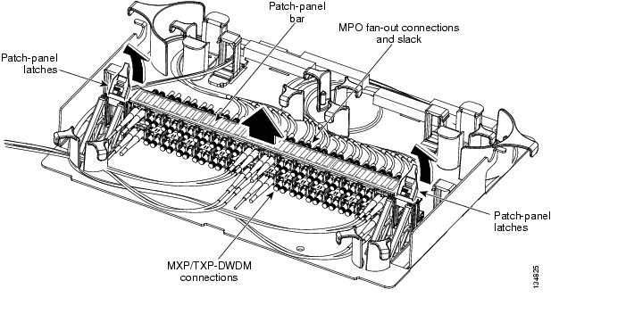
Figure 3-17 Using the Patch-Panel Latches to Slide the Patch Panel Away from the Tray
Step 6
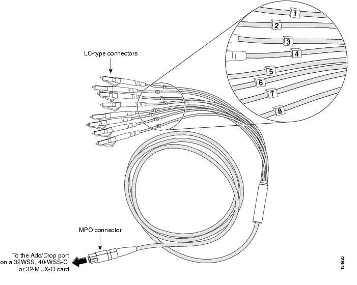
Figure 3-18 MPO Cable
.
Step 7
Caution
Step 8
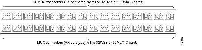
Figure 3-19 shows the patch-panel connectors from the rear of the patch-panel tray. Figure 3-20 shows the assigned wavelengths for each port on the patch panel, as indicated at the top of the patch-panel bar. The numbers on the patch-panel bar correspond to a wavelength on the ITU grid.
Figure 3-19 Rear View of the Patch Panel
.
Figure 3-20 Top View of the Patch-Panel Bar
Step 9
Step 10
Step 11
Caution
Step 12
Step 13
Step 14
Step 15
DLP-G316 Install Fiber-Optic Cables from a TXP/MXP Node to the Patch Panel
Step 1
Step 2
Caution
Step 3
Figure 3-21 shows the patch-panel connectors from the front of the patch-panel tray.
Figure 3-21 Front View of the Patch Panel
.
Step 4
Step 5
Step 6
Step 7
NTP-G141 Install Fiber-Optic Cables for Y-Cable Protection Modules
Purpose
This procedure installs and routes fiber-optic cables from the client signal to the Y-cable protection module (single mode or multimode), and from the Y-cable module to the transponder node. Using one Y-cable protection module, you can protect one client signal with two TXP/MXP cards, and two client signals with four TXP/MXP cards.
Tools/Equipment
Fiber-optic cables
Prerequisite Procedures
DLP-G32 Install the Y-Cable Protection Modules, page 1-70
Required/As Needed
As needed
Onsite/Remote
Onsite
Security Level
None
Note
Step 1
Caution
To protect one client signal, connect the fiber-optic cables according to either Table 3-4 or Table 3-5. To protect two client signals using a single Y-cable module, connect the cables according to both Table 3-4 and Table 3-5.
Stop. You have completed this procedure.
NTP-G36 Calculate Cable Connections
Purpose
This procedure verifies the cards that are installed in the shelf and calculates the connections that should be provisioned for them.
Tools/Equipment
Cisco MetroPlanner shelf layout
Cisco MetroPlanner Internal Connections table
Prerequisite Procedures
G22 Verify Common Card Installation
Required/As Needed
Required
Onsite/Remote
Onsite or remote
Security Level
Superuser
Step 1
Step 2
Step 3
CTC verifies that the cards installed in the ONS 15454 shelf are compatible and will operate together as a valid DWDM node configuration. Furthermore, based on the cards installed or preprovisioned, CTC calculates the intra-shelf patchcords that are expected to be installed. If the cards are not compatible or are missing, for example, if an OPT-BST is installed but an OSCM card is not installed, the calculate connections function generates an error.
Note
Step 4
Step 5
Step 6
Note
Stop. You have completed this procedure.
DLP-G72 Create a DWDM Connection
Step 1
Step 2
Step 3
Step 4
Step 5
Step 6
Step 7
Step 8
DLP-G73 Delete a DWDM Connection
Purpose
This task deletes a DWDM connection.
Tools/Equipment
None
Prerequisite Procedures
Required/As Needed
Required
Onsite/Remote
Onsite or remote
Security Level
Superuser
Step 1
Step 2
Step 3
Step 4
NTP-G138 Import a Cisco MetroPlanner Configuration File
Caution
Step 1
Step 2
Step 3
Step 4
Step 5
Step 6
The Import NE Update From File dialog box closes, and the MetroPlanner configuration settings are imported.
Step 7
Stop. You have completed this procedure.
NTP-G37 Run Automatic Node Setup
Purpose
This procedure runs the CTC DWDM ANS function. ANS adjusts the values of the variable optical attenuators (VOAs) to equalize the per-channel power at the amplifier level.
Tools/Equipment
The Cisco MetroPlanner Installation Parameters file
Prerequisite Procedures
G36 Calculate Cable Connections
G138 Import a Cisco MetroPlanner Configuration File
Required/As Needed
Required
Onsite/Remote
Onsite or remote
Security Level
Superuser
Step 1
Step 2
Step 3
Step 4
Step 5
Step 6
Step 7
Step 8
Step 9
Step 10
Step 11
•
•
•
If one of the following statuses is shown, complete the provided instructions:
•
Note
•
Stop. You have completed this procedure.
NTP-G38 Provision OSC Terminations
Purpose
This procedure provisions the OSC terminations.
Tools/Equipment
None
Prerequisite Procedures
Required/As Needed
Required
Onsite/Remote
Onsite or remote
Security Level
Superuser
Step 1
Step 2
Step 3
Figure 3-22 OSC Terminations Area
Step 4
Note
Step 5
•
•
Step 6
a.
b.
–
–
–
–
–
Step 7
•
•
•
Note
Stop. You have completed this procedure.
NTP-G39 Verify OSCM and OSC-CSM Transmit Power
Step 1
Step 2
Step 3
Step 4
Step 5
Step 6
•
•
Step 7
Step 8
Step 9
Step 10
Stop. You have completed this procedure.
DLP-G313 Verify OSC-CSM Transmit Power
Note
Step 1
Step 2
Step 3
Step 4
Step 5
For OSC-CSM cards installed on the east side:
a.
b.
c.
d.
For OSC-CSM cards installed on the west side:
a.
b.
c.
d.
Step 6
a.
b.
c.
d.
e.
Step 7
a.
b.
c.
d.
e.
f.
g.
h.
Step 8
a.
b.
c.
d.
e.
f.
Step 9
DLP-G314 Verify OSCM Transmit Power
Purpose
This procedure verifies the transmit power of the OSCM card.
Tools/Equipment
None
Prerequisite Procedures
Required/As Needed
Required
Onsite/Remote
Onsite or remote
Security Level
Superuser
Note
Step 1
Step 2
Step 3
Step 4
Step 5
For OSCM cards installed on the east side:
a.
b.
c.
d.
For OCSM cards installed on the west side:
a.
b.
c.
d.
Step 6
a.
b.
c.
–
–
–
d.
Step 7
![]()
![]()
![]()
![]()
![]()
![]()
![]()
![]()
Posted: Mon Dec 3 04:01:01 PST 2007
All contents are Copyright © 1992--2007 Cisco Systems, Inc. All rights reserved.
Important Notices and Privacy Statement.