|
|

Table Of Contents
Management Connectivity Reference
22.2.1 Scenario 1: CTC and ONS 15454s on Same Subnet
22.2.2 Scenario 2: CTC and ONS 15454s Connected to a Router
22.2.3 Scenario 3: Using Proxy ARP to Enable an ONS 15454 Gateway
22.2.4 Scenario 4: Default Gateway on CTC Computer
22.2.5 Scenario 5: Using Static Routes to Connect to LANs
22.2.7 Scenario 7: Provisioning the ONS 15454 Proxy Server
22.2.8 Scenario 8: Dual GNEs on a Subnet
22.2.9 Scenario 9: IP Addressing with Secure Mode Enabled
22.7 TCP/IP and OSI Networking
Management Connectivity Reference
This chapter provides nine scenarios showing Cisco ONS 15454s in common IP network configurations as well as information about provisionable patchcords, the routing table, external firewalls, and open gateway network element (GNE) networks. The chapter does not provide a comprehensive explanation of IP networking concepts and procedures. For IP setup instructions, see the "DLP-G56 Provision IP Settings" task on page 3-12.
Note
Unless otherwise specified, "ONS 15454" refers to both ANSI and ETSI shelf assemblies.
Chapter topics include:
•
Note
22.1 IP Networking Overview
ONS 15454s can be connected in many different ways within an IP environment:
•
•
•
•
•
•
22.2 IP Addressing Scenarios
ONS 15454 IP addressing generally has eight common scenarios or configurations. Use the scenarios as building blocks for more complex network configurations. Table 22-1 provides a general list of items to check when setting up ONS 15454s in IP networks.
22.2.1 Scenario 1: CTC and ONS 15454s on Same Subnet
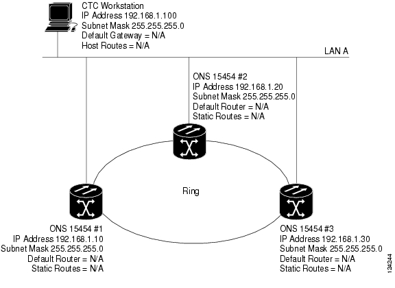
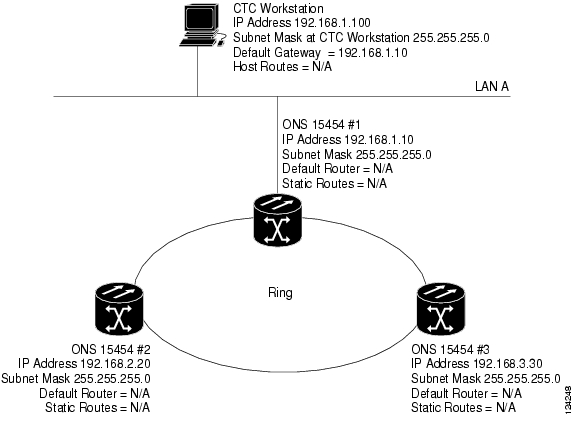
Scenario 1 shows a basic ONS 15454 LAN configuration ( Figure 22-1). The ONS 15454s and CTC computer reside on the same subnet. All ONS 15454s connect to LAN A, and all ONS 15454s have DCC connections.
Figure 22-1 Scenario 1: CTC and ONS 15454s on Same Subnet (ANSI and ETSI)
22.2.2 Scenario 2: CTC and ONS 15454s Connected to a Router
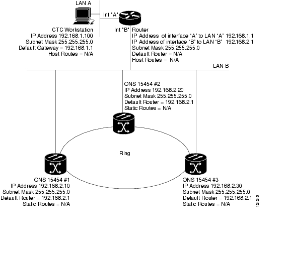
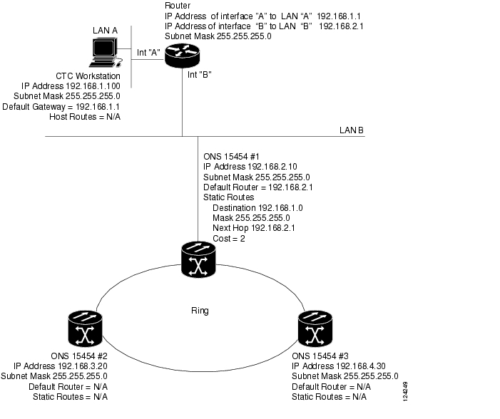
In Scenario 2, the CTC computer resides on a subnet (192.168.1.0) and attaches to LAN A ( Figure 22-2). The ONS 15454s reside on a different subnet (192.168.2.0) and attach to LAN B. A router connects LAN A to LAN B. The IP address of router interface A is set to LAN A (192.168.1.1), and the IP address of router interface B is set to LAN B (192.168.2.1). The routers each have a subnet mask of 255.255.255.0.
On the CTC computer, the default gateway is set to router interface A. If the LAN uses DHCP (Dynamic Host Configuration Protocol), the default gateway and IP address are assigned automatically. In the Figure 22-2 example, a DHCP server is not available.
Figure 22-2 Scenario 2: CTC and ONS 15454s Connected to Router (ANSI and ETSI)
22.2.3 Scenario 3: Using Proxy ARP to Enable an ONS 15454 Gateway
ARP matches higher-level IP addresses to the physical addresses of the destination host. It uses a lookup table (called ARP cache) to perform the translation. When the address is not found in the ARP cache, a broadcast is sent out on the network with a special format called the ARP request. If one of the machines on the network recognizes its own IP address in the request, it sends an ARP reply back to the requesting host. The reply contains the physical hardware address of the receiving host. The requesting host stores this address in its ARP cache so that all subsequent datagrams (packets) to this destination IP address can be translated to a physical address.
Proxy ARP enables one LAN-connected ONS 15454 to respond to the ARP request for ONS 15454s not connected to the LAN. (ONS 15454 proxy ARP requires no user configuration.) For this to occur, the DCC-connected ONS 15454s must reside on the same subnet as the LAN-connected (gateway) ONS 15454. When a LAN device sends an ARP request to an ONS 15454 that is not connected to the LAN, the gateway ONS 15454 (the one connected to the LAN) returns its MAC address to the LAN device. The LAN device then sends the datagram for the remote ONS 15454 to the MAC address of the proxy ONS 15454. The proxy ONS 15454 uses its routing table to forward the datagram to the non-LAN ONS 15454.
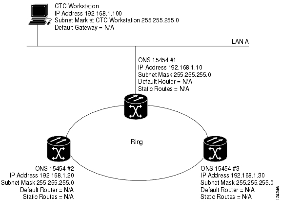
Scenario 3 is similar to Scenario 1, but only one ONS 15454 (Node 1) connects to the LAN ( Figure 22-3). Two ONS 15454s (Node 2 and Node 3) connect to ONS 15454 Node 1 through the section DCC. Because all three ONS 15454s are on the same subnet, proxy ARP enables ONS 15454 Node 1 to serve as a gateway for ONS 15345 Node 2 and Node 3.
Note
Be aware that:
•
•
•
•
Figure 22-3 Scenario 3: Using Proxy ARP (ANSI and ETSI)
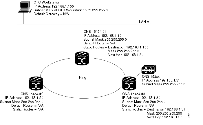
You can also use proxy ARP to communicate with hosts attached to the craft Ethernet ports of DCC-connected nodes ( Figure 22-4). The node with an attached host must have a static route to the host. Static routes are propagated to all DCC peers using OSPF. The existing proxy ARP node is the gateway for additional hosts. Each node examines its routing table for routes to hosts that are not connected to the DCC network but are within the subnet. The existing proxy server replies to ARP requests for these additional hosts with the node MAC address. The existence of the host route in the routing table ensures that the IP packets addressed to the additional hosts are routed properly. Other than establishing a static route between a node and an additional host, no provisioning is necessary. The following restrictions apply:
•
•
In Figure 22-4, Node 1 announces to Node 2 and 3 that it can reach the CTC host. Similarly, Node 3 announces that it can reach the ONS 152xx. The ONS 152xx is shown as an example; any network element can be set up as an additional host.
Figure 22-4 Scenario 3: Using Proxy ARP with Static Routing (ANSI and ETSI)
22.2.4 Scenario 4: Default Gateway on CTC Computer
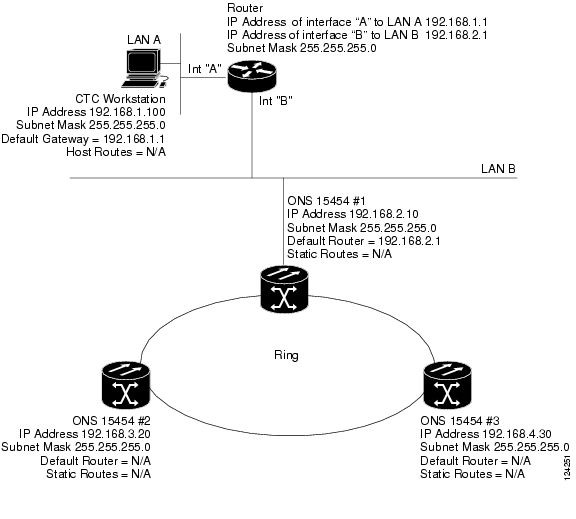
Scenario 4 is similar to Scenario 3, but Nodes 2 and 3 reside on different subnets, 192.168.2.0 and 192.168.3.0, respectively ( Figure 22-5). Node 1 and the CTC computer are on subnet 192.168.1.0. Proxy ARP is not used because the network includes different subnets. For the CTC computer to communicate with Nodes 2 and 3, Node 1 is entered as the default gateway on the CTC computer.
Figure 22-5 Scenario 4: Default Gateway on a CTC Computer (ANSI and ETSI)
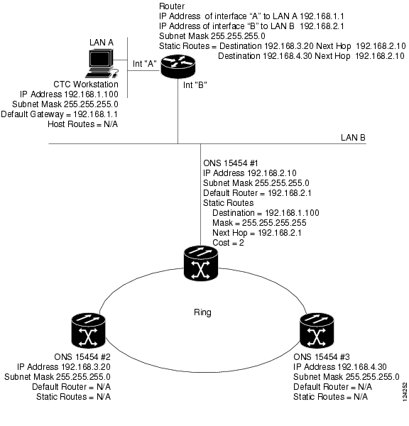
22.2.5 Scenario 5: Using Static Routes to Connect to LANs
Static routes are used for two purposes:
•
•
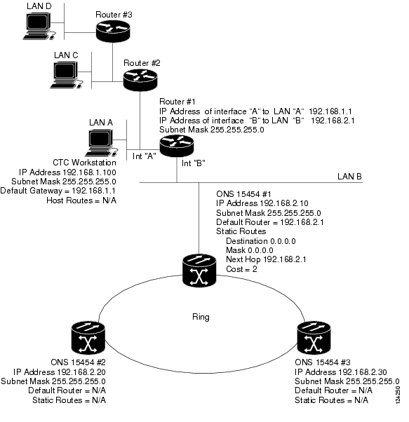
In Figure 22-6, one CTC residing on subnet 192.168.1.0 connects to a router through interface A (the router is not set up with OSPF). ONS 15454s residing on different subnets are connected through Node 1 to the router through interface B. Because Nodes 2 and 3 are on different subnets, proxy ARP does not enable Node 1 as a gateway. To connect to CTC computers on LAN A, a static route is created on
Node 1.Figure 22-6 Scenario 5: Static Route With One CTC Computer Used as a Destination (ANSI and ETSI)
The destination and subnet mask entries control access to the ONS 15454s:
•
•
•
The IP address of router interface B is entered as the next hop, and the cost (number of hops from source to destination) is 2.
Figure 22-7 Scenario 5: Static Route With Multiple LAN Destinations (ANSI and ETSI)
22.2.6 Scenario 6: Using OSPF
Open Shortest Path First (OSPF) is a link state Internet routing protocol. Link state protocols use a "hello protocol" to monitor their links with adjacent routers and to test the status of their links to their neighbors. Link state protocols advertise their directly connected networks and their active links. Each link state router captures the link state "advertisements" and puts them together to create a topology of the entire network or area. From this database, the router calculates a routing table by constructing a shortest path tree. Routes are recalculated when topology changes occur.
ONS 15454s use the OSPF protocol in internal ONS 15454 networks for node discovery, circuit routing, and node management. You can enable OSPF on the ONS 15454s so that the ONS 15454 topology is sent to OSPF routers on a LAN. Advertising the ONS 15454 network topology to LAN routers eliminates the need to manually enter static routes for ONS 15454 subnetworks. Figure 22-8 shows a network enabled for OSPF. Figure 22-9 shows the same network without OSPF. Static routes must be manually added to the router for CTC computers on LAN A to communicate with Nodes 2 and 3 because these nodes reside on different subnets.
OSPF divides networks into smaller regions, called areas. An area is a collection of networked end systems, routers, and transmission facilities organized by traffic patterns. Each OSPF area has a unique ID number, known as the area ID. Every OSPF network has one backbone area called "area 0." All other OSPF areas must connect to area 0.
When you enable an ONS 15454 OSPF topology for advertising to an OSPF network, you must assign an OSPF area ID in decimal format to the ONS 15454 network. An area ID is a "dotted quad" value that appears similar to an IP address. Coordinate the area ID number assignment with your LAN administrator. All DCC-connected ONS 15454s should be assigned the same OSPF area ID.
Note
Figure 22-8 Scenario 6: OSPF Enabled (ANSI and ETSI)
Figure 22-9 Scenario 6: OSPF Not Enabled (ANSI and ETSI)
22.2.7 Scenario 7: Provisioning the ONS 15454 Proxy Server
The ONS 15454 proxy server is a set of functions that allows you to network ONS 15454s in environments where visibility and accessibility between ONS 15454s and CTC computers must be restricted. For example, you can set up a network so that field technicians and network operating center (NOC) personnel can both access the same ONS 15454s while preventing the field technicians from accessing the NOC LAN. To do this, one ONS 15454 is provisioned as a GNE and the other ONS 15454s are provisioned as end network elements (ENEs). The GNE ONS 15454 tunnels connections between CTC computers and ENE ONS 15454s, providing management capability while preventing access for non-ONS 15454 management purposes.
The ONS 15454 gateway setting performs the following tasks:
•
•
•
The ONS 15454 proxy server is provisioned using the Enable proxy server on port check box on the Provisioning > Network > General tab. If checked, the ONS 15454 serves as a proxy for connections between CTC clients and ONS 15454s that are DCC-connected to the proxy ONS 15454. The CTC client establishes connections to DCC-connected nodes through the proxy node. The CTC client can connect to nodes that it cannot directly reach from the host on which it runs. If not selected, the node does not proxy for any CTC clients, although any established proxy connections continue until the CTC client exits. In addition, you can set the proxy server as an ENE or a GNE:
•
In addition, firewall is enabled, which means that the node prevents IP traffic from being routed between the DCC and the LAN port. The ONS 15454 can communicate with machines connected to the LAN port or connected through the DCC. However, the DCC-connected machines cannot communicate with the LAN-connected machines, and the LAN-connected machines cannot communicate with the DCC-connected machines. A CTC client using the LAN to connect to the firewall-enabled node can use the proxy capability to manage the DCC-connected nodes that would otherwise be unreachable. A CTC client connected to a DCC-connected node can only manage other DCC-connected nodes and the firewall itself.
•
•
Note
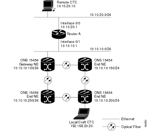
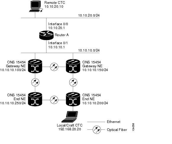
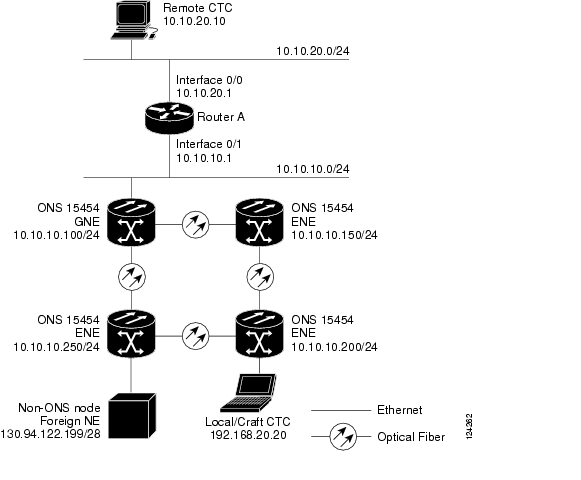
Figure 22-10 shows an ONS 15454 proxy server implementation. A GNE ONS 15454 is connected to a central office LAN and to ENE ONS 15454s. The central office LAN is connected to a NOC LAN, which has CTC computers. The NOC CTC computer and craft technicians must both be able to access the ONS 15454 ENEs. However, the craft technicians must be prevented from accessing or seeing the NOC or central office LANs.
In the example, the ONS 15454 GNE is assigned an IP address within the central office LAN and is physically connected to the LAN through its LAN port. ONS 15454 ENEs are assigned IP addresses that are outside the central office LAN and given private network IP addresses. If the ONS 15454 ENEs are collocated, the craft LAN ports could be connected to a hub. However, the hub should have no other network connections.
Figure 22-10 Scenario 7: ONS 15454 Proxy Server with GNE and ENEs on the Same Subnet (ANSI and ETSI)
Table 22-2 shows recommended settings for ONS 15454 GNEs and ENEs in the configuration shown in Figure 22-10.
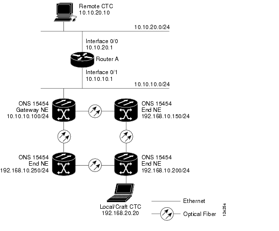
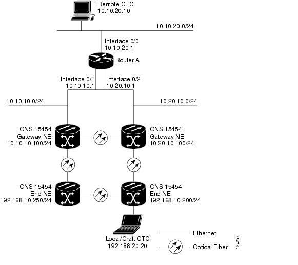
Figure 22-11 shows the same proxy server implementation with ONS 15454 ENEs on different subnets. The ONS 15454 GNEs and ENEs are provisioned with the settings shown in Table 22-2.
Figure 22-11 Scenario 7: ONS 15454 Proxy Server with GNE and ENEs on Different Subnets (ANSI and ETSI)
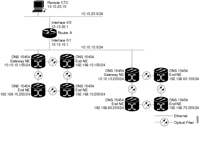
Figure 22-12 shows the same proxy server implementation with ONS 15454 ENEs in multiple rings.
Figure 22-12 Scenario 7: ONS 15454 Proxy Server With ENEs on Multiple Rings (ANSI and ETSI)
Table 22-3 shows the rules the ONS 15454 follows to filter packets for the firewall when nodes are configured as ENEs and GNEs. If the packet is addressed to the ONS 15454, additional rules (shown in Table 22-4) are applied. Rejected packets are silently discarded.
If you implement the proxy server, note that all DCC-connected ONS 15454s on the same Ethernet segment must have the same gateway setting. Mixed values produce unpredictable results, and might leave some nodes unreachable through the shared Ethernet segment.
If nodes become unreachable, correct the setting by performing one of the following:
•
•
22.2.8 Scenario 8: Dual GNEs on a Subnet
The ONS 15454 provides GNE load balancing, which allows CTC to reach ENEs over multiple GNEs without the ENEs being advertised over OSPF. This feature allows a network to quickly recover from the loss of GNE, even if the GNE is on a different subnet. If a GNE fails, all connections through that GNE fail. CTC disconnects from the failed GNE and from all ENEs for which the GNE was a proxy, and then reconnects through the remaining GNEs. GNE load balancing reduces the dependency on the launch GNE and DCC bandwidth, both of which enhance CTC performance.
Note
Figure 22-13 shows a network with dual GNEs on the same subnet.
Figure 22-13 Scenario 8: Dual GNEs on the Same Subnet (ANSI and ETSI)
Figure 22-14 shows a network with dual GNEs on different subnets.
Figure 22-14 Scenario 8: Dual GNEs on Different Subnets (ANSI and ETSI)
22.2.9 Scenario 9: IP Addressing with Secure Mode Enabled
TCC2P cards provide a secure mode option allowing you to provision two IP addresses for the ONS 15454. One IP address is provisioned for the ONS 15454 backplane LAN port. The other IP address is provisioned for the TCC2P TCP/IP craft port. The two IP addresses provide an additional layer of separation between the craft access port and the ONS 15454 LAN. If secure mode is enabled, the IP addresses provisioned for the TCC2P TCP/IP ports must follow general IP addressing guidelines. In addition, TCC2P IP addresses must reside on a different subnet from the ONS 15454 backplane port and ONS 15454 default router IP addresses.
The IP address assigned to the backplane LAN port becomes a private address, which is used to connect the ONS 15454 GNE to an OSS (Operations Support System) through a central office LAN or private enterprise network. In secure mode, the backplane's LAN IP address is not displayed on the CTC node view or to a technician directly connected to the node by default. This default can be changed to allow the backplane IP address to be viewed on CTC only by a Superuser.
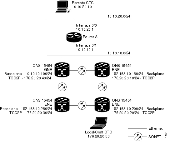
Figure 22-15 shows an example of ONS 15454s on the same subnet with secure mode enabled.
Note
Figure 22-15 Scenario 9: ONS 15454 GNE and ENEs on the Same Subnet with Secure Mode Enabled
Figure 22-16 shows an example of ONS 15454s connected to a router with secure mode enabled. In each example, TCC2P port addresses are on a different subnet from the node backplane addresses.
Figure 22-16 Scenario 9: ONS 15454 GNE and ENEs on Different Subnets with Secure Mode Enabled
22.3 Provisionable Patchcords
A provisionable patchcord is a user-provisioned link that is advertised by OSPF throughout the network. Provisionable patchcords, also called virtual links, are needed in the following situations:
•
•
•
•
Provisionable patchcords are required on both ends of a physical link. The provisioning at each end includes a local patchcord ID, slot/port information, remote IP address, and remote patchcord ID. Patchcords appear as dashed lines in CTC network view.
Table 22-5 lists the supported card combinations for client and trunk ports in a provisionable patchcord.
Note
Table 22-6 lists the supported card combinations for client-to-client ports in a patchcord.
Table 22-7 lists the supported card combinations for trunk-to-trunk ports in a patchcord.
Optical ports have the following requirements when used in a provisionable patchcord:
•
•
•
Transponder and muxponder ports have the following requirements when used in a provisionable patchcord:
•
•
•
DWDM cards support provisionable patchcords only on optical channel ports. Each DWDM optical channel port can have only one provisionable patchcord.
22.4 Routing Table
ONS 15454 routing information is displayed on the Maintenance > Routing Table tabs. The routing table provides the following information:
•
•
•
•
•
–
–
–
Table 22-8 shows sample routing entries for an ONS 15454.
Entry 1 shows the following:
•
•
•
•
Entry 2 shows the following:
•
•
•
•
Entry 3 shows the following:
•
•
•
•
Entry 4 shows the following:
•
•
•
•
Entry 5 shows a DCC-connected node that is accessible through a node that is not directly connected:
•
•
•
•
22.5 External Firewalls
This section provides sample access control lists for external firewalls. Table 22-9 lists the ports that are used by the TCC2/TCC2P.
Table 22-9 Ports Used by the TCC2/TCC2P
0
Never used
D
20
FTP
D
21
FTP control
D
22
SSH
D
23
Telnet
D
80
HTTP
D
111
SUNRPC
NA
161
SNMP traps destinations
D
162
SNMP traps destinations
D
513
rlogin
D
683
CORBA IIOP
OK
1080
Proxy server (socks)
D
2001-2017
I/O card Telnet
D
2018
DCC processor on active TCC2/TCC2P
D
2361
TL1
D
3082
Raw TL1
D
3083
TL1
D
5001
BLSR server port
D
5002
BLSR client port
D
7200
SNMP alarm input port
D
9100
EQM port
D
9401
TCC boot port
D
9999
Flash manager
D
10240-12287
Proxy client
D
57790
Default TCC listener port
OK
1 D = deny, NA = not applicable, OK = do not deny
The following access control list (ACL) example shows a firewall configuration when the proxy server gateway setting is not enabled. In the example, the CTC workstation's address is 192.168.10.10. and the ONS 15454 address is 10.10.10.100. The firewall is attached to the GNE, so inbound is CTC to the GNE and outbound is from the GNE to CTC. The CTC Common Object Request Broker Architecture (CORBA) Standard constant is 683 and the TCC CORBA Default is TCC Fixed (57790).
access-list 100 remark *** Inbound ACL, CTC -> NE ***access-list 100 remarkaccess-list 100 permit tcp host 192.168.10.10 host 10.10.10.100 eq wwwaccess-list 100 remark *** allows initial contact with ONS 15454 using http (port 80) ***access-list 100 remarkaccess-list 100 permit tcp host 192.168.10.10 host 10.10.10.100 eq 57790access-list 100 remark *** allows CTC communication with ONS 15454 GNE (port 57790) ***access-list 100 remarkaccess-list 100 permit tcp host 192.168.10.10 host 10.10.10.100 establishedaccess-list 100 remark *** allows ACKs back from CTC to ONS 15454 GNE ***access-list 101 remark *** Outbound ACL, NE -> CTC ***access-list 101 remarkaccess-list 101 permit tcp host 10.10.10.100 host 192.168.10.10 eq 683access-list 101 remark *** allows alarms etc., from the 15454 (random port) to the CTC workstation (port 683) ***access-list 100 remarkaccess-list 101 permit tcp host 10.10.10.100 host 192.168.10.10 establishedaccess-list 101 remark *** allows ACKs from the 15454 GNE to CTC ***The following ACL example shows a firewall configuration when the proxy server gateway setting is enabled. As with the first example, the CTC workstation address is 192.168.10.10 and the ONS 15454 address is 10.10.10.100. The firewall is attached to the GNE, so inbound is CTC to the GNE and outbound is from the GNE to CTC. CTC CORBA Standard constant is 683 and TCC CORBA Default is TCC Fixed (57790).
access-list 100 remark *** Inbound ACL, CTC -> NE ***access-list 100 remarkaccess-list 100 permit tcp host 192.168.10.10 host 10.10.10.100 eq wwwaccess-list 100 remark *** allows initial contact with the 15454 using http (port 80) ***access-list 100 remarkaccess-list 100 permit tcp host 192.168.10.10 host 10.10.10.100 eq 1080access-list 100 remark *** allows CTC communication with the 15454 GNE (port 1080) ***access-list 100 remarkaccess-list 101 remark *** Outbound ACL, NE -> CTC ***access-list 101 remarkaccess-list 101 permit tcp host 10.10.10.100 host 192.168.10.10 establishedaccess-list 101 remark *** allows ACKs from the 15454 GNE to CTC ***22.6 Open GNE
The ONS 15454 can communicate with non-ONS nodes that do not support Point-to-Point Protocol (PPP) vendor extensions or OSPF type 10 opaque link-state advertisements (LSA), both of which are necessary for automatic node and link discovery. An open GNE configuration allows a GCC-based network to function as an IP network for non-ONS nodes.
To configure an open GNE network, you can provision GCC terminations to include a far-end, non-ONS node using either the default IP address of 0.0.0.0 or a specified IP address. You provision a far-end, non-ONS node by checking the "Far End is Foreign" check box during GCC creation. The default 0.0.0.0 IP address allows the far-end, non-ONS node to identify itself with any IP address; if you set an IP address other than 0.0.0.0, a link is established only if the far-end node identifies itself with that IP address, providing an extra level of security.
By default, the proxy server only allows connections to discovered ONS peers and the firewall blocks all IP traffic between the GCC network and LAN. You can, however, provision proxy tunnels to allow up to 12 additional destinations for SOCKS version 5 connections to non-ONS nodes. You can also provision firewall tunnels to allow up to 12 additional destinations for direct IP connectivity between the GCC network and LAN. Proxy and firewall tunnels include both a source and destination subnet. The connection must originate within the source subnet and terminate within the destination subnet before either the SOCKS connection or IP packet flow is allowed. A proxy connection is allowed if the CTC client is in a source subnet and the requested destination is in the destination subnet. Firewall tunnels allow IP traffic to route between the node Ethernet and pdcc interfaces. An inbound Ethernet packet is allowed through the firewall if its source address matches a tunnel source and its destination matches a tunnel destination. An inbound pdcc packet is allowed through the firewall if its source address matches a tunnel destination and its destination address matches a tunnel source. Tunnels only affect TCP and UDP packets.
The availability of proxy and/or firewall tunnels depends on the network access settings of the node:
•
•
•
Figure 22-17 shows an example of a foreign node connected to the GCC network. Proxy and firewall tunnels are useful in this example because the GNE would otherwise block IP access between the PC and the foreign node.
Figure 22-17 Proxy and Firewall Tunnels for Foreign Terminations
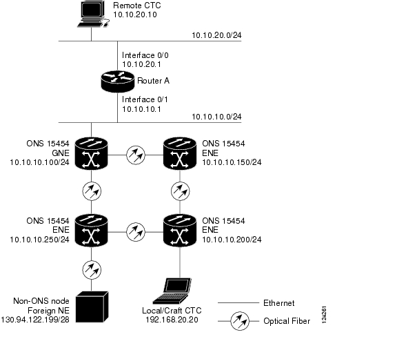
Figure 22-18 shows a remote node connected to an ENE Ethernet port. Proxy and firewall tunnels are useful in this example because the GNE would otherwise block IP access between the PC and foreign node. This configuration also requires a firewall tunnel on the ENE.
Figure 22-18 Foreign Node Connection to an ENE Ethernet Port
22.7 TCP/IP and OSI Networking
ONS 15454 DCN communication is based on the TCP/IP protocol suite. However, ONS 15454s can also be networked with equipment that uses the OSI protocol suite. While TCP/IP and OSI protocols are not directly compatible, they do have the same objectives and occupy similar layers of the OSI reference model. For detailed information about OSI protocols, processes, and scenarios, refer to the "Management Network Connectivity" chapter in the ONS 15454 Reference Manual. OSI/MSTP scenarios are provided in the following sections.
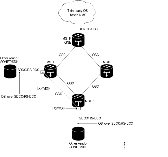
In OSI/MSTP Scenario 1 ( Figure 22-19), an SDCC or RS-DCC carries an OC-N signal from an OSI-based third party NE to an TXP/MXP card on an ONS NE. It is carried by GCC to a TXP/MXP card on another MSTP NE and then by SDCC or RS-DCC to a second third party NE. This scenario requires TXPs/MXPs whose client interfaces can be provisioned in section or line termination mode. These include:
•
•
•
OSI has to be carried or tunnelled to the other TXP/MXP through an OSC termination, GCC termination, or both. The third party NMS has OSI connectivity to its NEs with the MSTP ONS NE serving as the GNE for third party vendor OSI-based SONET equipment.
Figure 22-19 OSI/MSTP Scenario 1
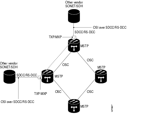
OSI/MSTP Scenario 2 ( Figure 22-20) is similar to Scenario 1, except the the MSTP NEs do not have connectivity to an OSI NMS.
Figure 22-20 OSI/MSTP Scenario 2
OSI/MSTP Scenario 3 ( Figure 22-21) shows the following:
•
•
•
•
Figure 22-21 OSI/MSTP Scenario 3
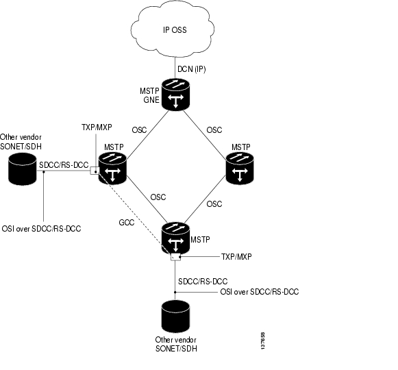
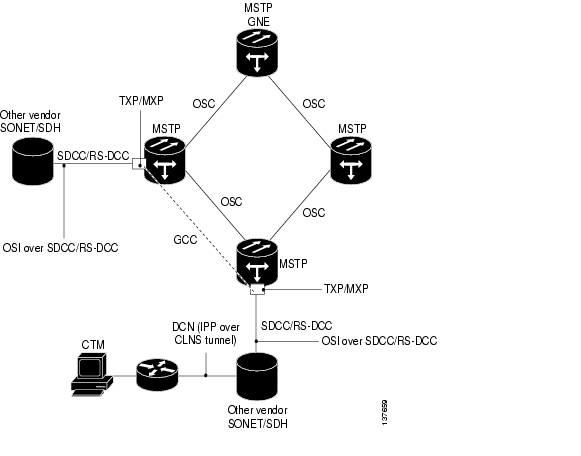
OSI/MSTP Scenario 4 ( Figure 22-22) shows the following:
•
•
•
•
•
Figure 22-22 OSI/IP Scenario 4
![]()
![]()
![]()
![]()
![]()
![]()
![]()
![]()
Posted: Mon Dec 3 03:29:23 PST 2007
All contents are Copyright © 1992--2007 Cisco Systems, Inc. All rights reserved.
Important Notices and Privacy Statement.