cc/td/doc/product/ong/15400/r60docs
hometocprevnextglossaryfeedbacksearchhelp
PDF

Table Of Contents

Provision Transponder and Muxponder Cards

Before You Begin

NTP-G128 Manage Pluggable Port Modules

DLP-G277 Provision a Multirate PPM

DLP-G274 Verify Topologies for ETR_CLO and ISC Services

DLP-G278 Provision the Optical Line Rate

DLP-G279 Change the Optical Line Rate

DLP-G280 Delete a PPM

NTP-G33 Create a Y-Cable Protection Group

NTP-G96 Modify Line Settings and PM Parameter Thresholds for TXP_MR_10G and TXP_MR_10E Cards

DLP-G216 Change Card Settings for TXP_MR_10G and TXP_MR_10E Cards

DLP-G217 Change Line Settings for TXP_MR_10G and TXP_MR_10E Cards

DLP-G218 Change Section Trace Settings for the TXP_MR_10G and TXP_MR_10E Cards

DLP-G219 Change the TXP_MR_10G or TXP_MR_10E Card Line Thresholds for SONET or SDH Payloads

DLP-G319 Change the TXP_MR_10G or TXP_MR_10E Card Line Thresholds for 10G Ethernet LAN Phy

DLP-G301 Provision the TXP_MR_10G and TXP_MR_10E Trunk Port Alarm and TCA Thresholds

DLP-G302 Provision the TXP_MR_10G and TXP_MR_10E Client Port Alarm and TCA Thresholds

DLP-G221 Change OTN Settings for TXP_MR_10G and TXP_MR_10E Cards

NTP-G97 Modify Line Settings and PM Parameter Thresholds for MXP_2.5G_10G and MXP_2.5G_10E Cards

DLP-G222 Change Card Settings for MXP_2.5G_10G and MXP_2.5G_10E Cards

DLP-G223 Change Line Settings for MXP_2.5G_10G and MXP_2.5G_10E Cards

DLP-G224 Change Section Trace Settings for MXP_2.5G_10G and MXP_2.5G_10E Cards

DLP-G225 Change Trunk Settings for MXP_2.5G_10G and MXP_2.5G_10E Cards

DLP-G226 Change Line Thresholds Settings for MXP_2.5G_10G and MXP_2.5G_10E Cards

DLP-G303 Provision the MXP_2.5G_10G and MXP_2.5G_10E Trunk Port Alarm and TCA Thresholds

DLP-G304 Provision the MXP_2.5G_10G and MXP_2.5G_10E Client Port Alarm and TCA Thresholds

DLP-G228 Change Line OTN Settings for MXP_2.5G_10G and MXP_2.5G_10E Cards

NTP-G98 Modify Line Settings and PM Parameter Thresholds for TXP_MR_2.5G and TXPP_MR_2.5G Cards

DLP-G229 Change Card Settings for TXP_MR_2.5G and TXPP_MR_2.5G Cards

DLP-G230 Change Line Settings for TXP_MR_2.5G and TXPP_MR_2.5G Cards

DLP-G231 Change Section Trace Settings for TXP_MR_2.5G and TXPP_MR_2.5G Cards

DLP-G232 Change TXP_MR_2.5G and TXPP_MR_2.5G Cards Line Threshold Settings for SONET or SDH Payloads

DLP-G320 Change the TXP_MR_2.5G or TXPP_MR_2.5G Card Line Thresholds for 1G Ethernet or 1G FC/FICON Payloads

DLP-G305 Provision the TXP_MR_2.5G and TXPP_MR_2.5G Trunk Port Alarm and TCA Thresholds

DLP-G306 Provision the TXP_MR_2.5G and TXPP_MR_2.5G Cards Client Port Alarm and TCA Thresholds

DLP-G234 Change OTN Settings for TXP_MR_2.5G and TXPP_MR_2.5G Cards

NTP-G99 Modify Line Settings and PM Parameter Thresholds for MXP_MR_2.5G and MXPP_MR_2.5G Cards

DLP-G235 Change Card Settings for MXP_MR_2.5G and MXPP_MR_2.5G Cards

DLP-G236 Change Client Line Settings for MXP_MR_2.5G and MXPP_MR_2.5G Cards

DLP-G237 Change Distance Extension Settings for MXP_MR_2.5G and MXPP_MR_2.5G Cards

DLP-G238 Change OC-48/STM-16 Settings for MXP_MR_2.5G and MXPP_MR_2.5G Cards

DLP-G239 Change Section Trace Settings for MXP_MR_2.5G and MXPP_MR_2.5G Cards

DLP-G240 Change MXP_MR_2.5G and MXPP_MR_2.5G Card Line Threshold Settings for SONET or SDH Payloads

DLP-G321 Change the MXP_MR_2.5G or MXPP_MR_2.5G Card Line Thresholds for 1G Ethernet or 1G FC/FICON Payloads

DLP-G307 Provision the MXP_MR_2.5G and MXPP_MR_2.5G Trunk Port Alarm and TCA Thresholds

DLP-G308 Provision the MXP_MR_2.5G and MXPP_MR_2.5G Client Port Alarm and TCA Thresholds


Provision Transponder and Muxponder Cards


This chapter explains how to provision transponder (TXP) and muxponder (MXP) cards. The provisioning must be performed before you provision the dense wavelength division multiplexing (DWDM) network and create circuits.


Note Unless otherwise specified, "ONS 15454" refers to both ANSI and ETSI shelf assemblies.


Before You Begin

Before performing any of the following procedures, investigate all alarms and clear any trouble conditions. Refer to the Cisco ONS 15454 Troubleshooting Guide or the Cisco ONS 15454 SDH Troubleshooting Guide as necessary.


Caution Provisioning TXPs and MXPs can be service affecting. You should make all changes during a scheduled maintenance window.

This section lists the chapter procedures (NTPs). Turn to a procedure for applicable tasks (DLPs).

1. G128 Manage Pluggable Port Modules—Complete this procedure to provision a multirate pluggable port module (PPM), provision or change the optical line rate of a PPM, or delete a PPM. PPMs provide the fiber interface to the TXP and MXP cards. With the exception of the TXP_MR_10G card, all TXPs and MXP accept PPMs.

2. G33 Create a Y-Cable Protection Group—Complete this procedure, as needed, for TXP and MXP cards that will be protected with Y-cable protection.

3. G96 Modify Line Settings and PM Parameter Thresholds for TXP_MR_10G and TXP_MR_10E Cards—As needed, complete this procedure to change the transmission settings for TXP_MR_10G and TXP_MR_10E cards.

4. G97 Modify Line Settings and PM Parameter Thresholds for MXP_2.5G_10G and MXP_2.5G_10E Cards—As needed, complete this procedure to change the transmission settings for MXP_2.5G_10G and MXP_2.5G_10E cards.

5. G98 Modify Line Settings and PM Parameter Thresholds for TXP_MR_2.5G and TXPP_MR_2.5G Cards—As needed, complete this procedure to change the transmission settings for TXP_MR_2.5G and TXPP_MR_2.5G cards.

6. G99 Modify Line Settings and PM Parameter Thresholds for MXP_MR_2.5G and MXPP_MR_2.5G Cards—As needed, complete this procedure to change the transmission settings for MXP_MR_2.5G and MXPP_MR_2.5G cards.

NTP-G128 Manage Pluggable Port Modules

Purpose

Complete this procedure to provision a multirate PPM, provision or change the optical line rate of a multirate PPM, or delete a PPM. If a single-rate PPM is installed, the PPM screen will autoprovision and no further steps are necessary.

Tools/Equipment

None

Prerequisite Procedures

DLP-G63 Install an SFP or XFP, page 3-45

Required/As Needed

As needed

Onsite/Remote

Onsite or remote

Security Level

Provisioning or higher


Note The hardware device that plugs into a TXP or MXP card faceplate to provide a fiber interface to the card is called a Small Form-factor Pluggable (SFP). In Cisco Transport Controller (CTC), SFPs are called PPMs.


Step 1 Complete the "DLP-G46 Log into CTC" task to log into an ONS 15454 on the network. If you are already logged in, continue with Step 2.

Step 2 Click the Alarms tab:

a. Verify that the alarm filter is not turned on. See the "DLP-G128 Disable Alarm Filtering" task as necessary.

b. Verify that no unexplained conditions appear on the network. If unexplained conditions appear, resolve them before continuing. Refer to the Cisco ONS 15454 Troubleshooting Guide or the Cisco ONS 15454 SDH Troubleshooting Guide.

c. Complete the "DLP-G114 Export CTC Data" task to export alarm and condition information.

Step 3 Complete the "DLP-G277 Provision a Multirate PPM" task. If you preprovisioned a multirate PPM ( DLP-G273 Preprovision an SFP or XFP Slot, page 3-46), skip this step and continue with Step 4. Single-rate PPMs do not require provisioning.

Step 4 If you are provisioning an IBM External Time Reference - Control Link Oscillator (ETR_CLO) or InterSystem Coupling link (ISC) service on the PPM, complete "DLP-G274 Verify Topologies for ETR_CLO and ISC Services" task. Otherwise, continue with Step 5.

Step 5 Complete the "DLP-G278 Provision the Optical Line Rate" task to assign a line rate to a TXP or MXP port.

Step 6 Complete the "DLP-G279 Change the Optical Line Rate" task as needed. Table 5-1 lists the available rates for each TXP and MXP card.

Step 7 Complete the "DLP-G280 Delete a PPM" task as needed.

Stop. You have completed this procedure.


DLP-G277 Provision a Multirate PPM

Purpose

This task provisions a multirate PPM in CTC. If the PPM was preprovisioned using the "DLP-G273 Preprovision an SFP or XFP Slot" task on page 3-46, or the SFP or XFP is physically installed, this task is unnecessary unless the PPM has an Out-of-Service and Autonomous Management, Unassigned (OOS-AUMA,UAS) (ANSI) or unlocked-disabled, unassigned (ETSI) service state.

Tools/Equipment

None

Prerequisite Procedures

G46 Log into CTC

Required/As Needed

Required

Onsite/Remote

Onsite or remote

Security Level

Provisioning or higher


Step 1 In node view, double-click the TXP or MXP card where you want to provision PPM settings.

Step 2 Click the Provisioning > Pluggable Port Modules tabs.

Step 3 In the Pluggable Port Modules area, click Create. The Create PPM dialog box appears.

Step 4 In the Create PPM dialog box, complete the following:

PPM—Choose the slot number where the SFP is installed from the drop-down list.

PPM Type—Choose the number of ports supported by your SFP from the drop-down list. If only one port is supported, PPM (1 port) is the only option.


Note The first port can be created only if the trunk is in the Out-of-Service and Management, Disabled (OOS-MA,DSBLD) service state (ANSI) (or the Locked-enabled,disabled service state [ETSI]).


Step 5 Click OK. The newly created port appears on the Pluggable Port Modules area. The row on the Pluggable Port Modules area turns white and the Actual Equipment Type column lists the equipment name.

Step 6 Verify that the PPM appears in the list on the Pluggable Port Modules area. If it does not, repeat Steps  3 through 5.

Step 7 Repeat the task to provision a second PPM.

Step 8 Return to your originating procedure (NTP).


DLP-G274 Verify Topologies for ETR_CLO and ISC Services

Purpose

This task verifies that the DWDM network topology can support the IBM ETR_CLO and ISC services. These services cannot be provisioned on all DWDM topologies.

Tools/Equipment

Cisco MetroPlanner site plan.

Prerequisite Procedures

None

Required/As Needed

As needed

Onsite/Remote

Onsite or remote

Security Level

Provisioning or higher


Step 1 Display your site plan in Cisco MetroPlanner.

Step 2 Verify that the topology where you plan to run the ETR_CLO or ISC service is one of the topologies that supports these services:

Single span—Two terminal sites with no intermediate sites in between and the following cards installed:

32MUX-O and 32DMX-O cards

32WSS and 32DMX cards

32WSS and 32-DMX-O cards

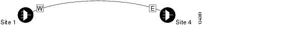
Figure 5-1 shows a single-span topology as displayed in Cisco MetroPlanner.

Figure 5-1 Single-Span Topology

Point-to-Point—Two terminal sites with the following cards installed:

32MUX-O and 32DMX-O cards

32WSS and 32DMX cards

32WSS and 32-DMX-O cards

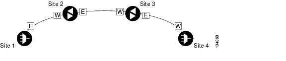
Line amplifiers can be installed between the terminal sites, but intermediate (traffic terminating) sites cannot be installed. Figure 5-2 shows a point-to-point topology as shown in Cisco MetroPlanner.

Figure 5-2 Point-to-Point Topology

Two hubs—Two hub nodes in a ring with the following cards installed:

32MUX-O and 32DMX-O cards

32WSS and 32DMX cards

32WSS and 32-DMX-O cards

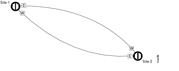
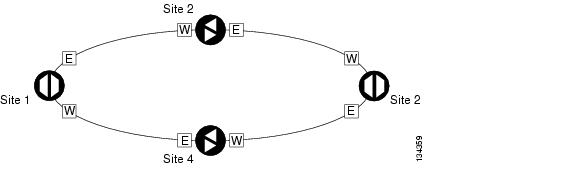
Line amplifiers can be installed between the hubs. Figure 5-3 shows two hub nodes with no line amplifier nodes installed. Figure 5-4 shows two hub nodes line amplifier nodes installed.

Figure 5-3 Hubs with No Line Amplifiers

Figure 5-4 Hubs with Line Amplifiers

Step 3 Return to your originating procedure (NTP).


DLP-G278 Provision the Optical Line Rate

Purpose

This task provisions the line rate on a multirate PPM. Single-rate PPMs do not need to be provisioned.

Tools/Equipment

None

Prerequisite Procedures

G277 Provision a Multirate PPM

G274 Verify Topologies for ETR_CLO and ISC Services, if you are provisioning an ETR_CLO service.

G46 Log into CTC

Required/As Needed

Required

Onsite/Remote

Onsite or remote

Security Level

Provisioning or higher


Step 1 In node view, double-click the TXP or MXP card where you want to provision PPM ports. If the data rate you are provisioning is DV-6000, HDTV, ESCON, SDI/D1 Video, ISC-3, or ETR_CLO, complete the following steps. Otherwise, continue with Step 2.

a. Click the Provisioning > OTN > OTN Lines tabs.

b. In the G.709 OTN field, choose Disable.

c. In the FEC field, choose Disable.

d. Click Apply.

Step 2 Click the Provisioning > Pluggable Port Modules tabs.

Step 3 In the Pluggable Ports area, click Create. The Create Port dialog box appears.

Step 4 In the Create Port dialog box, complete the following:

Port—Choose the PPM number and port number from the drop-down list. The first number indicates the PPM and the second number indicates the port number on the PPM. For example, the first PPM with one port displays as 1-1 and the second PPM with one port displays as 2-1. The PPM number can be 1 to 4, but the port number is always 1.

Port Type—Choose the type of port from the drop-down list. The port type list displays the supported port rates on your PPM. See Table 5-1 for definitions of the supported rates on the TXP or MXP card.

Step 5 Click OK. The row on the Pluggable Ports area turns light blue until the actual SFP is installed, and then the row turns white.

Step 6 Repeat Steps 3 through 5 to configure the port rates as needed.

Table 5-1 PPM Port Types 

Card
Port Type

TXP_MR_2.5G and TXPP_MR_2.5G

OC-3/STM1—155 Mbps

OC-12/STM4—622 Mbps

OC-48/STM16—2.48 Gbps

ONE_GE—One Gigabit Ethernet 1.125 Gbps

ESCON—Enterprise System Connection (IBM signal)

DV6000—Proprietary signal from video vendor

SDI_D1_VIDEO—Serial Digital Interface and Digital Video signal type 1

HDTV—High Definition Television

PASS-THRU—Not specified

FC1G—Fibre Channel 1.06 Gbps

FC2G—Fibre Channel 2.125 Gbps

FICON1G—Fiber CON 1.06 Gbps (IBM signal)

FICON2G—Fiber CON 2.125 Gbps (IBM signal)

ETR_CLO—External Time Reference - Control Link Oscillator

ISC compat—InterSystem Coupling Link 1 (ISC1)

ISC peer—InterSystem Coupling Link 3 (ISC3)

MXP_2.5G_10G and MXP_2.5G_10E

OC-48/STM16—2.48 Gbps

TXP_MR_10E

OC-192/STM-64—10 Gbps

10G Ethernet LAN Phy—10 Gbps Ethernet

10G Fibre Channel—10 Gbps Fibre Channel

MXP_MR_2.5G and MXPP_MR_2.5G

FC1G—Fibre Channel 1.06 Gbps

FC2G—Fibre Channel 2.125 Gbps

FICON1G—Fiber CON 1.06 Gbps (IBM signal)

FICON2G—Fiber CON 2.125 Gbps (IBM signal)

ONE_GE—One Gigabit Ethernet 1.125 Gbps


Note The TXP_MR_10G card is the only TXP or MXP card that does not accept PPMs.


Step 7 Return to your originating procedure (NTP).


DLP-G279 Change the Optical Line Rate

Purpose

This task edits PPM port rates for the TXP and MXP cards. Perform this task if you want to change the port rate on a multirate PPM that is already provisioned.

Tools/Equipment

None

Prerequisite Procedures

G277 Provision a Multirate PPM

G46 Log into CTC

Required/As Needed

As needed

Onsite/Remote

Onsite or remote

Security Level

Provisioning or higher


Step 1 In node view, double-click the TXP or MXP card where you want to edit the PPM port rate.

Step 2 Click the Provisioning > Pluggable Port Modules tabs.

Step 3 Click the port with the port rate you that want to change in the Pluggable Ports area. The highlight changes to dark blue.

Step 4 Click Edit. The Edit Port Rate dialog box appears.

Step 5 In the Change To field, use the drop-down list to select the new port rate and click OK. Table 5-1 lists the available rates.

Step 6 Click Yes in the Confirm Port Rate Change dialog box.

Step 7 Return to your originating procedure (NTP).


DLP-G280 Delete a PPM

Purpose

This task deletes PPM provisioning for SFPs or XFPs installed on TXP or MXP cards.

Tools/Equipment

None

Prerequisite Procedures

G46 Log into CTC

DLP-G63 Install an SFP or XFP, page 3-45 or

DLP-G273 Preprovision an SFP or XFP Slot, page 3-46

Required/As Needed

As needed

Onsite/Remote

Onsite or remote

Security Level

Provisioning or higher


Note This task does not apply to the TXP_MR_10G card.


Step 1 In node view, double-click the TXP or MXP card where you want to delete PPM settings.

Step 2 Click the Provisioning > Pluggable Port Modules tabs.

Step 3 To delete a PPM and the associated ports:


Note You cannot delete a port if the client is in the In Service and Normal (IS-NR) (ANSI) or Unlocked-enabled (ETSI) service state, is part of a protection group, has a generic communications channel (GCC) or data communications channel (DCC) in use, is used as a timing source, has circuits, or has overhead circuits. You can delete a port if the trunk is in service and the client is in the OOS-MA,DSBLD (ANSI)/Locked-enabled,disabled (ETSI) service state, with the exception of the last port. You can delete the last port only if the trunk is in a OOS-MA,DSBLD (ANSI)/Locked-enabled,disabled (ETSI) service state.


a. Click the PPM line that you want to delete that appears in the Pluggable Port Modules area. The highlight changes to dark blue.

b. Click Delete. The Delete PPM dialog box appears.

c. Click Yes. The PPM provisioning is removed from the Pluggable Port Modules area and the Pluggable Ports area.

Step 4 Verify that the PPM provisioning is deleted:

CTC shows an empty slot after the PPM is deleted.

If the SFP or XFP is physically present when you delete the PPM provisioning, CTC transitions to the deleted state, the ports (if any) are deleted, and the PPM is represented as a gray graphic in CTC. The SFP or XFP can be provisioned again in CTC, or the equipment can be removed, in which case the removal causes the graphic to disappear.

Step 5 If you need to remove the PPM hardware (the SFP or XFP), complete the "DLP-G64 Remove an SFP or XFP" task on page 3-47.

Step 6 Return to your originating procedure (NTP).


NTP-G33 Create a Y-Cable Protection Group

Purpose

This procedure creates a Y-cable protection group between the client ports of two transponder (TXP_MR_10G, TXP_MR_10E, or TXP_MR_2.5G) or two muxponder (MXP_2.5G_10G, MXP_2.5G_10E, MXP_MR_2.5G, MXPP_MR_2.5G) cards. For additional information about Y-cable protection, see the "16.9.1  Y-Cable Protection" section on page 16-114.

Tools/Equipment

Installed TXP or MXP cards.

Cisco MetroPlanner Traffic Matrix

Prerequisite Procedures

NTP-G15 Install the Common Control Cards, page 1-71

NTP-G14 Install DWDM Equipment, page 1-66

G46 Log into CTC

NTP-G139 Verify Cisco MetroPlanner Reports and Files, page 3-3

Required/As Needed

As needed

Onsite/Remote

Onsite or remote

Security Level

Provisioning or higher


Note Loss of Pointer Path (LOP-P) alarms can occur on a split signal if the ports are not in a Y-cable protection group.


Step 1 View the Cisco MetroPlanner Traffic Matrix (see Table 3-1 on page 3-3) for your site. Verify the TXP or MXP cards that need Y-cable protection groups. (Cards requiring Y-cable protection are indicated with "Y-Cable" in the Traffic Matrix table Protection Type column. Refer to the Cisco MetroPlanner DWDM Operations Guide for more information.)

Step 2 Verify that the TXP or MXP cards are installed according to the requirements specified in Table 5-2. This table describes the protection types available in the ONS 15454 for DWDM client cards.

Table 5-2 Protection Types

Type
Cards
Description and Installation Requirements

Y-cable

MXP_2.5_10G

MXP_2.5_10E

TXP_MR_10G

TXP_MR_10E

TXP_MR_2.5G

MXP_MR_2.5G

Pairs a working transponder or muxponder card/port with a protect transponder or muxponder card/port. The protect port must be on a different card than the working port and it must be the same card type as the working port. The working and protect port numbers must be the same, that is, Port 1 can only protect Port 1, Port 2 can only protect Port 2, etc.

Splitter

TXPP_MR_2.5G

MXPP_MR_2.5G

A splitter protection group is automatically created when a TXPP_MR_2.5G or MXPP_MR_2.5G card is installed. You can edit the splitter protection group name.


Step 3 Verify that PPMs are provisioned for the same payload and payload rate on the TXP and MXP cards where you will create the Y-cable protection group.

Display the TXP or MXP card in card view. Click the Provisioning > Pluggable Port Module tabs. Verify that a PPM is provisioned in the Pluggable Port Module area, and the payload type and rate is provisioned for it in the Selected PPM area.

The PPM payload and payload rate must be the same for both TXP or MXP cards. If they are not the same, for example, if the PPM payload and payload rate are not the same, you must either change the provisioned payload rate to match, or replace the PPM (SFP or XFP).

Step 4 In node view, click the Provisioning > Protection tabs.

Step 5 In the Protection Groups area, click Create.

Step 6 In the Create Protection Group dialog box, enter the following:

Name—Type a name for the protection group. The name can have up to 32 alphanumeric (a-z, A-Z, 0-9) characters. Special characters are permitted. For TL1 compatibility, do not use question mark (?), backslash (\), or double quote (") characters.

Type—Choose Y Cable from the drop-down list.

Protect Port—From the drop-down list, choose the port that will be the standby or protection port to the active port. The list displays the available transponder or muxponder ports. If transponder or muxponder cards are not installed, no ports appear in the drop-down list.

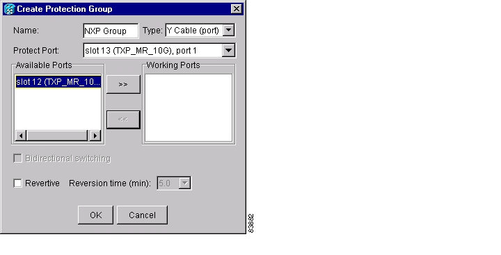
After you choose the protect port, a list of available working ports appear in the Available Ports list, as shown in Figure 5-5. If no cards are available, no ports appear. If this occurs, you can not complete this task until you install the physical cards or preprovision the ONS 15454 slots using the "NTP-G29 Preprovision a Slot" procedure on page 3-37.

Figure 5-5 Creating a Y-Cable Protection Group

Step 7 From the Available Ports list, choose the port that will be protected by the port you selected in Protect Ports. Click the top arrow button to move the port to the Working Ports list.

Step 8 Complete the remaining fields:

Revertive—Check this check box if you want traffic to revert to the working port after failure conditions remain corrected for the amount of time entered in the Reversion Time field.

Reversion time—If Revertive is checked, select a reversion time from the drop-down list. The range is 0.5 to 12.0 minutes. The default is 5.0 minutes. Reversion time is the amount of time that will elapse before the traffic reverts to the working card. The reversion timer starts after conditions causing the switch are cleared.

Step 9 Click OK.

Step 10 Repeat this procedure for every protection indicated in the Cisco MetroPlanner Traffic Matrix.

Stop. You have completed this procedure.


NTP-G96 Modify Line Settings and PM Parameter Thresholds for TXP_MR_10G and TXP_MR_10E Cards

Purpose

This procedure changes the line and threshold settings for TXP_MR_10G and TXP_MR_10E cards.

Tools/Equipment

None

Prerequisite Procedures

NTP-G32 Install the Transponder and Muxponder Cards, page 3-43

DLP-G63 Install an SFP or XFP, page 3-45

G277 Provision a Multirate PPM (if necessary)

G278 Provision the Optical Line Rate (if necessary)

Required/As Needed

As needed

Onsite/Remote

Onsite or remote

Security Level

Provisioning or higher


Note The TXP_MR_10G card does not support PPMs.


Step 1 Complete the "DLP-G46 Log into CTC" task at the node where you want to change the transponder card settings. If you are already logged in, continue with Step 2.

Step 2 As needed, complete the "NTP-G103 Back Up the Database" procedure on page 13-2 to preserve the existing transmission settings.

Step 3 Perform any of the following tasks as needed:

G216 Change Card Settings for TXP_MR_10G and TXP_MR_10E Cards

G217 Change Line Settings for TXP_MR_10G and TXP_MR_10E Cards

G218 Change Section Trace Settings for the TXP_MR_10G and TXP_MR_10E Cards

G219 Change the TXP_MR_10G or TXP_MR_10E Card Line Thresholds for SONET or SDH Payloads

G319 Change the TXP_MR_10G or TXP_MR_10E Card Line Thresholds for 10G Ethernet LAN Phy

G301 Provision the TXP_MR_10G and TXP_MR_10E Trunk Port Alarm and TCA Thresholds

G302 Provision the TXP_MR_10G and TXP_MR_10E Client Port Alarm and TCA Thresholds

G221 Change OTN Settings for TXP_MR_10G and TXP_MR_10E Cards

Stop. You have completed this procedure.


DLP-G216 Change Card Settings for TXP_MR_10G and TXP_MR_10E Cards

Purpose

This task changes the card settings for TXP_MR_10G and TXP_MR_10E multirate (10 Gbps) transponder cards.

Tools/Equipment

None

Prerequisite Procedures

G46 Log into CTC

Required/As Needed

As needed

Onsite/Remote

Onsite or remote

Security Level

Provisioning or higher


Step 1 In node view, double-click the TXP_MR_10G or TXP_MR_10E card where you want to change the card settings.

Step 2 Click the Provisioning > Card tabs.

Step 3 Modify any of the settings described in Table 5-3.

Table 5-3 TXP_MR-10G and TXP_MR_10E Card Settings

Parameter
Description
Options - ONS 15454
Options - ONS 15454 SDH

Termination Mode

Sets the mode of operation. See the "16.12  Termination Modes" section on page 16-117 for more details.

Transparent

Section (TXP_MR_10E only)

Line

Transparent

Regeneration Section (TXP_MR_10E only)

Multiplex Section

AIS/Squelch
Configuration

(TXP_MR_10E only) Sets the transparent termination mode configuration.

Squelch

AIS

Squelch

AIS

Wavelength

Sets the wavelength of the DWDM side optical transmitter.

First Tunable Wavelength

Further wavelengths in 100-GHz ITU spacing

Supported wavelengths are in white and marked by asterisks (**); unsupported wavelengths are gray.

Note The four available wavelengths are listed in the Card Parameters section of the window and also on the Maintenance > Info tab.


Step 4 Click Apply.

Step 5 Return to your originating procedure (NTP).


DLP-G217 Change Line Settings for TXP_MR_10G and TXP_MR_10E Cards

Purpose

This task changes the line settings for TXP_MR_10G and TXP_MR_10E transponder cards.

Tools/Equipment

None

Prerequisite Procedures

G46 Log into CTC

Required/As Needed

As needed

Onsite/Remote

Onsite or remote

Security Level

Provisioning or higher


Step 1 In node view, double-click the TXP_MR_10G or TXP_MR_10E card where you want to change the line settings.

Step 2 Click the Provisioning > Line > SONET (including 10G Ethernet WAN phy) tabs.

Step 3 Modify any of the settings described in Table 5-4.


Note In Table 5-4, some parameter tabs do not always apply to both the TXP_MR_10G cards and the TXP_MR_10E cards. If a tab does not apply, it will not appear in CTC.


Table 5-4 TXP_MR_10G and TXP_MR_10E Transponder Card Line Settings 

Parameter
Description
Options - ONS 15454
Options - ONS 15454 SDH

Port

(Display only) Displays the port number.

1-1 (OC192)

2 (Trunk)

1-1 (STM64)

2 (Trunk)

Port Name

Provides the ability to assign the specified port a name.

User-defined. Name can be up to 32 alphanumeric/special characters. Blank by default.

See the "DLP-G104 Assign a Name to a Port" task.

User-defined. Name can be up to 32 alphanumeric/special characters. Blank by default.

See the "DLP-G104 Assign a Name to a Port" task.

Admin State

Sets the port service state. For more information about administrative states, see "DWDM Administrative and Service States."

IS

IS,AINS

OOS,DSBLD

OOS,MT

Unlocked

Unlocked,automaticInService

Locked,disabled

Locked,maintenance

Service State

(Display only) Identifies the autonomously generated state that gives the overall condition of the port. Service states appear in the format: Primary State-Primary State Qualifier, Secondary State. For more information about service states, see "DWDM Administrative and Service States."

IS-NR

OOS-AU,AINS

OOS-MA,DSBLD

OOS-MA,MT

Unlocked-enabled

Unlocked-disabled,
automaticInService

Locked-enabled,disabled

Locked-enabled,maintenance

SF BER

(SONET [ANSI] or SDH [ETSI] including 10G Ethernet WAN Phy only) Sets the signal fail bit error rate.

1E-3

1E-4

1E-5

1E-3

1E-4

1E-5

SD BER

(SONET [ANSI] or SDH [ETSI] including 10G Ethernet WAN Phy only) Sets the signal degrade bit error rate.

1E-5

1E-6

1E-7

1E-8

1E-9

1E-5

1E-6

1E-7

1E-8

1E-9

AINS Soak

(SONET [ANSI] or SDH [ETSI] including 10G Ethernet WAN Phy only) Sets the automatic in-service soak period. Double-click the time and use the up and down arrows to change settings.

Duration of valid input signal, in hh.mm format, after which the card becomes in service (IS) automatically

0 to 48 hours, 15-minute increments

Duration of valid input signal, in hh.mm format, after which the card becomes in service (IS) automatically

0 to 48 hours, 15-minute increments

Type

(SONET [ANSI] or SDH [ETSI] including 10G Ethernet WAN Phy only) The optical transport type.

SONET

SDH

SONET

SDH

ALS Mode

Sets the automatic laser shutdown (ALS) function mode. The DWDM transmitter supports ALS according to ITU-T G.644 (06/99). ALS can be disabled, or it can be set for one of three mode options.

Disable (default): ALS is off; the laser is not automatically shut down when traffic outages (LOS) occur.

Auto Restart: ALS is on; the laser automatically shuts down when traffic outages (LOS) occur. It automatically restarts when the conditions that caused the outage are resolved.

Manual Restart: ALS is on; the laser automatically shuts down when traffic outages (LOS) occur. However, the laser must be manually restarted when conditions that caused the outage are resolved.

Manual Restart for Test: Manually restarts the laser for testing.

ProvidesSync

(TXP_MR_10E, OC192 only) Sets the ProvidesSync card parameter. If checked, the card is provisioned as a network element (NE) timing reference.

Checked or unchecked

Checked or unchecked

SyncMsgIn

(TXP_MR_10E, OC192 only) Sets the EnableSync card parameter. Enables synchronization status messages (S1 byte), which allow the node to choose the best timing source.

Checked or unchecked

Checked or unchecked

Send DoNotUse

(TXP_MR_10E, OC192 only) Sets the Send DoNotUse card state. When checked, sends a do not use (DUS) message on the S1 byte.

Checked or unchecked

Checked or unchecked

Max Size

(TXP_MR_10E, 10_GE LAN Phy only) Sets the maximum Ethernet packet size.

1548 bytes

Jumbo (64 to 9,216 bytes)

1548 bytes

Jumbo (64 to 9,216 bytes)

Incoming MAC Address

(TXP_MR_10E, 10_GE LAN Phy only) Sets the incoming MAC address.

Value of MAC address. 6 bytes in hexadecimal format.

Value of MAC address. 6 bytes in hexadecimal format.

Wavelength

Displays the wavelength of the client port.

First Tunable Wavelength

Further wavelengths:
1310 nm to 1550 nm
100-GHz ITU spacing
Coarse wavelength division multiplexing (CWDM) spacing

Supported wavelengths are marked by asterisks (**)

First Tunable Wavelength

Further wavelengths:
1310 nm to 1550 nm
100-GHz ITU spacing
CWDM spacing

Supported wavelengths are marked by asterisks (**)

Reach

Displays the optical reach distance of the client port.

The Reach options depend on the traffic type that has been selected

The Reach options depend on the traffic type that has been selected


Step 4 Click Apply.

Step 5 Return to your originating procedure (NTP).


DLP-G218 Change Section Trace Settings for the TXP_MR_10G and TXP_MR_10E Cards

Purpose

This task changes the section trace settings for the TXP_MR_10G and TXP_MR_10E transponder cards.

Tools/Equipment

None

Prerequisite Procedures

G46 Log into CTC

Required/As Needed

As needed

Onsite/Remote

Onsite or remote

Security Level

Provisioning or higher


Note The Section Trace tab is available for the TXP_MR_10G and TXP_MR_10E cards only if no PPM or an OC192 PPM has been provisioned. The tab is not available if a TEN_GE LAN Phy or FC10G PPM has been provisioned.


Step 1 In node view, double-click the TXP_MR_10G or TXP_MR_10E card where you want to change the section trace settings.

Step 2 Click the Provisioning > Line > Section Trace tabs.

Step 3 Modify any of the settings described in Table 5-5.

Table 5-5 TXP_MR_10G and TXP_MR_10E Transponder Card Section Trace Settings 

Parameter
Description
Options - ONS 15454
Options — ONS 15454 SDH

Port

Sets the port number.

1-1 (OC192)

2—Trunk

1-1 (STM64)

2—Trunk

Trace Mode

Sets the trace mode.

Off/None

Manual

Off/None

Manual

Section Trace String Size

Sets the trace string size.

1 byte

16 byte

1 byte

16 byte

Transmit

Displays the current transmit string; sets a new transmit string. You can click the button on the right to change the display. Its title changes, based on the current display mode. Click Hex to change the display to hexadecimal (button changes to ASCII); click ASCII to change the display to ASCII (button changes to Hex).

String of trace string size

String of trace string size

Expected

Displays the current transmit string; sets a new transmit string. You can click the button on the right to change the display. Its title changes, based on the current display mode. Click Hex to change the display to hexadecimal (button changes to ASCII); click ASCII to change the display to ASCII (button changes to Hex).

String of trace string size

String of trace string size

Received

(Display only) Displays the current received string. You can click Refresh to manually refresh this display, or check the Auto-refresh every 5 sec check box to keep this field updated.

String of trace string size

String of trace string size


Step 4 Click Apply.

Step 5 Return to your originating procedure (NTP).


DLP-G219 Change the TXP_MR_10G or TXP_MR_10E Card Line Thresholds for SONET or SDH Payloads

Purpose

This task changes the line threshold settings for TXP_MR_10G and TXP_MR_10E transponder cards carrying SONET or SDH payloads, including the physical 10G Ethernet WAN payload.

Tools/Equipment

None

Prerequisite Procedures

G46 Log into CTC

Required/As Needed

As needed

Onsite/Remote

Onsite or remote

Security Level

Provisioning or higher


Step 1 In node view, double-click the TXP_MR_10G or TXP_MR_10E card where you want to change the line threshold settings.

Step 2 Click the Provisioning > Line Thresholds > SONET Thresholds tabs.

Step 3 Modify any of the settings described in Table 5-6.


Note You must modify Near End and Far End independently; 15 Min and 1 Day independently; and Line and Section independently. To do so, choose the appropriate radio button and click Refresh.


Table 5-6 TXP_MR_10G and TXP_MR_10E Transponder Card Line Threshold Settings 

Parameter
Description
Options - ONS 15454
Options - ONS 15454 SDH

Port

(Display only) Port number

1-1 (OC192)

2 (Trunk)

1-1 (STM64)

2 (Trunk)

CV

Coding violations

Numeric. Threshold display options include:

Direction—Near End or Far End

Interval—15 Min (minutes) or 1 day

Types—Line or Section (near end only)

Choose an option in each category and click Refresh.

Numeric. Threshold display options include:

Direction—Near End or Far End

Interval—15 Min (minutes) or 1 day

Types—Multiplex Section or Regeneration Section (near end only)

Choose an option in each category and click Refresh.

ES

Errored seconds

Numeric. Threshold display options include:

Direction—Near End or Far End

Interval—15 Min (minutes) or 1 day

Types—Line or Section (near end only)

Choose an option in each category and click Refresh.

Numeric. Threshold display options include:

Direction—Near End or Far End

Interval—15 Min (minutes) or 1 day

Types—Multiplex Section or Regeneration Section (near end only)

Choose an option in each category and click Refresh.

SES

Severely errored seconds

Numeric. Threshold display options include:

Direction—Near End or Far End

Interval—15 Min (minutes) or 1 day

Types—Line or Section (near end only)

Choose an option in each category and click Refresh.

Numeric. Threshold display options include:

Direction—Near End or Far End

Interval—15 Min (minutes) or 1 day

Types—Multiplex Section or Regeneration Section (near end only)

Choose an option in each category and click Refresh.

SEFS

(Section only) Severely errored framing seconds

Numeric. Can be set for Far End for 15-minute or one-day intervals for Section only. Choose an interval option and click Refresh.

Numeric. Can be set for Far End for 15-minute or one-day intervals for Regeneration Section only. Choose an interval option and click Refresh.

FC

Failure count

Numeric. Threshold display options include:

Direction—Near End or Far End

Interval—15 Min (minutes) or 1 day

Types—Line or Section (near end only)

Choose an option in each category and click Refresh.

Numeric. Threshold display options include:

Direction—Near End or Far End

Interval—15 Min (minutes) or 1 day

Types—Multiplex Section or Regeneration Section (near end only)

Choose an option in each category and click Refresh.

UAS

Unavailable seconds

Numeric. Threshold display options include:

Direction—Near End or Far End

Interval—15 Min (minutes) or 1 day

Types—Line or Section (near end only)

Choose an option in each category and click Refresh.

Numeric. Threshold display options include:

Direction—Near End or Far End

Interval—15 Min (minutes) or 1 day

Types—Multiplex Section or Regeneration Section (near end only)

Choose an option in each category and click Refresh.


Step 4 Click Apply.

Step 5 Return to your originating procedure (NTP).


DLP-G319 Change the TXP_MR_10G or TXP_MR_10E Card Line Thresholds for 10G Ethernet LAN Phy

Purpose

This task changes the line threshold settings for TXP_MR_10G and TXP_MR_10E transponder cards carrying the physical 10G Ethernet LAN payload.

Tools/Equipment

None

Prerequisite Procedures

G46 Log into CTC

Required/As Needed

As needed

Onsite/Remote

Onsite or remote

Security Level

Provisioning or higher


Step 1 Display the TXP_MR_10G or TXP_MR_10E card where you want to change the line threshold settings in card view.

Step 2 Click the Provisioning > Line Thresholds > RMON Thresholds tabs.

Step 3 Click Create. The Create Threshold dialog box appears.

Step 4 From the Port drop-down list, choose the applicable port.

Step 5 From the Variable drop-down list, choose an Ethernet variable. See Table 5-7 for a list of available Ethernet thresholds.

Table 5-7 TXP_MR_10G and TXP_MR 10GE LAN Phy Variables 

Variable
Description

ifInOctets

Total number of octets received on the interface, including framing characters.

rxTotalPkts

Total number of received packets.

ifInMulticastPkts

Number of multicast frames received error free.

ifInBroadcastPkts

Number of packets, delivered by a sublayer to an higher sublayer, which were addressed to a broadcast address at this sublayer.

ifInErrors

Number of inbound packets that contained errors preventing them from being delivered to a higher-layer protocol.

ifInErrorBytePkts

Number of receive error bytes.

ifInFramingErrorPkts

Number of receive framing error counters.

ifInJunkInterPkts

Number of receive interpacket junk counters.

ifOutOctets

Total number of octets transmitted out of the interface, including framing characters.

txTotalPkts

Total number of transmit packets.

ifOutMulticastPkts

Number of multicast frames transmitted error free.

ifOutBroadcastPkts

Total number of packets that higher-level protocols requested be transmitted, and that were addressed to a broadcast address at this sublayer, including those that were discarded or not sent.

dot3StatsFCSErrors

Number of frames with frame check errors, that is, there is an integral number of octets, but an incorrect Frame Check Sequence (FCS).

dot3StatsFrameTooLong

Number of received frames that were larger than the maximum size permitted.

etherStatsUndersizePkts

Total number of packets received that were less than 64 octets long (excluding framing bits, but including FCS octets) and were otherwise well formed.

etherStatsFragments

Total number of packets received that were less than 64 octets in length (excluding framing bits but including FCS octets) and had either a bad FCS with an integral number of octets (FCS Error) or a bad FCS with a nonintegral number of octets (Alignment Error). Note that it is entirely normal for etherStatsFragments to increment. This is because it counts both runts (which are normal occurrences due to collisions) and noise hits.

etherStatsPkts64Octets

Total number of packets (including bad packets) received that were 64 octets in length (excluding framing bits but including FCS octets).

etherStatsPkts65to127Octets

Total number of packets (including bad packets) received that were between 65 and 127 octets in length inclusive (excluding framing bits but including FCS octets).

etherStatsPkts128to255Octets

The total number of packets (including bad packets) received that were between 128 and 255 octets in length inclusive (excluding framing bits but including FCS octets).

etherStatsPkts256to511Octets

Total number of packets (including bad packets) received that were between 256 and 511 octets in length inclusive (excluding framing bits but including FCS octets).

etherStatsPkts512to1023Octets

Total number of packets (including bad packets) received that were between 512 and 1023 octets in length inclusive (excluding framing bits but including FCS octets).

etherStatsPkts1024to1518Octets

Total number of packets (including bad packets) received that were between 1024 and 1518 octets in length inclusive (excluding framing bits but including FCS octets).

etherStatsBroadcastPkts

Total number of good packets received that were directed to the broadcast address. Note that this does not include multicast packets.

etherStatsMulticastPkts

Total number of good packets received that were directed to a multicast address. Note that this number does not include packets directed to the broadcast address.

etherStatsOversizePkts

Total number of packets received that were longer than 1518 octets (excluding framing bits, but including FCS octets) and were otherwise well formed.

etherStatsJabbers

Total number of packets received that were longer than 1518 octets (excluding framing bits, but including FCS octets), and had either a bad FCS with an integral number of octets (FCS Error) or a bad FCS with a nonintegral number of octets (Alignment Error).

etherStatsOctets

Total number of octets of data (including those in bad packets) received on the network (excluding framing bits but including FCS octets).

etherStatsCRCAlignErrors

Total number of packets received that had a length (excluding framing bits, but including FCS octets) of between 64 and 1518 octets, inclusive, but had either a bad FCS with an integral number of octets (FCS Error) or a bad FCS with a nonintegral number of octets (Alignment Error).

rxPauseFrames

Number of received IETF 802.x pause frames

rxControlFrames

Number of MAC control frames passed by the MAC sublayer to the MAC control sublayer.

rxUnknownOpcodeFrames

Number of MAC control frames received that contain an opcode that is not supported by the device.


Step 6 From the Alarm Type drop-down list, indicate whether the event will be triggered by the rising threshold, falling threshold, or both the rising and falling thresholds.

Step 7 From the Sample Type drop-down list, choose either Relative or Absolute. Relative restricts the threshold to use the number of occurrences in the user-set sample period. Absolute sets the threshold to use the total number of occurrences, regardless of time period.

Step 8 Type in an appropriate number of seconds for the Sample Period.

Step 9 Type in the appropriate number of occurrences for the Rising Threshold.

For a rising type of alarm, the measured value must move from below the falling threshold to above the rising threshold. For example, if a network is running below a rising threshold of 1000 collisions every 15 seconds and a problem causes 1001 collisions in 15 seconds, the excess occurrences trigger an alarm.

Step 10 Enter the appropriate number of occurrences in the Falling Threshold field. In most cases a falling threshold is set lower than the rising threshold.

A falling threshold is the counterpart to a rising threshold. When the number of occurrences is above the rising threshold and then drops below a falling threshold, it resets the rising threshold. For example, when the network problem that caused 1001 collisions in 15 seconds subsides and creates only 799 collisions in 15 seconds, occurrences fall below a falling threshold of 800 collisions. This resets the rising threshold so that if network collisions again spike over a 1000 per 15-second period, an event again triggers when the rising threshold is crossed. An event is triggered only the first time a rising threshold is exceeded (otherwise, a single network problem might cause a rising threshold to be exceeded multiple times and cause a flood of events).

Step 11 Click OK.

Step 12 Return to your originating procedure (NTP).


DLP-G301 Provision the TXP_MR_10G and TXP_MR_10E Trunk Port Alarm and TCA Thresholds

Purpose

This task provisions the TXP_MR_10G and TXP_MR_10E trunk port alarm and threshold crossing alert (TCA) thresholds.

Tools/Equipment

None

Prerequisite Procedures

G46 Log into CTC

Required/As Needed

As needed

Onsite/Remote

Onsite or remote

Security Level

Provisioning or higher


Step 1 In node view, double-click the TXP_MR_10G or TXP_MR_10E card where you want to change the trunk port alarm and TCA settings.

Step 2 Click the Provisioning > Optics Thresholds tabs.

Step 3 Referring to Table 5-8, provision the trunk port (Port 2) TCA thresholds for RX Power High, RX Power Low, TX Power High, and TX Power Low.


Note You must modify 15 Min and 1 Day independently. To do so, choose the appropriate radio button and click Refresh.


Note Do not modify the Laser Bias parameters.


Step 4 Click Apply.

Table 5-8 TXP_MR_10G and TXP_MR_10E Trunk Port TCA Thresholds 

Card
TCA RX
Power Low
TCA RX
Power High
TCA TX
Power Low
TCA TX
Power High

TXP_MR_10G

-22 dBm

-8 dBm

-1 dBm

7 dBm

TXP_MR_10E

-18 dBm

-9 dBm

0 dBm

9 dBm


Step 5 Under Types, click the Alarm radio button and click Refresh.

Step 6 Referring to Table 5-9, provision the trunk port (Port 2) Alarm thresholds for RX Power High, RX Power Low, TX Power High, and TX Power Low.


Note You must modify 15 Min and 1 Day independently. To do so, choose the appropriate radio button and click Refresh.


Step 7 Click Apply.

Table 5-9 TXP_MR_10G and TXP_MR_10E Trunk Port Alarm Thresholds 

Card
Alarm RX
Power Low
Alarm RX
Power High
Alarm TX
Power Low
Alarm TX
Power High

TXP_MR_10G

-24 dBm

-8 dBm

2 dBm

4 dBm

TXP_MR_10E

-20 dBm

-8 dBm

3 dBm

7 dBm


Step 8 Return to your originating procedure (NTP).


DLP-G302 Provision the TXP_MR_10G and TXP_MR_10E Client Port Alarm and TCA Thresholds

Purpose

This task provisions the client port alarm and TCA thresholds for the TXP_MR_10G and TXP_MR_10E cards.

Tools/Equipment

None

Prerequisite Procedures

G278 Provision the Optical Line Rate

G46 Log into CTC

Required/As Needed

Required

Onsite/Remote

Onsite or remote

Security Level

Provisioning or higher


Step 1 In node view, double-click the TXP_MR_10G or TXP_MR_10E card where you want to change the client port alarm and TCA settings.

Step 2 Click the Provisioning > Optics Thresholds tabs. The TCA thresholds are shown by default.

Step 3 Referring to Table 5-10, provision the Port 1 (Client) TCA thresholds for RX Power High, RX Power Low, TX Power High, and TX Power Low based on the client interface at the other end. For additional information about client SFP and XFP interfaces, also known as PPMs, refer to Appendix B, "Hardware Specifications."


Note You must modify 15 Min and 1 Day independently. To do so, choose the appropriate radio button and click Refresh.


Note Do not modify the Laser Bias parameters.


Step 4 Click Apply.

Table 5-10 TXP_MR_10E and TXP_MR_10G Card Client Interface TCA Thresholds 

Port Type (by CTC)
Pluggable Port Module (XFP)
TCA RX
Power Low
TCA RX
Power High
TCA TX
Power Low
TCA TX
Power High

SONET (or SDH)

TXP_MR_10E uses
ONS-XC-10G-S1

TXP_MR_10G
(XFP not present)

-11

-1

-12

5

10G Ethernet LAN Phy

TXP_MR_10E uses
ONS-XC-10G-S1

TXP_MR_10G
(XFP not present)

-14

1

-12

5

10G Ethernet WAN PHY

TXP_MR_10E uses
ONS-XC-10G-S1

TXP_MR_10G
(XFP not present)

-14

1

-12

5


Step 5 Under Types, click the Alarm radio button and click Refresh.

Step 6 Referring to Table 5-11, provision the Port 1 (Client) Alarm thresholds for RX Power High, RX Power Low, TX Power High, and TX Power Low based on the client interface that is provisioned.


Note You must modify 15 Min and 1 Day independently. To do so, choose the appropriate radio button and click Refresh.


Table 5-11 TXP_MR_10E and TXP_MR_10G Card Client Interface Alarm Thresholds 

Port Type (by CTC)
Pluggable Port Module (XFP)
Alarm RX
Power Low
Alarm RX
Power High
Alarm TX
Power Low
Alarm TX
Power High

SONET (or SDH)

TXP_MR_10E uses
ONS-XC-10G-S1

TXP_MR_10G
(XFP not present)

-14

2

-9

2

10G Ethernet LAN Phy

TXP_MR_10E uses
ONS-XC-10G-S1

TXP_MR_10G
(XFP not present)

-17

4

-9

2

10G Ethernet WAN PHY

TXP_MR_10E uses
ONS-XC-10G-S1

TXP_MR_10G
(XFP not present)

-17

4

-9

2


Step 7 Click Apply.

Step 8 Return to your originating procedure (NTP).


DLP-G221 Change OTN Settings for TXP_MR_10G and TXP_MR_10E Cards

Purpose

This task changes the line optical transport network (OTN) settings for TXP_MR_10G and TXP_MR_10E transponder cards.

Tools/Equipment

None

Prerequisite Procedures

G46 Log into CTC

Required/As Needed

As needed

Onsite/Remote

Onsite or remote

Security Level

Provisioning or higher


Step 1 In node view, double-click the TXP_MR_10G or TXP_MR_10E card where you want to change the OTN settings.

Step 2 Click one of the Provisioning > OTN tabs, then click one of the following subtabs: OTN Lines, G.709 Thresholds, FEC Thresholds, or Trail Trace Identifier.

Step 3 Modify any of the settings described in Tables 5-12 through 5-15.


Note You must modify Near End, and Far End independently; 15 Min and 1 Day independently; and SM and PM independently. To do so, choose the appropriate radio button and click Refresh.


Table 5-12 describes the values on the Provisioning > OTN > OTN Lines tab.

Table 5-12 TXP_MR_10G and TXP_MR_10E Transponder Card OTN Lines Settings 

Parameter
Description
Options

Port #

(Display only) Port number.

2

G.709 OTN

Sets the OTN lines according to ITU-T G.709. Check box to enable.

Enabled

Disabled

FEC

Sets the OTN lines forward error correction (FEC) mode. FEC mode can be Disabled, Enabled or Enhanced FEC mode can be enabled (to provide greater range and lower bit error rate).

Enabled—(TXP_MR_10G only) FEC is on.

Disabled—FEC is off.

Standard—(TXP_MR_10E only) Standard FEC is on.

Enhanced—(TXP_MR_10E only) Enhanced FEC is on.

SD BER

Sets the signal degrade bit error rate.

1E-5

1E-6

1E-7

1E-8

1E-9

Asynch/Synch Mapping

(TXP_MR_10E only) The card can perform multiplexing per ITU-T G.709. The ODUk (client SONET/SDH payload) can be mapped to the Optical Channel (OTUk) either asynchronously or synchronously with this setting.

Asynch mapping

Synch mapping


Table 5-13 describes the values on the Provisioning > OTN > G.709 Thresholds tab.

Table 5-13 TXP_MR_10G and TXP_MR_10E Transponder Card ITU-T G.709 Threshold Settings 

Parameter
Description
Options

Port

(Display only) Port number.

2

ES

Severely errored seconds. Two types of thresholds can be asserted. Selecting the SM (OTUk) radio button selects FEC, overhead management, and PM using OTUk. Selecting the PM radio button selects path PM using ODUk.

Numeric. Threshold display options include:

Direction—Near End or Far End

Interval—15 Min (minutes) or 1 day

Types—SM (OTUk) or PM (ODUk)

Choose an option in each category and click Refresh.

Note SM (OTUk) is the ITU-T G.709 optical channel transport unit order of k overhead frame used for management and performance monitoring. PM (ODUk) is the ITU-T G.709 optical channel data unit order of k overhead frame unit used for path performance monitoring.

SES

Severely errored seconds

Numeric. Threshold display options include:

Direction—Near End or Far End

Interval—15 Min (minutes) or 1 day

Types—SM (OTUk) or PM (ODUk)

Choose an option in each category and click Refresh.

UAS

Unavailable seconds

Numeric. Threshold display options include:

Direction—Near End or Far End

Interval—15 Min (minutes) or 1 day

Types—SM (OTUk) or PM (ODUk)

Choose an option in each category and click Refresh.

BBE

Background block errors

Numeric. Threshold display options include:

Direction—Near End or Far End

Interval—15 Min (minutes) or 1 day

Types—SM (OTUk) or PM (ODUk)

Choose an option in each category and click Refresh.

FC

Failure counter

Numeric. Threshold display options include:

Direction—Near End or Far End

Interval—15 Min (minutes) or 1 day

Types—SM (OTUk) or PM (ODUk)

Choose an option in each category and click Refresh.


Table 5-14 describes the values on the Provisioning > OTN > FEC Thresholds tab.

Table 5-14 TXP_MR_10G and TXP_MR_10E Transponder Card FEC Threshold Settings 

Parameter
Description
Options

Port

(Display only) Displays the port number and optional name.

2

Bit Errors Corrected

Displays the number of bit errors corrected during the selected time period.

Numeric display. Can be set for 15-minute or one-day intervals.

Uncorrectable Words

Displays the number of uncorrectable words in the selected time period.

Numeric display. Can be set for 15-minute or one-day intervals.


Table 5-15 describes the values on the Provisioning > OTN > Trail Trace Identifier tab.

Table 5-15 TXP_MR_10G and TXP_MR_10E Transponder Card Trail Trace Identifier Settings 

Parameter
Description
Options

Port

Sets the port number.

1

2

Level

Sets the level.

Section

Path

Trace Mode

Sets the trace mode.

Off/None

Auto

Manual

Transmit

Displays the current transmit string; sets a new transmit string. You can click the button on the right to change the display. Its title changes, based on the current display mode. Click Hex to change the display to hexadecimal (button changes to ASCII); click ASCII to change the display to ASCII (button changes to Hex).

String of trace string size;
trail trace identifier is 64 bytes in length.

Expected

Displays the current expected string; sets a new expected string. You can click the button on the right to change the display. Its title changes, based on the current display mode. Click Hex to change the display to hexadecimal (button changes to ASCII); click ASCII to change the display to ASCII (button changes to Hex).

String of trace string size

Received

(Display only) Displays the current received string. You can click Refresh to manually refresh this display, or check the Auto-refresh every 5 sec check box to keep this field updated.

String of trace string size


Step 4 Click Apply.

Step 5 Return to your originating procedure (NTP).


NTP-G97 Modify Line Settings and PM Parameter Thresholds for MXP_2.5G_10G and MXP_2.5G_10E Cards

Purpose

This procedure changes the line and threshold settings for MXP_2.5G_10G and MXP_2.5G_10E muxponder cards.

Tools/Equipment

None

Prerequisite Procedures

NTP-G32 Install the Transponder and Muxponder Cards, page 3-43.

DLP-G63 Install an SFP or XFP, page 3-45

G277 Provision a Multirate PPM (if necessary)

G278 Provision the Optical Line Rate (if necessary)

Required/As Needed

As needed

Onsite/Remote

Onsite or remote

Security Level

Provisioning or higher


Step 1 Complete the "DLP-G46 Log into CTC" task at the node where you want to change the muxponder card settings. If you are already logged in, continue with Step 2.

Step 2 As needed, complete the "NTP-G103 Back Up the Database" procedure on page 13-2 to preserve the existing transmission settings.

Step 3 Perform any of the following tasks as needed:

G222 Change Card Settings for MXP_2.5G_10G and MXP_2.5G_10E Cards

G223 Change Line Settings for MXP_2.5G_10G and MXP_2.5G_10E Cards

G224 Change Section Trace Settings for MXP_2.5G_10G and MXP_2.5G_10E Cards

G225 Change Trunk Settings for MXP_2.5G_10G and MXP_2.5G_10E Cards

G226 Change Line Thresholds Settings for MXP_2.5G_10G and MXP_2.5G_10E Cards

G303 Provision the MXP_2.5G_10G and MXP_2.5G_10E Trunk Port Alarm and TCA Thresholds

G304 Provision the MXP_2.5G_10G and MXP_2.5G_10E Client Port Alarm and TCA Thresholds

G228 Change Line OTN Settings for MXP_2.5G_10G and MXP_2.5G_10E Cards

Step 4 As needed, complete the "NTP-G103 Back Up the Database" procedure on page 13-2.

Stop. You have completed this procedure.


DLP-G222 Change Card Settings for MXP_2.5G_10G and MXP_2.5G_10E Cards

Purpose

This task changes the card settings for MXP_2.5G_10G or MXP_2.5G_10E muxponder cards, including payload type, termination mode, and wavelength.

Tools/Equipment

None

Prerequisite Procedures

G46 Log into CTC

Required/As Needed

As needed

Onsite/Remote

Onsite or remote

Security Level

Provisioning or higher


Step 1 In node view, double-click the MXP_2.5G_10G or and MXP_2.5G_10E card where you want to change the card settings.

Step 2 Click the Provisioning > Card tabs.

Step 3 Modify any of the settings described in Table 5-16.

Table 5-16 MXP_2.5G_10G or MXP_2.5G_10E Muxponder Card Settings 

Parameter
Description
Options

Termination Mode

Sets the mode of operation. Options that do not apply to a card do not display.

The MXP_2.5G_10G card is based on SONET/SDH multiplexing. The transparent mode terminates and rebuilds the B1 byte (as well as other bytes) of the incoming OC-48/STM-16 signal. The B2 byte is not touched.

The MXP_2.5G_10E card is fully transparent in transparent mode based on the OTN/ITU-T G.709 multiplexing scheme. It does not terminate the B1 byte or other bytes.

It encapsulates OC-48/STM-16 bytes into ODU1 first, then multiplexes them into an OTU2.

See the "16.12  Termination Modes" section on page 16-117 for more information.

For ANSI platforms:

Transparent

Section (MXP_2.5G_10E only)

Line (MXP_2.5G_10E only)

For ETSI platforms:

Transparent

Multiplex Section (MXP_2.5G_10E only)

Regeneration Section (MXP_2.5G_10E only)

Wavelength

Sets the wavelength of the DWDM side optical transmitter. You can set the wavelength to the First Tunable Wavelength or to further wavelengths in 100 GHz ITU spacing.

First Tunable Wavelength

Further wavelengths in 100-GHz ITU grid specification

Supported wavelengths are in white and marked by asterisks (**); unsupported wavelengths are gray

Note The four available wavelengths are listed in the Card Parameters section of the window and also in the Maintenance > Info tab.

AIS/Squelch

(MXP_2.5G_10E only) Sets the transparent termination mode configuration.

Ais

Squelch

Card Parameters

Displays the settings for the card.

Display only


Step 4 Click Apply.

Step 5 Return to your originating procedure (NTP).


DLP-G223 Change Line Settings for MXP_2.5G_10G and MXP_2.5G_10E Cards

Purpose

This task changes the line settings for MXP_2.5G_10G or MXP_2.5G_10E muxponder cards.

Tools/Equipment

None

Prerequisite Procedures

G46 Log into CTC

Required/As Needed

As needed

Onsite/Remote

Onsite or remote

Security Level

Provisioning or higher


Step 1 Double-click the MXP_2.5G_10G or MXP_2.5G_10E card where you want to change the line settings.

Step 2 Click the Provisioning > Line > SONET (ANSI) or SDH (ETSI) tabs.


Note The SONET tab appears only if you have created a PPM for a given port.


Step 3 Modify any of the settings described in Table 5-17.


Note You must modify Near End, and Far End independently; 15 Min and 1 Day independently; and Line and Section independently. To do so, choose the appropriate radio button and click Refresh.


Table 5-17 MXP_2.5G_10G or MXP_2.5G_10E Muxponder Card Line Settings 

Parameter
Description
Options

Port #

(Display only) Port number. Ports 1 to 4 are client ports (OC-48/STM-16). Port 5 (TXP_2.5G_10G) is the DWDM trunk (OC-192/STM-64) that provides wavelength services.

1

2

3

4

5 (MXP_2.5G_10G only)

Port Name

Provides the ability to assign the specified port a logical name.

User-defined. Name can be up to 32 alphanumeric/ special characters. Blank by default.

See the "DLP-G104 Assign a Name to a Port" task.

Admin State

Sets the port service state unless network conditions prevent the change. For more information about administrative states, see "DWDM Administrative and Service States."

IS (ANSI) or Unlocked (ETSI)

IS,AINS (ANSI) or Unlocked,automaticInService (ETSI)

OOS,DSBLD (ANSI) or Locked,disabled (ETSI)

OOS,MT (ANSI) or Locked,maintenance (ETSI)

Service State

Identifies the autonomously generated state that gives the overall condition of the port. Service states appear in the format: Primary State-Primary State Qualifier, Secondary State. For more information about service states, see "DWDM Administrative and Service States."

IS-NR (ANSI) or Unlocked-enabled (ETSI)

OOS-AU,AINS (ANSI) or Unlocked-disabled,
automaticInService (ETSI)

OOS-MA,DSBLD (ANSI) or Locked-enabled,disabled (ETSI)

OOS-MA,MT (ANSI) or Locked-enabled,maintenance (ETSI)

ALS Mode

Sets the ALS function mode. The DWDM transmitter supports ALS according to ITU-T G.644 (06/99). ALS can be disabled or can be set for one of three mode options.

Disable (default): ALS is off; the laser is not automatically shut down when traffic outages (LOS) occur.

Auto Restart: ALS is on; the laser automatically shuts down when traffic outages (LOS) occur. It automatically restarts when the conditions that caused the outage are resolved.

Manual Restart: ALS is on; the laser automatically shuts down when traffic outages (LOS) occur. However, the laser must be manually restarted when conditions that caused the outage are resolved.

Manual Restart for Test: Manually restarts the laser for testing.

SF BER

Sets the signal fail bit error rate.

1E-3

1E-4

1E-5

SD BER

Sets the signal degrade bit error rate.

1E-5

1E-6

1E-7

1E-8

1E-9

AINS Soak

Sets the automatic in-service soak period. Double-click the time and use the up and down arrows to change settings.

Duration of valid input signal, in hh.mm format, after which the card becomes in service (IS) automatically

0 to 48 hours, 15-minute increments

Type

Sets the optical transport type.

SONET

SDH

ProvidesSync

Sets the ProvidesSync card parameter. If checked, the card is provisioned as an NE timing reference. (This parameter does not appear for the MXP_2.5G_10E trunk port.)

Checked or unchecked

SyncMsgIn

Enables synchronization status messages (S1 byte), which allow the node to choose the best timing source. (This parameter does not appear for the MXP_2.5G_10E trunk port.)

Checked or unchecked

Send DoNotUse

When checked, sends a DUS message on the S1 byte. (This parameter does not appear for the MXP_2.5G_10E trunk port.)

Checked or unchecked

Reach

Displays the optical reach distance of the client port.

Autoprovision (default)

I1

S1

S2

L1

L2

L3

Wavelength

Displays the wavelength of the client port.

First Tunable Wavelength

Further wavelengths: 1310 nm to 1550 nm
100-GHz ITU spacing, CWDM spacing

Supported wavelengths are marked by asterisks (**)


Step 4 Click Apply.

Step 5 Return to your originating procedure (NTP).


DLP-G224 Change Section Trace Settings for MXP_2.5G_10G and MXP_2.5G_10E Cards

Purpose

This task changes the section trace settings for MXP_2.5G_10G and MXP_2.5G_10E muxponder cards.

Tools/Equipment

None

Prerequisite Procedures

G46 Log into CTC

Required/As Needed

As needed

Onsite/Remote

Onsite or remote

Security Level

Provisioning or higher


Note The Section Trace tab appears only if you have created a PPM for the card.


Step 6 In node view, double-click the MXP_2.5G_10G or MXP_2.5G_10E card where you want to change the section trace settings.

Step 7 Click the Provisioning > Line > Section Trace tabs.

Step 8 Modify any of the settings described in Table 5-18.

Table 5-18 TXP_MR_10G and MXP_MR_10E Card Section Trace Settings 

Parameter
Description
Options

Port

Sets the port number.

1

2

3

4

Trace Mode

Sets the trace mode.

Off/None

Manual

Section Trace String Size

Sets the trace string size. Select either radio button.

1 byte

16 byte

Transmit

Displays the current transmit string; sets a new transmit string. You can click the button on the right to change the display. Its title changes, based on the current display mode. Click Hex to change the display to hexadecimal (button changes to ASCII); click ASCII to change the display to ASCII (button changes to Hex).

String of trace string size

Expected

Displays the current expected string; sets a new expected string. You can click the button on the right to change the display. Its title changes, based on the current display mode. Click Hex to change the display to hexadecimal (button changes to ASCII); click ASCII to change the display to ASCII (button changes to Hex).

String of trace string size

Received

(Display only) Displays the current received string. You can click Refresh to manually refresh this display, or check the Auto-refresh every 5 sec check box to keep this field updated.

String of trace string size


Step 9 Click Apply.

Step 10 Return to your originating procedure (NTP).


DLP-G225 Change Trunk Settings for MXP_2.5G_10G and MXP_2.5G_10E Cards

Purpose

This task provisions the trunk settings for MXP_2.5G_10G and MXP_2.5G_10E muxponder cards.

Tools/Equipment

None

Prerequisite Procedures

G46 Log into CTC

Required/As Needed

As needed

Onsite/Remote

Onsite or remote

Security Level

Provisioning or higher


Step 1 In node view, double-click the MXP_2.5G_10G or MXP_2.5G_10E card where you want to change the section trace settings.

Step 2 Click the Provisioning > Line > Trunk tab.

Step 3 Modify any of the settings described in Table 5-19.

Table 5-19 MXP_2.5G_10G and MXP_2.5G_10E Muxponder Card Trunk Settings 

Parameter
Description
Options

Port #

(Display only) Displays the port number. Port 5 is the DWDM trunk (OC-192/STM-64) that provides wavelength services.

5

Port Name

Provides the ability to assign the specified port a logical name.

User-defined. Name can be up to 32 alphanumeric/ special characters. Blank by default.

See the "DLP-G104 Assign a Name to a Port" task.

Admin State

Sets the port service state unless network conditions prevent the change. For more information about administrative states, see "DWDM Administrative and Service States."

IS (ANSI) or Unlocked (ETSI)

IS,AINS (ANSI) or Unlocked,automaticInService (ETSI)

OOS,DSBLD (ANSI) or Locked,disabled (ETSI)

OOS,MT (ANSI) or Locked,maintenance (ETSI)

Service State

Identifies the autonomously generated state that gives the overall condition of the port. Service states appear in the format: Primary State-Primary State Qualifier, Secondary State. For more information about service states, see "DWDM Administrative and Service States."

IS-NR (ANSI) or Unlocked-enabled (ETSI)

OOS-AU,AINS (ANSI) or Unlocked-disabled,
automaticInService (ETSI)

OOS-MA,DSBLD (ANSI) or Locked-enabled,disabled (ETSI)

OOS-MA,MT (ANSI) or Locked-enabled,maintenance (ETSI)

ALS Mode

Sets the ALS function mode. The DWDM transmitter supports ALS according to ITU-T G.644 (06/99). ALS can be disabled or can be set for one of three mode options.

Disable (default): ALS is off; the laser is not automatically shut down when traffic outages (LOS) occur.

Auto Restart: ALS is on; the laser automatically shuts down when traffic outages (LOS) occur. It automatically restarts when the conditions that caused the outage are resolved.

Manual Restart: ALS is on; the laser automatically shuts down when traffic outages (LOS) occur. However, the laser must be manually restarted when conditions that caused the outage are resolved.

Manual Restart for Test: Manually restarts the laser for testing.

AINS Soak

(OC-N and STM-N payloads only) Sets the automatic in-service soak period.

Duration of valid input signal, in hh.mm format, after which the card becomes in service (IS) automatically

0 to 48 hours, 15-minute increments


Step 4 Click Apply.

Step 5 Return to your originating procedure (NTP).


DLP-G226 Change Line Thresholds Settings for MXP_2.5G_10G and MXP_2.5G_10E Cards

Purpose

This task changes the line threshold settings for MXP_2.5G_10G and MXP_2.5G_10E muxponder cards.

Tools/Equipment

None

Prerequisite Procedures

G46 Log into CTC

Required/As Needed

As needed

Onsite/Remote

Onsite or remote

Security Level

Provisioning or higher


Step 1 In node view, double-click the MXP_2.5G_10G or MXP_2.5G_10E card where you want to change the line threshold settings.

Step 2 Click the Provisioning > Line Thresholds tabs.

Step 3 Modify any of the settings described in Table 5-18.


Note You must modify Near End, and Far End independently; 15 Min and 1 Day independently; and Line or Multiplex Section and Section or Regeneration Section independently. To do so, choose the appropriate radio button and click Refresh.


Note In Table 5-20, some parameter tabs or selections do not always apply to both the MXP_2.5G_10G and the MXP_2.5G_10E card. If the tabs or selections do not apply, they do not appear in CTC.


Table 5-20 MXP_2.5G_10G and MXP_2.5G_10E Card Line Threshold Settings 

Parameter
Description
ONS 15454 Options
ONS 15454 SDH Options

Port

(Display only) Port number

1-1 (OC192)

2 (Trunk)

1-1 (STM64)

2 (Trunk)

CV

Coding violations

Numeric. Threshold display options include:

Direction—Near End or Far End

Interval—15 Min (minutes) or 1 day

Types—Line or Section (near end only)

Choose an option in each category and click Refresh.

Numeric. Threshold display options include:

Direction—Near End or Far End

Interval—15 Min (minutes) or 1 day

Types—Multiplex Section or Regeneration Section (near end only)

Choose an option in each category and click Refresh.

ES

Errored seconds

Numeric. Threshold display options include:

Direction—Near End or Far End

Interval—15 Min (minutes) or 1 day

Types—Line or Section (near end only)

Choose an option in each category and click Refresh.

Numeric. Threshold display options include:

Direction—Near End or Far End

Interval—15 Min (minutes) or 1 day

Types—Multiplex Section or Regeneration Section (near end only)

Choose an option in each category and click Refresh.

SES

Severely errored seconds

Numeric. Threshold display options include:

Direction—Near End or Far End

Interval—15 Min (minutes) or 1 day

Types—Line or Section (near end only)

Choose an option in each category and click Refresh.

Numeric. Threshold display options include:

Direction—Near End or Far End

Interval—15 Min (minutes) or 1 day

Types—Multiplex Section or Regeneration Section (near end only)

Choose an option in each category and click Refresh.

SEFS

(Section only) Severely errored framing seconds

Numeric. Can be set for Far End for 15-minute or one-day intervals for Section only. Choose an interval option and click Refresh.

Numeric. Can be set for Far End for 15-minute or one-day intervals for Regeneration Section only. Choose an interval option and click Refresh.

FC

Failure count

Numeric. Threshold display options include:

Direction—Near End or Far End

Interval—15 Min (minutes) or 1 day

Types—Line or Section (near end only)

Choose an option in each category and click Refresh.

Numeric. Threshold display options include:

Direction—Near End or Far End

Interval—15 Min (minutes) or 1 day

Types—Multiplex Section or Regeneration Section (near end only)

Choose an option in each category and click Refresh.

UAS

Unavailable seconds

Numeric. Threshold display options include:

Direction—Near End or Far End

Interval—15 Min (minutes) or 1 day

Types—Line or Section (near end only)

Choose an option in each category and click Refresh.

Numeric. Threshold display options include:

Direction—Near End or Far End

Interval—15 Min (minutes) or 1 day

Types—Multiplex Section or Regeneration Section (near end only)

Choose an option in each category and click Refresh.


Step 4 Click Apply.

Step 5 Return to your originating procedure (NTP).


DLP-G303 Provision the MXP_2.5G_10G and MXP_2.5G_10E Trunk Port Alarm and TCA Thresholds

Purpose

This task changes the MXP_2.5G_10G and MXP_2.5G_10E trunk port alarm and TCA thresholds.

Tools/Equipment

None

Prerequisite Procedures

G46 Log into CTC

Required/As Needed

As needed

Onsite/Remote

Onsite or remote

Security Level

Provisioning or higher


Step 1 In node view, double-click the MXP_2.5G_10G or MXP_2.5G_10E card where you want to change the trunk port alarm and TCA settings.

Step 2 Click the Provisioning > Optics Thresholds tabs.

Step 3 Select a 15 Min or 1 Day PM interval radio button and then click Refresh.


Note You must modify 15 Min and 1 Day independently. To do so, choose the appropriate radio button and click Refresh.


Step 4 Referring to Table 5-21, provision the trunk port (Port 5) TCA thresholds for RX Power High, RX Power Low, TX Power High, and TX Power Low.


Note Do not modify the Laser Bias parameters.


Step 5 Click Apply.

Table 5-21 MXP_2.5G_10G and MXP_2.5G_10E Trunk Port TCA Thresholds 

Card
TCA RX
Power Low
TCA RX
Power High
TCA TX
Power Low
TCA TX
Power High

MXP_2.5G_10G

-22 dBm

-8 dBm

-1 dBm

7 dBm

MXP_2.5G_10E

-18 dBm

-9 dBm

0 dBm

9 dBm


Step 6 Under Types, click the Alarm radio button and click Refresh.

Step 7 Referring to Table 5-22, provision the trunk port (Port 5) Alarm thresholds for RX Power High, RX Power Low, TX Power High, and TX Power Low.


Note You must modify 15 Min and 1 Day independently. To do so, choose the appropriate radio button and click Refresh.


Table 5-22 MXP_2.5G_10G and MXP_2.5G_10E Trunk Port Alarm Thresholds 

Card
Alarm RX
Power Low
Alarm RX
Power High
Alarm TX
Power Low
Alarm TX
Power High

MXP_2.5G_10G

-24 dBm

-8 dBm

2 dBm

4 dBm

MXP_2.5G_10E

-20 dBm

-8 dBm

3 dBm

7 dBm


Step 8 Click Apply.

Step 9 Return to your originating procedure (NTP).


DLP-G304 Provision the MXP_2.5G_10G and MXP_2.5G_10E Client Port Alarm and TCA Thresholds

Purpose

This task provisions the client port alarm and TCA thresholds for the MXP_2.5G_10G and MXP_2.5G_10E cards.

Tools/Equipment

None

Prerequisite Procedures

G278 Provision the Optical Line Rate

G46 Log into CTC

Required/As Needed

Required

Onsite/Remote

Onsite or remote

Security Level

Provisioning or higher


Step 1 In node view, double-click the MXP_2.5G_10G or MXP_2.5G_10E card where you want to change the client port alarm and TCA settings.

Step 2 Click the Provisioning > Optics Thresholds tabs. The TCA thresholds are shown by default.

Step 3 Referring to Table 5-23, provision the Port N (where N = 1 through 4) TCA thresholds for RX Power High, RX Power Low, TX Power High, and TX Power Low based on the client interface at the other end. For additional information about client SFP and XFP interfaces, also known as PPMs, refer to Appendix B, "Hardware Specifications."


Note You must modify 15 Min and 1 Day independently. To do so, choose the appropriate radio button and click Refresh.


Step 4 Click Apply.

Table 5-23 MXP_2.5G_10G and MXP_2.5G_10E Card Client Interface TCA Thresholds 

Port Type
(by CTC)
Pluggable Port Module
(SFP)
TCA RX
Power Low
TCA RX
Power High
TCA TX
Power Low
TCA TX
Power High

OC-48

ONS-SE-2G-S1

-18

-3

-16

3

15454-SFP-OC48-IR

-18

0

-11

6

STM-16

ONS-SE-2G-S1

-18

-3

-16

3

15454E-SFP-L.16.1

-18

0

-11

6


Step 5 Repeat Steps 3 and 4 to provision each additional client port.

Step 6 Under Types, click the Alarm radio button and click Refresh.

Step 7 Referring to Table 5-24, provision the Port N (where N = 1 through 4) Alarm thresholds for RX Power High, RX Power Low, TX Power High, and TX Power Low based on the client interface that is provisioned.


Note You must modify 15 Min and 1 Day independently. To do so, choose the appropriate radio button and click Refresh.


Table 5-24 MXP_2.5G_10G and MXP_2.5G_10E Card Client Interface Alarm Thresholds 

Port Type
(by CTC)
Pluggable Port Module
(SFP)
Alarm RX
Power Low
Alarm RX
Power High
Alarm TX
Power Low
Alarm TX
Power High

OC-48

ONS-SE-2G-S1

-21

0

-13

0

15454-SFP-OC48-IR

-21

3

-8

3

STM-16

ONS-SE-2G-S1

-21

0

-13

0

15454E-SFP-L.16.1

-21

3

-8

3


Step 8 Click Apply.

Step 9 Repeat Steps 7 and 8 to provision each additional client port. Otherwise, continue with Step 10.

Step 10 Return to your originating procedure (NTP).


DLP-G228 Change Line OTN Settings for MXP_2.5G_10G and MXP_2.5G_10E Cards

Purpose

This task changes the line OTN settings for MXP_2.5G_10G and MXP_2.5G_10E muxponder cards.

Tools/Equipment

None

Prerequisite Procedures

G46 Log into CTC

Required/As Needed

As needed

Onsite/Remote

Onsite or remote

Security Level

Provisioning or higher


Step 1 In node view, double-click the MXP_2.5G_10G or MXP_2.5G_10E card where you want to change the line OTN settings.

Step 2 Click the Provisioning > OTN tabs, then choose one of the following subtabs: OTN Lines, OTN G.709 Thresholds, FEC Thresholds, or Trail Trace Identifier.

Step 3 Modify any of the settings described in Tables 5-25 through 5-28.


Note You must modify Near End, and Far End independently; 15 Min and 1 Day independently; and SM and PM independently. To do so, choose the appropriate radio button and click Refresh.


Table 5-25 describes the values on the Provisioning > OTN > OTN Lines tab.


Note In Table 5-25, some parameter tabs or values do not always apply to both the MXP_2.5G_10G and the MXP_2.5G_10E card. When the tabs or values do not apply, they do not appear to the user.


Table 5-25 MXP_2.5G_10G and MXP_2.5G_10E Muxponder Card Line OTN Settings 

Parameter
Description
Options

Port #

(Display only) Displays the port number.

5

G.709 OTN

Sets the OTN lines according to ITU-T G.709.

Enabled

Disabled

FEC

Sets the OTN line FEC mode. FEC mode can be Disabled or Enabled. Enhanced FEC mode can be enabled (to provide greater range and lower bit error rate). E-FEC applies only to the MXP_2.5G_10E card.

Enabled—(MXP_2.5G_10G only) FEC is on

Disabled—FEC is off

Standard—(MXP_2.5G_10E only) FEC is on

Enhanced—(MXP_2.5G_10E only) Enhanced FEC is on

SF BER

Sets the signal fail bit error rate.

1E-5

SD BER

Sets the signal degrade bit error rate.

1E-5

1E-6

1E-7

1E-8

1E-9

Asynch/Synch Mapping

(MXP_2.5G_10E only) The MXP_2.5G_10E can perform standard ODU multiplexing according to ITU-T G.709. The card uses this to aggregate the four OC-48 client signals.

ODU Multiplex


Table 5-26 describes the values on the Provisioning > OTN > OTN G.709 Thresholds tab.

Table 5-26 MXP_2.5G_10G and MXP_2.5G_10E Muxponder Card ITU-T G.709 Threshold Settings 

Parameter
Description
Options

Port

(Display only) Port number

5

ES

Errored seconds

Numeric. Can be set for Near End or Far End, for 15-minute or one-day intervals, or for SM (OTUk) or PM (ODUk). Select a bullet and click Refresh.

SES

Severely errored seconds. Two types of thresholds can be asserted. Selecting the SM (OTUk) radio button selects FEC, overhead management, and PM using OTUk. Selecting the PM radio button selects path PM using ODUk.

Numeric. Can be set for Near End or Far End, for 15-minute or one-day intervals, or for SM (OTUk) or PM (ODUk). Select a bullet and click Refresh.

UAS

Unavailable seconds

Numeric. Can be set for Near End or Far End, for 15-minute or one-day intervals, or for SM (OTUk) or PM (ODUk). Select a bullet and click Refresh.

BBE

Background block errors

Numeric. Can be set for Near End or Far End, for 15-minute or one-day intervals, or for SM (OTUk) or PM (ODUk). Select a bullet and click Refresh.

FC

Failure counter

Numeric. Can be set for Near End or Far End, for 15-minute or one-day intervals, or for SM (OTUk) or PM (ODUk). Select a bullet and click Refresh.


Table 5-27 describes the values on the Provisioning > OTN > FEC Thresholds tab.

Table 5-27 MXP_2.5G_10G and MXP_2.5G_10E Muxponder Card FEC Threshold Settings 

Parameter
Description
Options

Port

(Display only) Displays the port number.

5

Bit Errors Corrected

Displays the number of bit errors corrected during the interval selected. The interval can be set for 15 minutes or one day.

Numeric

Uncorrectable Words

Displays the number of uncorrectable words during the interval selected. The interval can be set for 15 minutes or one day.

Numeric


Table 5-28 describes the values on the Provisioning > OTN > Trail Trace Identifier tab.

Table 5-28 MXP_2.5G_10G and MXP_2.5G_10E Muxponder Card Trail Trace Identifier
Settings 

Parameter
Description
Options

Port

Sets the port number. The trail trace identifier is applicable only to the trunk interface, which handles ITU-T G.709 frames.

5

Level

Sets the level.

Section

Path

Trace Mode

Sets the trace mode.

Off/None

Manual

Transmit

Displays the current transmit string; sets a new transmit string. You can click the button on the right to change the display. Its title changes, based on the current display mode. Click Hex to change the display to hexadecimal (button changes to ASCII); click ASCII to change the display to ASCII (button changes to Hex).

String of trace string size;
trail trace identifier is 64 bytes in length.

Expected

Displays the current expected string; sets a new expected string. You can click the button on the right to change the display. Its title changes, based on the current display mode. Click Hex to change the display to hexadecimal (button changes to ASCII); click ASCII to change the display to ASCII (button changes to Hex).

String of trace string size

Received

(Display only) Displays the current received string. You can click Refresh to manually refresh this display, or check the Auto-refresh every 5 sec box to keep this field updated.

String of trace string size


Step 4 Click Apply.

Step 5 Return to your originating procedure (NTP).


NTP-G98 Modify Line Settings and PM Parameter Thresholds for TXP_MR_2.5G and TXPP_MR_2.5G Cards

Purpose

This procedure changes the line and threshold settings for TXP_MR_2.5G and TXPP_MR_2.5G transponder cards.

Tools/Equipment

None

Prerequisite Procedures

NTP-G32 Install the Transponder and Muxponder Cards, page 3-43

DLP-G63 Install an SFP or XFP, page 3-45

G277 Provision a Multirate PPM (if necessary)

G278 Provision the Optical Line Rate (if necessary)

Required/As Needed

As needed

Onsite/Remote

Onsite or remote

Security Level

Provisioning or higher


Step 1 Complete the "DLP-G46 Log into CTC" task at the node where you want to change the transponder card settings. If you are already logged in, continue with Step 2.

Step 2 As needed, complete the "NTP-G103 Back Up the Database" procedure on page 13-2 to preserve the existing transmission settings.

Step 3 Perform any of the following tasks as needed:

G229 Change Card Settings for TXP_MR_2.5G and TXPP_MR_2.5G Cards

G230 Change Line Settings for TXP_MR_2.5G and TXPP_MR_2.5G Cards

G231 Change Section Trace Settings for TXP_MR_2.5G and TXPP_MR_2.5G Cards

G232 Change TXP_MR_2.5G and TXPP_MR_2.5G Cards Line Threshold Settings for SONET or SDH Payloads

G320 Change the TXP_MR_2.5G or TXPP_MR_2.5G Card Line Thresholds for 1G Ethernet or 1G FC/FICON Payloads

G305 Provision the TXP_MR_2.5G and TXPP_MR_2.5G Trunk Port Alarm and TCA Thresholds

G306 Provision the TXP_MR_2.5G and TXPP_MR_2.5G Cards Client Port Alarm and TCA Thresholds

G234 Change OTN Settings for TXP_MR_2.5G and TXPP_MR_2.5G Cards

Stop. You have completed this procedure.


DLP-G229 Change Card Settings for TXP_MR_2.5G and TXPP_MR_2.5G Cards

Purpose

This task changes the card settings for TXP_MR_2.5G and TXPP_MR_2.5G transponder cards.

Tools/Equipment

None

Prerequisite Procedures

G46 Log into CTC

Required/As Needed

As needed

Onsite/Remote

Onsite or remote

Security Level

Provisioning or higher


Step 1 In node view, double-click the TXP_MR_2.5G or TXPP_MR_2.5G card where you want to change the card settings.

Step 2 Click the Provisioning > Card tabs.

Step 3 Modify any of the settings described in Table 5-29.

Table 5-29 TXP_MR_2.5G and TXPP_MR_2.5G Transponder Card Settings 

Parameter
Description
Options

Termination Mode

Sets the mode of operation (option only supported for SONET/SDH payloads). See the "16.12  Termination Modes" section on page 16-117 for more information.

Transparent

Section (ANSI) or Regeneration Section (ETSI)

Line (ANSI) or Multiplex Section (ETSI)

Wavelength

Sets the wavelength of the DWDM side optical transmitter.

First Tunable Wavelength

Further wavelengths in 100-GHz ITU spacing

Supported wavelengths are in white and marked by asterisks (**); unsupported wavelengths are gray.

Note The four available wavelengths are listed in the Card Parameters section of the window and also in the Maintenance > Info tab.

Regeneration Peer Slot

Sets the slot containing another TXP_MR_2.5G or TXPP_MR_2.5G card to create a regeneration peer group. A regeneration peer group facilitates management of two TXP_MR_2.5G or TXPP_MR_2.5G cards that are needed to perform a complete signal regeneration.

The regeneration peer group synchronizes provisioning of the two cards. Payload type and ITU-T G.709 OTN changes made on one TXP_MR_2.5G or TXPP_MR_2.5G card are reflected on the peer TXP_MR_2.5G or TXPP_MR_2.5G card.

Note Y-cable protection groups cannot be created on TXP_MR_2.5G or TXPP_MR_2.5G cards that are in a regeneration peer group.

None

1

2

3

4

5

6

12

13

14

15

16

17

Regeneration Group Name

Sets the regeneration peer group name.

User defined.


Step 4 Click Apply.

Step 5 Return to your originating procedure (NTP).


DLP-G230 Change Line Settings for TXP_MR_2.5G and TXPP_MR_2.5G Cards

Purpose

This task changes the line settings for TXP_MR_2.5G and TXPP_MR_2.5G transponder cards.

Tools/Equipment

None

Prerequisite Procedures

G46 Log into CTC

Required/As Needed

As needed

Onsite/Remote

Onsite or remote

Security Level

Provisioning or higher


Step 1 In node view, double-click the TXP_MR_2.5G or TXPP_MR_2.5G card where you want to change the line settings.

Step 2 Click the Provisioning > Line tabs and any additional PPM tabs depending on the client interface. Tabs and parameter selections vary according to PPM provisioning.

Step 3 Modify any of the settings described in Table 5-30.

Table 5-30 TXP_MR_2.5G and TXPP_MR_2.5G Transponder Card Line Settings 

Parameter
Description
Options

Port #

(Display only) Displays the port number.

1

2

3 (TXPP_MR_2.5G card only)

Port Name

The user can assign a logical name for each of the ports shown by filling in this field.

User-defined. Name can be up to 32 alphanumeric/ special characters. Blank by default.

See the "DLP-G104 Assign a Name to a Port" task.

Admin State

Sets the port service state unless network conditions prevent the change. For more information about administrative states, see "DWDM Administrative and Service States."

IS (ANSI) or Unlocked (ETSI)

IS,AINS (ANSI) or Unlocked,automaticInService (ETSI)

OOS,DSBLD (ANSI) or Locked,disabled (ETSI)

OOS,MT (ANSI) or Locked,maintenance (ETSI)

Service State

Identifies the autonomously generated state that gives the overall condition of the port. Service states appear in the format: Primary State-Primary State Qualifier, Secondary State. For more information about service states, see "DWDM Administrative and Service States."

IS-NR (ANSI) or Unlocked-enabled (ETSI)

OOS-AU,AINS (ANSI) or Unlocked-disabled,
automaticInService (ETSI)

OOS-MA,DSBLD (ANSI) or Locked-enabled,disabled (ETSI)

OOS-MA,MT (ANSI) or Locked-enabled,maintenance (ETSI)

ALS Mode

Sets the ALS function mode. The DWDM transmitter supports ALS according to ITU-T G.644 (06/99). ALS can be disabled or can be set for one of three mode options.

Disable (default): ALS is off; the laser is not automatically shut down when traffic outages (LOS) occur.

Auto Restart: ALS is on; the laser automatically shuts down when traffic outages (LOS) occur. It automatically restarts when the conditions that caused the outage are resolved.

Manual Restart: ALS is on; the laser automatically shuts down when traffic outages (LOS) occur. However, the laser must be manually restarted when conditions that caused the outage are resolved.

Manual Restart for Test: Manually restarts the laser for testing.

SF BER

(OC-N and STM-N payloads only) Sets the signal fail bit error rate.

1E-3

1E-4

1E-5

SD BER

(OC-N and STM-N payloads only) Sets the signal degrade bit error rat.

1E-5

1E-6

1E-7

1E-8

1E-9

AINS Soak

(OC-N and STM-N payloads only) Sets the automatic in-service soak period.

Duration of valid input signal, in hh.mm format, after which the card becomes in service (IS) automatically

0 to 48 hours, 15-minute increments

Type

(OC-N and STM-N payloads only) The optical transport type.

SONET

SDH

Reach

Displays the optical reach distance of the client port.

Autoprovision (default)

I1

S1

S2

L1

L2

L3

Wavelength

Displays the wavelength of the client port.

First Tunable Wavelength

Further wavelengths:1310 nm to 1550 nm
100-GHz ITU spacing, CWDM spacing

Supported wavelengths are marked by asterisks (**)


Step 4 Click Apply.

Step 5 Return to your originating procedure (NTP).


DLP-G231 Change Section Trace Settings for TXP_MR_2.5G and TXPP_MR_2.5G Cards

Purpose

This task changes the section trace settings for TXP_MR_2.5G and TXPP_MR_2.5G transponder cards.

Tools/Equipment

None

Prerequisite Procedures

G46 Log into CTC

Required/As Needed

As needed

Onsite/Remote

Onsite or remote

Security Level

Provisioning or higher


Note This task only applies to SONET services.


Step 1 In node view, double-click the TXP_MR_2.5G or TXPP_MR_2.5G card where you want to change the section trace settings.

Step 2 Click the Provisioning > Line > Section Trace tabs.

Step 3 Modify any of the settings described in Table 5-31.

Table 5-31 TXP_MR_2.5G and TXPP_MR_2.5G Transponder Card Section Trace Settings 

Parameter
Description
Options

Port

(Display only) Port number.

1

2

3 (TXPP_MR_2.5G only)

Trace Mode

Sets the trace mode.

Off/None

Manual

Section Trace String Size

Sets the trace string size.

1 byte

16 byte

Transmit

Displays the current transmit string; sets a new transmit string. You can click the button on the right to change the display. Its title changes, based on the current display mode. Click Hex to change the display to hexadecimal (button changes to ASCII); click ASCII to change the display to ASCII (button changes to Hex).

String of trace string size

Expected

Displays the current expected string; sets a new expected string. You can click the button on the right to change the display. Its title changes, based on the current display mode. Click Hex to change the display to hexadecimal (button changes to ASCII); click ASCII to change the display to ASCII (button changes to Hex).

String of trace string size

Received

(Display only) Displays the current received string. You can click Refresh to manually refresh this display, or check the Auto-refresh every 5 sec check box to keep this display updated automatically.

String of trace string size


Step 4 Click Apply.

Step 5 Return to your originating procedure (NTP).


DLP-G232 Change TXP_MR_2.5G and TXPP_MR_2.5G Cards Line Threshold Settings for SONET or SDH Payloads

Purpose

This task changes the line threshold settings for TXP_MR_2.5G and TXPP_MR_2.5G transponder cards carrying OC-3/STM-1, OC-12/STM-4, and OC-48/STM-16 payloads.

Tools/Equipment

None

Prerequisite Procedures

G46 Log into CTC

Required/As Needed

As needed

Onsite/Remote

Onsite or remote

Security Level

Provisioning or higher


Step 1 In node view, double-click the TXP_MR_2.5G or TXPP_MR_2.5G card where you want to change the line threshold settings.

Step 2 Click the Provisioning > Line Thresholds tabs.


Note You must modify Near End, and Far End independently; 15 Min and 1 Day independently; and Line and Section independently. To do so, choose the appropriate radio button and click Refresh.


Step 3 Modify any of the settings in Table 5-32.

Table 5-32 TXP_MR_2.5G and TXPP_MR_2.5G Transponder Card Line Thresholds Settings
for OC-3/STM-1, OC-12/STM-4, and OC-48/STM-16 Payloads 

Parameter
Description
Options

Port

(Display only) Port number

1

2

3 (TXPP_MR_2.5G card only)

CV

Coding violations

Numeric. Can be set for Near End or Far End, for 15-minute or one-day intervals, or for Line (Far End only), Section, or Path. Select the bullet and click Refresh.

ES

Errored seconds

Numeric. Can be set for Near End or Far End, for 15-minute or one-day intervals, or for Line (Far End only), Section, or Path. Select the bullet and click Refresh.

SES

Severely errored seconds

Numeric. Can be set for Near End or Far End, for 15-minute or one-day intervals, or for Line (Far End only), Section, or Path. Select the bullet and click Refresh.

SEFS

(Section only) Severely errored framing seconds

Numeric. Can be set for Far End, for 15-minute or one-day intervals for Section only. Select the bullet and click Refresh.

FC

(Line only) Failure count

Numeric. Can be set for Near End or Far End, for 15-minute or one-day intervals for Line only. Select the bullet and click Refresh.

UAS

(Line only) Unavailable seconds

Numeric. Can be set for Near End or Far End, for 15-minute or one-day intervals, for Line only. Select the bullet and click Refresh.


Step 4 Click Apply.

Step 5 Return to your originating procedure (NTP).


DLP-G320 Change the TXP_MR_2.5G or TXPP_MR_2.5G Card Line Thresholds for 1G Ethernet or 1G FC/FICON Payloads

Purpose

This task changes the line threshold settings for TXP_MR_2.5G and TXPP_MR_2.5G transponder cards carrying the 1G Ethernet or 1G FC/FICON payloads.

Tools/Equipment

None

Prerequisite Procedures

G46 Log into CTC

Required/As Needed

As needed

Onsite/Remote

Onsite or remote

Security Level

Provisioning or higher


Step 1 Display the TXP_MR_2.5G or TXPP_MR_2.5G card where you want to change the line threshold settings in card view.

Step 2 Click the Provisioning > Line Thresholds > RMON Thresholds tabs.

Step 3 Click Create. The Create Threshold dialog box appears.

Step 4 From the Port drop-down list, choose the applicable port.

Step 5 From the Variable drop-down list, choose an Ethernet variable. See Table 5-33 for a list of available Ethernet thresholds.

Table 5-33 TXP_MR_2.5G and TXPP_MR_2.5G Card 1G Ethernet and 1G FC/FICON
Thresholds 

Variable
Description

ifInErrors

Number of inbound packets that contained errors preventing them from being deliverable to a higher-layer protocol.

rxTotalPkts

Total number of received packets.

8b10bStatsEncodingDispErrors

Number of 8b10b disparity violations on the Fibre Channel line side.

8b10bIdleOrderedSets

Number of received packets containing idle ordered sets.

8b10bNonIdleOrderedSets

Number of received packets containing non-idle ordered sets.

8b10bDataOrderedSets

Number of received packets containing data ordered sets.


Step 6 From the Alarm Type drop-down list, indicate whether the event will be triggered by the rising threshold, falling threshold, or both the rising and falling thresholds.

Step 7 From the Sample Type drop-down list, choose either Relative or Absolute. Relative restricts the threshold to use the number of occurrences in the user-set sample period. Absolute sets the threshold to use the total number of occurrences, regardless of time period.

Step 8 Type in an appropriate number of seconds for the Sample Period.

Step 9 Type in the appropriate number of occurrences for the Rising Threshold.

For a rising type of alarm, the measured value must move from below the falling threshold to above the rising threshold. For example, if a network is running below a rising threshold of 1000 collisions every 15 seconds and a problem causes 1001 collisions in 15 seconds, the excess occurrences trigger an alarm.

Step 10 Enter the appropriate number of occurrences in the Falling Threshold field. In most cases a falling threshold is set lower than the rising threshold.

A falling threshold is the counterpart to a rising threshold. When the number of occurrences is above the rising threshold and then drops below a falling threshold, it resets the rising threshold. For example, when the network problem that caused 1001 collisions in 15 seconds subsides and creates only 799 collisions in 15 seconds, occurrences fall below a falling threshold of 800 collisions. This resets the rising threshold so that if network collisions again spike over a 1000 per 15-second period, an event again triggers when the rising threshold is crossed. An event is triggered only the first time a rising threshold is exceeded (otherwise, a single network problem might cause a rising threshold to be exceeded multiple times and cause a flood of events).

Step 11 Click OK.

Step 12 Return to your originating procedure (NTP).


DLP-G305 Provision the TXP_MR_2.5G and TXPP_MR_2.5G Trunk Port Alarm and TCA Thresholds

Purpose

This task changes the TXP_MR_2.5G and TXPP_MR_2.5G trunk port alarm and TCA thresholds.

Tools/Equipment

None

Prerequisite Procedures

G46 Log into CTC

Required/As Needed

As needed

Onsite/Remote

Onsite or remote

Security Level

Provisioning or higher


Step 1 In node view, double-click the TXP_MR_2.5G or TXPP_MR_2.5G card where you want to change the trunk port alarm and TCA settings.

Step 2 Click the Pluggable Port Modules tab. Under Pluggable Ports, record the Rate that is provisioned.

Step 3 Look up the rate in Table 16-54 on page 16-89 and determine whether it is 2R or 3R.

Step 4 Click the Provisioning > Optics Thresholds tabs.

Step 5 Click the 15 Min PM interval radio button and click Refresh.

Step 6 Referring to Table 5-34, provision the trunk port (Port 2) TCA thresholds for RX Power High and RX Power Low depending on whether the rate is 2R or 3R.


Note Do not modify the Laser Bias parameters.


Step 7 Click Apply.

Table 5-34 TXP_MR_2.5G and TXPP_MR_2.5G Trunk Port TCA Thresholds 

Signal
TCA RX Power Low
TCA RX Power High

3R

-23 dBm

-9 dBm

2R

-24 dBm

-9 dBm


Step 8 Under Types, click the Alarm radio button and click Refresh.

Step 9 Provision the trunk port (Port 2) Alarm thresholds for RX Power High to -7 dBm and the RX Power Low to -26 dBm.

Step 10 Click Apply.

Step 11 Click the 1 Day PM interval radio button, click Refresh, then repeat Steps 6 through 10 for the 1-day interval. If you have completed both intervals, continue with Step 12.

Step 12 Return to your originating procedure (NTP).


DLP-G306 Provision the TXP_MR_2.5G and TXPP_MR_2.5G Cards Client Port Alarm and TCA Thresholds

Purpose

This task provisions the client port alarm and TCA thresholds for the TXP_MR_2.5G and TXPP_MR_2.5G cards.

Tools/Equipment

None

Prerequisite Procedures

G278 Provision the Optical Line Rate

G46 Log into CTC

Required/As Needed

Required

Onsite/Remote

Onsite or remote

Security Level

Provisioning or higher


Step 1 In node view, double-click the TXP_MR_2.5G or TXPP_MR_2.5G card where you want to change the client port alarm and TCA settings.

Step 2 Click the Provisioning > Optics Thresholds tabs. The TCA thresholds are shown by default.

Step 3 Referring to Table 5-35, provision the Port 1 (client) TCA thresholds for RX Power High, RX Power Low, TX Power High, and TX Power Low based on the client interface at the other end. For additional information about client SFP and XFP interfaces, also known as PPMs, refer to Appendix B, "Hardware Specifications."


Note Do not modify the Laser Bias parameters.


Note You must modify 15 Min and 1 Day independently. To do so, choose the appropriate radio button and click Refresh.


Table 5-35 TXP_MR_2.5G and TXPP_MR_2.5G Card Client Interface TCA Thresholds 

Port Type
(by CTC)
Pluggable Port Module
(SFP or XFP)
TCA RX
Power Low
TCA RX
Power High
TCA TX
Power Low
TCA TX
Power High

OC-3

15454-SFP3-1-IR

-23

-8

-21

-2

STM-1

15454E-SFP-L.1.1

-24

-10

-21

-2

OC-12

15454-SFP12-4-IR

-28

-7

-21

-2

STM-4

15454E-SFP-L.4.1

-28

-8

-21

-2

OC-48

ONS-SE-2G-S1

-18

-3

-16

3

15454-SFP-OC48-IR

-18

0

-11

6

STM-16

ONS-SE-2G-S1

-18

-3

-16

3

15454E-SFP-L.16.1

-18

0

-11

6

ONE_GE

15454-SFP-GEFC-SX
15454E-SFP-GEFC-S

-17

0

-16

3

15454-SFP-GE+-LX
15454E-SFP-GE+-LX

-20

-3

-16

3

ESCON

15454-SFP-200
15454E-SFP-200

-21

-14

-35

-8

DV6000

15454-SFP-OC48-IR

-28

-7

-21

-2

15454E-SFP-L.16.1

-18

0

-11

6

SDI_D1_ VIDEO

15454-SFP12-4-IR

-28

-7

-21

-2

15454E-SFP-L.4.1

-28

-8

-21

-2

HDTV

15454-SFP-GE+-LX
15454E-SFP-GE+-LX

-20

-3

-16

3

PASS-THRU

2R MODE (not specified)

Service Dependent

FC1G

15454-SFP-GEFC-SX
15454E-SFP-GEFC-S

-17

0

-16

3

15454-SFP-GE+-LX
15454E-SFP-GE+-LX

-20

-3

-16

3

FC2G

15454-SFP-GEFC-SX
15454E-SFP-GEFC-S

-15

0

-16

3

15454-SFP-GE+-LX
15454E-SFP-GE+-LX

-20

-3

-16

3

FICON1G

15454-SFP-GEFC-SX
15454E-SFP-GEFC-S

-17

0

-16

3

15454-SFP-GE+-LX
15454E-SFP-GE+-LX

-20

-3

-16

3

FICON2G

15454-SFP-GEFC-SX
15454E-SFP-GEFC-S

-17

0

-16

3

15454-SFP-GE+-LX
15454E-SFP-GE+-LX

-20

-3

-16

3

ETR_CLO

15454-SFP-200
15454E-SFP-200

-17

0

-16

3

ISC compat

15454-SFP-GE+-LX
15454E-SFP-GE+-LX

-20

-3

-16

3

ISC peer

15454-SFP-GE+-LX
15454E-SFP-GE+-LX

-20

-3

-16

3


Step 4 Click Apply.

Step 5 Under Types, click the Alarm radio button and click Refresh.

Step 6 Referring to Table 5-36, provision the Alarm thresholds for RX Power High, RX Power Low, TX Power High, and TX Power Low based on the client interface that is provisioned.


Note You must modify 15 Min and 1 Day independently. To do so, choose the appropriate radio button and click Refresh.


Table 5-36 TXP_MR_2.5G and TXPP_MR_2.5G Card Client Interface Alarm Thresholds 

Port Type
(by CTC)
Pluggable Port Module (SFP)
Alarm RX
Power Low
Alarm RX
Power High
Alarm TX
Power Low
Alarm TX
Power High

OC-3

15454-SFP3-1-IR

-26

-5

-18

-5

STM-1

15454E-SFP-L.1.1

-27

-7

-18

-5

OC-12

15454-SFP12-4-IR

-31

-4

-18

-5

STM-4

15454E-SFP-L.4.1

-31

-5

-18

-5

OC-48

ONS-SE-2G-S1

-21

0

-13

0

15454-SFP-OC48-IR

-21

3

-8

3

STM-16

ONS-SE-2G-S1

-21

0

-13

0

15454E-SFP-L.16.1

-21

3

-8

3

ONE_GE

15454-SFP-GEFC-SX
15454E-SFP-GEFC-S

-20

3

-13

-1

15454-SFP-GE+-LX
15454E-SFP-GE+-LX

-23

0

-13

0

ESCON

15454-SFP-200
15454E-SFP-200

-24

-11

-32

-11

DV6000

15454-SFP-OC48-IR

-31

-4

-18

-5

15454E-SFP-L.16.1

-21

3

-8

3

SDI_D1_ VIDEO

15454-SFP12-4-IR

-31

-4

-18

-5

15454E-SFP-L.4.1

-31

-5

-18

-5

HDTV

15454-SFP-GE+-LX
15454E-SFP-GE+-LX

-23

0

-13

0

PASS-THRU

2R MODE (not specified)

Service Dependent

FC1G

15454-SFP-GEFC-SX
15454E-SFP-GEFC-S

-20

3

-13

-1

15454-SFP-GE+-LX
15454E-SFP-GE+-LX

-23

0

-13

0

FC2G

15454-SFP-GEFC-SX
15454E-SFP-GEFC-S

-18

3

-13

-1

15454-SFP-GE+-LX
15454E-SFP-GE+-LX

-23

0

-13

0

FICON1G

15454-SFP-GEFC-SX
15454E-SFP-GEFC-S

-20

3

-13

-1

15454-SFP-GE+-LX
15454E-SFP-GE+-LX

-23

0

-13

0

FICON2G

15454-SFP-GEFC-SX
15454E-SFP-GEFC-S

-20

3

-13

-1

15454-SFP-GE+-LX
15454E-SFP-GE+-LX

-23

0

-13

0

ETR_CLO

15454-SFP-200
15454E-SFP-200

-20

3

-13

-1

ISC compat

15454-SFP-GE+-LX
15454E-SFP-GE+-LX

-23

0

-13

0

ISC peer

15454-SFP-GE+-LX
15454E-SFP-GE+-LX

-23

0

-13

0


Step 7 Click Apply.

Step 8 Return to your originating procedure (NTP).


DLP-G234 Change OTN Settings for TXP_MR_2.5G and TXPP_MR_2.5G Cards

Purpose

This task changes the OTN settings for TXP_MR_2.5G and TXPP_MR_2.5G transponder cards.

Tools/Equipment

None

Prerequisite Procedures

G46 Log into CTC

Required/As Needed

As needed

Onsite/Remote

Onsite or remote

Security Level

Provisioning or higher


Step 1 In node view, double-click the TXP_MR_2.5G or TXPP_MR_2.5G card where you want to change the OTN settings.

Step 2 Click the Provisioning > OTN tabs, then choose one of the following subtabs: OTN Lines, G.709 Thresholds, FEC Thresholds, or Trail Trace Identifier.

Step 3 Modify any of the settings described in Tables 5-37 through 5-40.


Note You must modify Near End and Far End; 15 Min and 1 Day; and SM and PM independently. To do so, choose the appropriate radio button and click Refresh.


Table 5-37 describes the values on the Provisioning > OTN > OTN Lines tab.

Table 5-37 TXP_MR_2.5G and TXPP_MR_2.5G Transponder Card OTN Line Settings 

Parameter
Description
Options

Port #

(Display only) Displays the port number.

2

G.709 OTN

Sets the OTN lines according to ITU-T G.709.

Enabled

Disabled

FEC

Sets the OTN lines to FEC.

Enabled

Disabled

SF BER

Sets the signal fail bit error rate.

1E-5

SD BER

Sets the signal degrade bit error rate.

1E-5

1E-6

1E-7

1E-8

1E-9


Table 5-38 describes the values on the Provisioning > OTN > G.709 Thresholds tab.

Table 5-38 TXP_MR_2.5G and TXPP_MR_2.5G Transponder Card ITU-T G.709 Threshold Settings 

Parameter
Description
Options

Port1

(Display only) Port number.

2

ES

Errored seconds

Numeric. Can be set for Near End or Far End, for 15-minute or one-day intervals, or for SM (OTUk) or PM (ODUk). Select a bullet and click Refresh.

SES

Severely errored seconds

Numeric. Can be set for Near End or Far End, for 15-minute or one-day intervals, or for SM (OTUk) or PM (ODUk). Select a bullet and click Refresh.

UAS

Unavailable seconds

Numeric. Can be set for Near End or Far End, for 15-minute or one-day intervals, or for SM (OTUk) or PM (ODUk). Select a bullet and click Refresh.

BBE

Background block errors

Numeric. Can be set for Near End or Far End, for 15-minute or one-day intervals, or for SM (OTUk) or PM (ODUk). Select a bullet and click Refresh.

FC

Failure counter

Numeric. Can be set for Near End or Far End, for 15-minute or one-day intervals, or for SM (OTUk) or PM (ODUk). Select a bullet and click Refresh.

1 Latency for 1G-FC payload without ITU-T G.709 is 4 microseconds, and with ITU-T G.709 is 40 microseconds. Latency for 2G-FC payload without ITU-T G.709 is 2 microseconds, and with ITU-T G.709 is 20 microseconds. Consider these values when planning a FC network that is sensitive to latency.


Table 5-39 describes the values on the Provisioning > OTN > FEC Threshold tab.

Table 5-39 TXP_MR_2.5G and TXPP_MR_2.5G Transponder Card FEC Threshold Settings 

Parameter
Description
Options

Port

(Display only) Port number.

2

Bit Errors Corrected

Sets the value for bit errors corrected.

Numeric. Can be set for 15-minute or one-day intervals.

Uncorrectable Words

Sets the value for uncorrectable words.

Numeric. Can be set for 15-minute or one-day intervals.


Table 5-40 describes the values on the Provisioning > OTN > Trail Trace Identifier tab.

Table 5-40 TXP_MR_2.5G and TXPP_MR_2.5G Transponder Card Trail Trace Identifier Settings 

Parameter
Description
Options

Port

(Display only) Port number.

2

Level

Sets the level.

Section

Path

Trace Mode

Sets the trace mode.

Off/None

Manual

Transmit

Displays the current transmit string; sets a new transmit string. You can click the button on the right to change the display. Its title changes, based on the current display mode. Click Hex to change the display to hexadecimal (button changes to ASCII); click ASCII to change the display to ASCII (button changes to Hex).

String of trace string size

Expected

Displays the current expected string; sets a new expected string. You can click the button on the right to change the display. Its title changes, based on the current display mode. Click Hex to change the display to hexadecimal (button changes to ASCII); click ASCII to change the display to ASCII (button changes to Hex).

String of trace string size

Received

(Display only) Displays the current received string. You can click Refresh to manually refresh this display, or check the Auto-refresh every 5 sec check box to keep this field updated.

String of trace string size


Step 4 Click Apply.

Step 5 Return to your originating procedure (NTP).


NTP-G99 Modify Line Settings and PM Parameter Thresholds for MXP_MR_2.5G and MXPP_MR_2.5G Cards

Purpose

This procedure changes the line and threshold settings for MXP_MR_2.5G and MXPP_MR_2.5G muxponder cards.

Tools/Equipment

None

Prerequisite Procedures

NTP-G32 Install the Transponder and Muxponder Cards, page 3-43

DLP-G63 Install an SFP or XFP, page 3-45

G277 Provision a Multirate PPM (if necessary)

G278 Provision the Optical Line Rate (if necessary)

Required/As Needed

As needed

Onsite/Remote

Onsite or remote

Security Level

Provisioning or higher


Step 1 Complete the "DLP-G46 Log into CTC" task at the node where you want to change the muxponder card settings. If you are already logged in, proceed to Step 2.

Step 2 As needed, complete the "NTP-G103 Back Up the Database" procedure on page 13-2 to preserve the existing transmission settings.

Step 3 Perform any of the following tasks as needed:

G235 Change Card Settings for MXP_MR_2.5G and MXPP_MR_2.5G Cards

G236 Change Client Line Settings for MXP_MR_2.5G and MXPP_MR_2.5G Cards

G237 Change Distance Extension Settings for MXP_MR_2.5G and MXPP_MR_2.5G Cards

G238 Change OC-48/STM-16 Settings for MXP_MR_2.5G and MXPP_MR_2.5G Cards

G239 Change Section Trace Settings for MXP_MR_2.5G and MXPP_MR_2.5G Cards

G240 Change MXP_MR_2.5G and MXPP_MR_2.5G Card Line Threshold Settings for SONET or SDH Payloads

G321 Change the MXP_MR_2.5G or MXPP_MR_2.5G Card Line Thresholds for 1G Ethernet or 1G FC/FICON Payloads

G307 Provision the MXP_MR_2.5G and MXPP_MR_2.5G Trunk Port Alarm and TCA Thresholds

G308 Provision the MXP_MR_2.5G and MXPP_MR_2.5G Client Port Alarm and TCA Thresholds


Note To use the Alarm Profiles tab, including creating alarm profiles and suppressing alarms, see "Manage Alarms."


Stop. You have completed this procedure.


DLP-G235 Change Card Settings for MXP_MR_2.5G and MXPP_MR_2.5G Cards

Purpose

This task changes the card settings for MXP_MR_2.5G and MXPP_MR_2.5G muxponder cards.

Tools/Equipment

None

Prerequisite Procedures

G46 Log into CTC

Required/As Needed

As needed

Onsite/Remote

Onsite or remote

Security Level

Provisioning or higher


Note Card settings can be changed only if the facilities are out of service (OOS).


Step 1 In node view, double-click the MXP_MR_2.5G or MXPP_MR_2.5G card where you want to change the card settings.

Step 2 Click the Provisioning > Card tabs.

Step 3 Modify any of the settings described in Table 5-41.

Table 5-41 MXP_MR_2.5G and MXPP_MR_2.5G Muxponder Card Settings 

Parameter
Description
Options

Card Mode

Sets the mode of operation (option only supported for SONET/SDH payloads).

Note This setting is not currently supported. The only option available currently is FC-GE.

FC-GE

Wavelength

Sets the wavelength of the DWDM side optical transmitter.

First Tunable Wavelength

Further wavelengths in 100-GHz ITU spacing

Supported wavelengths are in white and marked by asterisks (**); unsupported wavelengths are gray.

Note The four available wavelengths are listed in the Card Parameters section of the window and also in the Maintenance > Info tab.


Step 4 Click Apply.

Step 5 Return to your originating procedure (NTP).


DLP-G236 Change Client Line Settings for MXP_MR_2.5G and MXPP_MR_2.5G Cards

Purpose

This task changes the line settings for MXP_MR_2.5G and MXPP_MR_2.5G muxponder cards.

Tools/Equipment

None

Prerequisite Procedures

G46 Log into CTC

Required/As Needed

As needed

Onsite/Remote

Onsite or remote

Security Level

Provisioning or higher


Step 1 In node view, double-click the MXP_MR_2.5G or MXPP_MR_2.5G card where you want to change the line settings.

Step 2 Click the Provisioning > Line > Client tabs. Tabs and parameter selections vary according to PPM provisioning.

Step 3 Modify any of the settings for the client service tab as described in Table 5-42.

Table 5-42 MXP_MR_2.5G and MXPP_MR_2.5G Muxponder Card Client Service Tab Settings 

Parameter
Description
Options

Port #

(Display only) Port number.

1

2

Port Name

The user can assign a logical name for each of the ports shown by filling in this field.

User-defined. Name can be up to 32 alphanumeric/ special characters. Blank by default.

See the "DLP-G104 Assign a Name to a Port" task.

Admin State

Sets the port service state unless network conditions prevent the change. For more information about administrative states, see "DWDM Administrative and Service States."

IS (ANSI) or Unlocked (ETSI)

IS,AINS (ANSI) or Unlocked,automaticInService (ETSI)

OOS,DSBLD (ANSI) or Locked,disabled (ETSI)

OOS,MT (ANSI) or Locked,maintenance (ETSI)

Service State

Identifies the autonomously generated state that gives the overall condition of the port. Service states appear in the format: Primary State-Primary State Qualifier, Secondary State. For more information about service states, see "DWDM Administrative and Service States."

IS-NR (ANSI) or Unlocked-enabled (ETSI)

OOS-AU,AINS (ANSI) or Unlocked-disabled,
automaticInService (ETSI)

OOS-MA,DSBLD (ANSI) or Locked-enabled,disabled (ETSI)

OOS-MA,MT (ANSI) or Locked-enabled,maintenance (ETSI)

ALS Mode

Sets the ALS function mode. The DWDM transmitter supports ALS according to ITU-T G.644 (06/99). ALS can be disabled or can be set for one of three mode options.

Disable (default): ALS is off; the laser is not automatically shut down when traffic outages (LOS) occur.

Auto Restart: ALS is on; the laser automatically shuts down when traffic outages (LOS) occur. It automatically restarts when the conditions that caused the outage are resolved.

Manual Restart: ALS is on; the laser automatically shuts down when traffic outages (LOS) occur. However, the laser must be manually restarted when conditions that caused the outage are resolved.

Manual Restart for Test: Manually restarts the laser for testing.

Reach

Displays the optical reach distance of the client port.

The Reach options depend on the traffic type that has been selected.

Wavelength

Displays the wavelength of the client port.

First Tunable Wavelength

Further wavelengths: 1310 nm to 1550 nm
100-GHz ITU spacing
CWDM spacing

Supported wavelengths are marked by asterisks (**)


Step 4 Click Apply.

Step 5 Return to your originating procedure (NTP).


DLP-G237 Change Distance Extension Settings for MXP_MR_2.5G and MXPP_MR_2.5G Cards

Purpose

This task changes the distance extension settings for MXP_MR_2.5G and MXPP_MR_2.5G muxponder cards. Distance extension should be enabled when the distance between the MXP_MR_2.5G/ MXPP_MR_2.5G source and destination cards is greater than 5 km and/or when the Fibre Channel switch buffer is set to 128 bytes or less.

Tools/Equipment

None

Prerequisite Procedures

G46 Log into CTC

Required/As Needed

As needed

Onsite/Remote

Onsite or remote

Security Level

Provisioning or higher


Note Distance extension settings can be changed only if the facilities are out of service (OOS).


Note If distance extension is enabled for one MXP_MR_2.5G/MXPP_MR_2.5G card, it must be enabled on the MXP_MR_2.5G/MXPP_MR_2.5G card at the other end. A GFP-DE-MISMATCH alarm is raised if distance extension is enabled for a card at only one end.


Note The MXP_MR_2.5G/MXPP_MR_2.5G cards can operate with different Fibre Channel switch buffers at each end. However, the traffic flow will be unequal.


Note The distance extension parameters only apply to client ports (Ports 1 to 8) and not to the trunk ports (Port 9 for MXP_MR_2.5G card or Ports 9 and 10 for the MXPP_MR_2.5G card).


Step 1 In node view, double-click the MXP_MR_2.5G or MXPP_MR_2.5G card where you want to change the distance extension settings.

Step 2 Click the Provisioning > Line > Distance Extension tabs. Tabs and parameter selections vary according to PPM provisioning.

Step 3 Modify any of the settings for the Distance Extension tab as described in Table 5-43.

Table 5-43 MXP_MR_2.5G and MXPP_MR_2.5G Muxponder Card Line Distance Extension Settings 

Parameter
Description
Options

Port #

(Display only) Port number.

1

2

Enable Distance Extension

If checked, allows end-to-end distances up to 1600 km for FC1G and up to 800 km for FC2G through a flow control scheme based on the transparent-mode Generic Framing Protocol (GFP-T). GFP-T flow control enables the node to be part of a storage area network (SAN) with long-distance remote nodes. Cisco recommends that you enable distance extension when one or both of the following conditions exist:

The distance between the source and destination MXP_MR_2.5G/ MXPP_MR_2.5G cards is greater than 5 km.

The FC switch buffer at either end is less than 128 bytes.

If distance extension is enabled, the Fibre Channel switch must be set to Interop or Open Fabric mode, depending on the switch. By default, the MXP_MR_2.5G/ MXPP_MR_2.5G card interoperates with the Cisco Multilayer Director Switch (MDS) storage products.

Checked or unchecked

Auto Detect Credits

(Available only when distance extension is enabled). If checked, enables the node to detect the transmit credits from a remote node. Credits are used for link flow control and for Extended Link Protocol (ELP) login frames between Fibre Channel/FICON switch E ports. If distance extension is enabled, Cisco recommends that you enable Auto Detect Credits.

Checked or unchecked

Credits Available

If Auto Detect Credits is not enabled, sets the number of credits when an ELP login frame setting is missing or if the ELP login frame cannot be detected.

Numeric. Values are 2 through 256 in multiples of 2.

Autoadjust GFP Buffer Threshold

If checked, the threshold of the GFP buffer between two MXP_MR_2.5G or two MXPP_MR_2.5G cards is automatically adjusted. This guarantees the best utilization of the SONET/SDH transport by balancing bandwidth and latency.

Checked or unchecked

GFP Buffers Available

If Autoadjust GFP Buffer Threshold is not checked, sets the GFP buffer depth. For shorter SONET transport distances, Cisco recommends lower values to decrease latency. For longer SONET transport distances, Cisco recommends higher values to provide higher bandwidth.

Numeric. Possible values are 16 through 1200 in multiples of 16.


Step 4 Click Apply.

Step 5 Return to your originating procedure (NTP).


DLP-G238 Change OC-48/STM-16 Settings for MXP_MR_2.5G and MXPP_MR_2.5G Cards

Purpose

This task changes the OC-48/STM-16 settings for MXP_MR_2.5G and MXPP_MR_2.5G muxponder cards.

Tools/Equipment

None

Prerequisite Procedures

G46 Log into CTC

Required/As Needed

As needed

Onsite/Remote

Onsite or remote

Security Level

Provisioning or higher


Note OC-48/STM-16 settings apply only to the trunk ports (Port 9 for the MXP_MR_2.5G card and Ports 9 and 10 for the MXPP_MR_2.5G card.)


Step 1 In node view, double-click the MXP_MR_2.5G or MXPP_MR_2.5G card where you want to change the OC-48/STM-64 settings.

Step 2 Click the Provisioning > Line > SONET (ANSI) or SDH (ETSI). Tabs and parameter selections vary according to PPM provisioning.

Step 3 Modify any of the settings for the SONET or SDH tab as described in Table 5-44.

Table 5-44 MXP_MR_2.5G and MXPP_MR_2.5G Muxponder Card Line SONET or SDH Tab Settings 

Parameter
Description
Options

Port #

(Display only) Port number.

9 (trunk for MXP_MR_2.5G) or 9 and 10 (trunks for MXPP_MR_2.5G)

Port Name

Provides the ability to assign the specified port a name.

User-defined. Name can be up to 32 alphanumeric/ special characters. Blank by default.

See the "DLP-G104 Assign a Name to a Port" task.

Admin State

Sets the port service state unless network conditions prevent the change. For more information about administrative states, see "DWDM Administrative and Service States."

IS (ANSI) or Unlocked (ETSI)

IS,AINS (ANSI) or Unlocked,automaticInService (ETSI)

OOS,DSBLD (ANSI) or Locked,disabled (ETSI)

OOS,MT (ANSI) or Locked,maintenance (ETSI)

Service State

Identifies the autonomously generated state that gives the overall condition of the port. Service states appear in the format: Primary State-Primary State Qualifier, Secondary State. For more information about service states, see "DWDM Administrative and Service States."

IS-NR (ANSI) or Unlocked-enabled (ETSI)

OOS-AU,AINS (ANSI) or Unlocked-disabled,
automaticInService (ETSI)

OOS-MA,DSBLD (ANSI) or Locked-enabled,disabled (ETSI)

OOS-MA,MT (ANSI) or Locked-enabled,maintenance (ETSI)

SF BER1

Sets the signal fail bit error rate.

1E-3

1E-4

1E-5

SD BER1

Sets the signal degrade bit error rate.

1E-5

1E-6

1E-7

1E-8

1E-9

AINS Soak

Sets the automatic in-service soak period. Double-click the time and use the up and down arrows to change settings.

Duration of valid input signal, in hh.mm format, after which the card becomes in service (IS) automatically

0 to 48 hours, 15-minute increments

Type

The optical transport type.

SONET (ANSI)

SDH (ETSI)

ALS Mode

Sets the ALS function mode. The DWDM transmitter supports ALS according to ITU-T G.644 (06/99). ALS can be disabled or can be set for one of three mode options.

Disable (default): ALS is off; the laser is not automatically shut down when traffic outages (LOS) occur.

Auto Restart: ALS is on; the laser automatically shuts down when traffic outages (LOS) occur. It automatically restarts when the conditions that caused the outage are resolved.

Manual Restart: ALS is on; the laser automatically shuts down when traffic outages (LOS) occur. However, the laser must be manually restarted when conditions that caused the outage are resolved.

Manual Restart for Test: Manually restarts the laser for testing.

ProvidesSync

Sets the ProvidesSync card parameter. If checked, the card is provisioned as an NE timing reference.

Checked or unchecked

SyncMsgIn

Sets the EnableSync card parameter. Enables synchronization status messages (S1 byte), which allow the node to choose the best timing source.

Checked or unchecked

Send DoNotUse

Sets the Send DoNotUse card state. When checked, sends a DUS message on the S1 byte.

Checked or unchecked

1 SF BER and SD BER thresholds apply only to trunk ports (Port 9 for MXP_MR_2.5G and Ports 9 and 10 for MXPP_MR_2.5G).


Step 4 Click Apply.

Step 5 Return to your originating procedure (NTP).


DLP-G239 Change Section Trace Settings for MXP_MR_2.5G and MXPP_MR_2.5G Cards

Purpose

This task changes the section trace settings for MXP_MR_2.5G and MXPP_MR_2.5G muxponder cards.

Tools/Equipment

None

Prerequisite Procedures

G46 Log into CTC

Required/As Needed

As needed

Onsite/Remote

Onsite or remote

Security Level

Provisioning or higher


Step 1 In node view, double-click the MXP_MR_2.5G or MXPP_MR_2.5G card where you want to change the section trace settings.

Step 2 Click the Provisioning > Line > Section Trace tabs. Tabs and parameter selections vary according to PPM provisioning.

Step 3 Modify any of the settings in the Section Trace tab as described in Table 5-45.

Table 5-45 MXP_MR_2.5G and MXPP_MR_2.5G Muxponder Card Line Section Trace Tab Settings 

Parameter
Description
Options

Port

(Display only) Port number.

9 (trunk for MXP_MR_2.5G) or 9 and 10 (trunks for MXPP_MR_2.5G)

Trace Mode

Sets the trace mode.

Off/None

Manual

Section Trace String Size

Sets the trace string size.

1 byte

16 byte

Transmit

Displays the current transmit string; sets a new transmit string. You can click the button on the right to change the display. Its title changes, based on the current display mode. Click Hex to change the display to hexadecimal (button changes to ASCII); click ASCII to change the display to ASCII (button changes to Hex).

String of trace string size

Expected

Displays the current expected string; sets a new expected string. You can click the button on the right to change the display. Its title changes, based on the current display mode. Click Hex to change the display to hexadecimal (button changes to ASCII); click ASCII to change the display to ASCII (button changes to Hex).

String of trace string size

Received

(Display only) Displays the current received string. You can click Refresh to manually refresh this display, or check the Auto-refresh every 5 sec check box to keep this field updated.

String of trace string size


Step 4 Click Apply.

Step 5 Return to your originating procedure (NTP).


DLP-G240 Change MXP_MR_2.5G and MXPP_MR_2.5G Card Line Threshold Settings for SONET or SDH Payloads

Purpose

This task changes the line threshold settings for MXP_MR_2.5G and MXPP_MR_2.5G muxponder cards for SONET or SDH payloads.

Tools/Equipment

None

Prerequisite Procedures

G46 Log into CTC

Required/As Needed

As needed

Onsite/Remote

Onsite or remote

Security Level

Provisioning or higher


Step 1 In node view, double-click the MXP_MR_2.5G or MXPP_MR_2.5G card where you want to change the line threshold settings.

Step 2 Click the Provisioning > Line Thresholds > SONET Thresholds (ANSI) or SDH Thresholds (ETSI) tabs.

Step 3 Modify any of the settings as shown in Table 5-46.


Note You must modify Near End, and Far End independently; 15 Min and 1 Day independently; and Line and Section independently. To do so, choose the appropriate radio button and click Refresh.


Table 5-46 MXP_MR_2.5G and MXPP_MR_2.5G Muxponder Card Line Threshold Settings 

Field
Description
ONS 15454 Options
ONS 15454 SDH Options

Port

(Display only) Port number.

9 (MXP_MR_2.5G)

9 and 10 (MXPP_MR_2.5G)

9 (MXP_MR_2.5G)

9 and 10 (MXPP_MR_2.5G)

CV

Coding violations.

Numeric. Threshold display options include:

Direction—Near End or Far End

Interval—15 Min (minutes) or 1 day

Types—Line or Section (near end only)

Choose an option in each category and click Refresh.

Numeric. Threshold display options include:

Direction—Near End or Far End

Interval—15 Min (minutes) or 1 day

Types—Multiplex Section or Regeneration Section (near end only)

Choose an option in each category and click Refresh.

ES

Errored seconds.

Numeric. Threshold display options include:

Direction—Near End or Far End

Interval—15 Min (minutes) or 1 day

Types—Line or Section (near end only)

Choose an option in each category and click Refresh.

Numeric. Threshold display options include:

Direction—Near End or Far End

Interval—15 Min (minutes) or 1 day

Types—Multiplex Section or Regeneration Section (near end only)

Choose an option in each category and click Refresh.

SES

Severely errored seconds.

Numeric. Threshold display options include:

Direction—Near End or Far End

Interval—15 Min (minutes) or 1 day

Types—Line or Section (near end only)

Choose an option in each category and click Refresh.

Numeric. Threshold display options include:

Direction—Near End or Far End

Interval—15 Min (minutes) or 1 day

Types—Multiplex Section or Regeneration Section (near end only)

Choose an option in each category and click Refresh.

SEFS

(Section only) Severely errored framing seconds.

Numeric. Threshold display options include:

Direction—Near End or Far End

Interval—15 Min (minutes) or 1 day

Types—Line or Section (near end only)

Choose an option in each category and click Refresh.

Numeric. Threshold display options include:

Direction—Near End or Far End

Interval—15 Min (minutes) or 1 day

Types—Multiplex Section or Regeneration Section (near end only)

Choose an option in each category and click Refresh.

FC

(Line only) Failure count.

Numeric. Threshold display options include:

Direction—Near End or Far End

Interval—15 Min (minutes) or 1 day

Types—SM (OTUk) or PM (ODUk)

Choose an option in each category and click Refresh.

Numeric. Threshold display options include:

Direction—Near End or Far End

Interval—15 Min (minutes) or 1 day

Types—SM (OTUk) or PM (ODUk)

Choose an option in each category and click Refresh.

UAS

(Line only) Unavailable seconds.

Numeric. Threshold display options include:

Direction—Near End or Far End

Interval—15 Min (minutes) or 1 day

Types—Section only

Choose an option in each category and click Refresh.

Numeric. Threshold display options include:

Direction—Near End or Far End

Interval—15 Min (minutes) or 1 day

Types—Regeneration Section (only)

Choose an option in each category and click Refresh.


Step 4 Click Apply.

Step 5 Return to your originating procedure (NTP).


DLP-G321 Change the MXP_MR_2.5G or MXPP_MR_2.5G Card Line Thresholds for 1G Ethernet or 1G FC/FICON Payloads

Purpose

This task changes the line threshold settings for MXP_MR_10G and MXPP_MR_10E transponder cards carrying the 1G Ethernet or 1G FC/FICON payloads.

Tools/Equipment

None

Prerequisite Procedures

G46 Log into CTC

Required/As Needed

As needed

Onsite/Remote

Onsite or remote

Security Level

Provisioning or higher


Step 1 Display the MXP_MR_2.5G or MXPP_MR_2.5G card where you want to change the line threshold settings in card view.

Step 2 Click the Provisioning > Line Thresholds > RMON Thresholds tabs.

Step 3 Click Create. The Create Threshold dialog box appears.

Step 4 From the Port drop-down list, choose the applicable port.

Step 5 From the Variable drop-down list, choose an Ethernet variable. See Table 5-47 for a list of available Ethernet thresholds.

Table 5-47 MXP_MR_2.5G and MXPP_MR 2.5G Card 1G Ethernet or 1G FC/FICON
Variables 

Variable
Description

ifInOctets

Number of bytes received since the last counter reset.

rxTotalPkts

Total number of receive packets.

ifInDiscards

Number of inbound packets that were chosen to be discarded even though no errors had been detected to prevent their being deliverable to a higher-layer protocol.

ifInErrors

Total number of receive errors.

ifOutOctets

The total number of octets transmitted out of the interface, including framing characters.

txTotalPkts

Total number of transmitted packets.

ifOutDiscards

Number of outbound packets that were chosen to be discarded even though no errors had been detected to prevent their being transmitted.

mediaIndStatsRxFramesTruncated

Total number of frames received that are less than 5 bytes. This value is a part of high-level data link control (HDLC) and GFP port statistics.

mediaIndStatsRxFramesTooLong

Number of received frames that exceed the maximum transmission unit (MTU). This value is part of HDLC and GFP port statistics.

mediaIndStatsRxFramesBadCRC

Number of receive data frames with payload cyclic redundancy check (CRC) errors when HDLC framing is used.

mediaIndStatsTxFramesBadCRC

Number of transmitted data frames with payload CRC errors when HDLC framing is used.

fcStatsLinkRecoveries

Number of link recoveries.

fcStatsZeroTxCredits

Number of transmit attempts that failed because of unavailable credits.

8b10bInvalidOrderedSets

Number of 8b10b disparity violations on the Fibre Channel line side.

8b10bStatsEncodingDispErrors

Number of 8b10b disparity violations on the Fibre Channel line side.


Step 6 From the Alarm Type drop-down list, indicate whether the event will be triggered by the rising threshold, falling threshold, or both the rising and falling thresholds.

Step 7 From the Sample Type drop-down list, choose either Relative or Absolute. Relative restricts the threshold to use the number of occurrences in the user-set sample period. Absolute sets the threshold to use the total number of occurrences, regardless of time period.

Step 8 Type in an appropriate number of seconds for the Sample Period.

Step 9 Type in the appropriate number of occurrences for the Rising Threshold.

For a rising type of alarm, the measured value must move from below the falling threshold to above the rising threshold. For example, if a network is running below a rising threshold of 1000 collisions every 15 seconds and a problem causes 1001 collisions in 15 seconds, the excess occurrences trigger an alarm.

Step 10 Enter the appropriate number of occurrences in the Falling Threshold field. In most cases a falling threshold is set lower than the rising threshold.

A falling threshold is the counterpart to a rising threshold. When the number of occurrences is above the rising threshold and then drops below a falling threshold, it resets the rising threshold. For example, when the network problem that caused 1001 collisions in 15 seconds subsides and creates only 799 collisions in 15 seconds, occurrences fall below a falling threshold of 800 collisions. This resets the rising threshold so that if network collisions again spike over a 1000 per 15-second period, an event again triggers when the rising threshold is crossed. An event is triggered only the first time a rising threshold is exceeded (otherwise, a single network problem might cause a rising threshold to be exceeded multiple times and cause a flood of events).

Step 11 Click OK.

Step 12 Return to your originating procedure (NTP).


DLP-G307 Provision the MXP_MR_2.5G and MXPP_MR_2.5G Trunk Port Alarm and TCA Thresholds

Purpose

This task changes the MXP_MR_2.5G and MXPP_MR_2.5G trunk port alarm and TCA thresholds.

Tools/Equipment

None

Prerequisite Procedures

G46 Log into CTC

Required/As Needed

As needed

Onsite/Remote

Onsite or remote

Security Level

Provisioning or higher


Step 1 In node view, double-click the MXP_MR_2.5G or MXPP_MR_2.5G card where you want to change the trunk port alarm and TCA settings.

Step 2 Click the Provisioning > Optics Thresholds tabs.


Note You must modify 15 Min and 1 Day independently. To do so, choose the appropriate radio button and click Refresh.


Step 3 Provision the trunk port (Port 9) TCA thresholds for RX Power High to -9 dBm and for RX Power Low to -23 dBm.

Step 4 Under Types, click the Alarm radio button and click Refresh.


Note Do not modify the Laser Bias parameters.


Step 5 Provision the trunk port (Port 9) Alarm thresholds for RX Power High to -7 dBm and for RX Power Low to -26 dBm.


Note You must modify 15 Min and 1 Day independently. To do so, choose the appropriate radio button and click Refresh.


Step 6 Click Apply.

Step 7 Return to your originating procedure (NTP).


DLP-G308 Provision the MXP_MR_2.5G and MXPP_MR_2.5G Client Port Alarm and TCA Thresholds

Purpose

This task provisions the client port alarm and TCA thresholds for the MXP_MR_2.5G and MXPP_MR_2.5G cards.

Tools/Equipment

None

Prerequisite Procedures

G278 Provision the Optical Line Rate

G46 Log into CTC

Required/As Needed

Required

Onsite/Remote

Onsite or remote

Security Level

Provisioning or higher


Step 1 In node view, double-click the MXP_MR_2.5G and MXPP_MR_2.5G card where you want to change the client port alarm and TCA settings.

Step 2 Click the Provisioning > Optics Thresholds tabs. The TCA thresholds are shown by default.

Step 3 Referring to Table 5-48, provision the client port (Ports 1 through 8) TCA thresholds for RX Power High, RX Power Low, TX Power High, and TX Power Low based on the client interface at the other end. For additional information about client SFP and XFP interfaces, also known as PPMs, refer to Appendix B, "Hardware Specifications."


Note Do not modify the Laser Bias parameters.


Note You must modify 15 Min and 1 Day independently. To do so, choose the appropriate radio button and click Refresh.


Step 4 Click Apply.

Table 5-48 MXP_MR_2.5G and MXPP_MR_2.5G Card Client Interface TCA Thresholds 

Port Type
(by CTC)
Pluggable Port Module (XFP)
TCA RX
Power Low
TCA RX
Power High
TCA TX
Power Low
TCA TX
Power High

FC1G

15454-SFP-GEFC-SX
15454E-SFP-GEFC-S

-17

0

-16

3

15454-SFP-GE+-LX
15454E-SFP-GE+-LX

-20

-3

-16

3

FC2G

15454-SFP-GEFC-SX
15454E-SFP-GEFC-S

-15

0

-16

3

15454-SFP-GE+-LX
15454E-SFP-GE+-LX

-20

-3

-16

3

FICON1G

15454-SFP-GEFC-SX
15454E-SFP-GEFC-S

-17

0

-16

3

15454-SFP-GE+-LX
15454E-SFP-GE+-LX

-20

-3

-16

3

FICON2G

15454-SFP-GEFC-SX
15454E-SFP-GEFC-S

-17

0

-16

3

15454-SFP-GE+-LX
15454E-SFP-GE+-LX

-20

-3

-16

3

ONE_GE

15454-SFP-GEFC-SX
15454E-SFP-GEFC-S

-17

0

-16

3

15454-SFP-GE+-LX
15454E-SFP-GE+-LX

-20

-3

-16

3


Step 5 Repeat Steps 3 and 4 to provision each additional client port.

Step 6 Under Types, click the Alarm radio button and click Refresh.

Step 7 Referring to Table 5-49, provision the client port (Ports 1 through 8) Alarm thresholds for RX Power High, RX Power Low, TX Power High, and TX Power Low based on the client interface that is provisioned.


Note You must modify 15 Min and 1 Day independently. To do so, choose the appropriate radio button and click Refresh.


Table 5-49 MXP_MR_2.5G and MXPP_MR_2.5G Card Client Interface Alarm Thresholds 

Port Type
(by CTC)
Pluggable Port Module (XFP)
Alarm RX
Power Low
Alarm RX
Power High
Alarm TX
Power Low
Alarm TX
Power High

FC1G

15454-SFP-GEFC-SX
15454E-SFP-GEFC-S

-20

3

-13

-1

15454-SFP-GE+-LX
15454E-SFP-GE+-LX

-23

0

-13

0

FC2G

15454-SFP-GEFC-SX
15454E-SFP-GEFC-S

-18

3

-13

-1

15454-SFP-GE+-LX
15454E-SFP-GE+-LX

-23

0

-13

0

FICON1G

15454-SFP-GEFC-SX
15454E-SFP-GEFC-S

-20

3

-13

-1

15454-SFP-GE+-LX
15454E-SFP-GE+-LX

-23

0

-13

0

FICON2G

15454-SFP-GEFC-SX
15454E-SFP-GEFC-S

-20

3

-13

-1

15454-SFP-GE+-LX
15454E-SFP-GE+-LX

-23

0

-13

0

ONE_GE

15454-SFP-GEFC-SX
15454E-SFP-GEFC-S

-20

3

-13

-1

15454-SFP-GE+-LX
15454E-SFP-GE+-LX

-23

0

-13

0


Step 8 Click Apply.

Step 9 Repeat Steps 7 and 8 to provision each additional client port. Otherwise, continue with Step 10.

Step 10 Return to your originating procedure (NTP).


hometocprevnextglossaryfeedbacksearchhelp

Posted: Mon Dec 3 04:17:21 PST 2007
All contents are Copyright © 1992--2007 Cisco Systems, Inc. All rights reserved.
Important Notices and Privacy Statement.