cc/td/doc/product/ong/15327/r34userd
hometocprevnextglossaryfeedbacksearchhelp
PDF

Table Of Contents

Change Port Settings

Before You Begin

NTP-B88 Modify Line Settings and PM Parameter Thresholds for Electrical Ports

DLP-B165 Change Line and Threshold Settings for the DS-1 Ports

DLP-B166 Change Line and Threshold Settings for the DS-3 Ports

NTP-B89 Modify Line Settings and PM Parameter Thresholds for Optical Ports

DLP-B170 Change Line Settings for OC-N Cards

DLP-B171 Change SONET Thresholds Settings for OC-N Cards

Purpose

This task changes SONET thresholds settings for OC-N cards.

Tools/Equipment

None

Prerequisite Procedures

60 Log into CTC

Required/As Needed

As needed

Onsite/Remote

Onsite or remote

Security Level

Provisioning or higher


DLP-B172 Change an Optical Port to SDH


Change Port Settings


This chapter explains how to change transmission settings on electrical and optical ports in a Cisco ONS 15327.

Before You Begin

Before performing any of the following procedures, investigate all alarms and clear any trouble conditions. Refer to the Cisco ONS 15327 Troubleshooting Guide as necessary.


Caution Changing card or port settings can be service affecting. You should make all changes during a scheduled maintenance window.

This section lists the chapter procedures (NTPs). Turn to a procedure for applicable tasks (DLPs).

1. 88 Modify Line Settings and PM Parameter Thresholds for Electrical Ports—Complete as needed.

2. 89 Modify Line Settings and PM Parameter Thresholds for Optical Ports—Complete as needed.

NTP-B88 Modify Line Settings and PM Parameter Thresholds for Electrical Ports

Purpose

This procedure changes the line and threshold settings for electrical ports; default values are listed in the "Card Default Settings" section.

Tools/Equipment

None

Prerequisite Procedures

None

Required/As Needed

As needed

Onsite/Remote

Onsite or remote

Security Level

Provisioning or higher


Step 1 Complete the "DLP-B60 Log into CTC" task at the node where you want to change the card/port settings.

Step 2 Complete the "NTP-B108 Back Up the Database" procedure on page 14-6 to preserve the existing database.

Step 3 Perform either of the following tasks as needed:

165 Change Line and Threshold Settings for the DS-1 Ports

166 Change Line and Threshold Settings for the DS-3 Ports

Step 4 When you are finished changing the port settings, complete the "NTP-B108 Back Up the Database" procedure on page 14-6.

Stop. You have completed this procedure.


DLP-B165 Change Line and Threshold Settings for the DS-1 Ports

Purpose

This task changes the line and threshold settings for the DS-1 ports. The default DS-1 port settings are listed in Table C-1.

Tools/Equipment

None

Prerequisite Procedures

60 Log into CTC

Required/As Needed

As needed

Onsite/Remote

Onsite or remote

Security Level

Provisioning or higher


Note The ONS 15327 XTC cards provide 14 (XTC-14) or 28 (XTC-28-3) DS-1 ports. Each port operates at 1.544 Mbps. Default thresholds are based on recommendations in GR-820-CORE, Section 4.0.


Step 1 In node view, double-click the XTC card where you want to change the DS-1 line or threshold settings.

Step 2 Click the Provisioning > DS-1 tabs ( Figure 9-1).

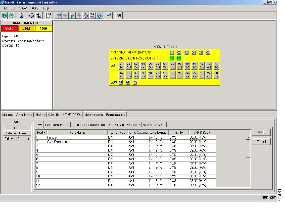
Figure 9-1 Provisioning Line Parameters on the DS-1 Ports

Step 3 Depending on the setting you need to modify, click the Line, Line Thresholds, Elect Path Thresholds, VT1.5 Path Threshold, or Alarm Behavior subtab.


Note See "Manage Alarms" for information about the Alarm Behavior subtab.


Step 4 Modify any of the settings found under these subtabs.
For definitions of the line settings, see Table 9-1. For definitions of the line threshold settings, see Table 9-2. For definitions of the electrical path settings, see Table 9-3.

For the factory default settings for the DS-1 ports, see Table C-1.

Step 5 Click Apply.

Step 6 Repeat Steps 4 and 5 for each subtab that has parameters you want to provision.

Table 9-1 describes the values on the Provisioning > Line subtab for the DS-1 ports.

Table 9-1 Line Options for DS-1 Ports  

Parameter
Description
Options

Port #

Port number

1 to 14 (XTC-14)

1 to 28 (XTC-28-3)

Port

Port name

User-defined, up to 32 alphanumeric/special characters. Blank by default

See 314 Assign a Name to a Port.

Line Type

Defines the line framing type

D4

ESF - Extended Super Frame

Unframed

Line Coding

Defines the DS-1 transmission coding type

AMI - Alternate Mark Inversion (default)

B8ZS - Bipolar 8 Zero Substitution

Line Length

Defines the distance (in feet) from backplane connection to the next termination point

0 - 131 (default)

132 - 262

263 - 393

394 - 524

525 - 655

State

Places port in service,
out of service,
out of service-maintenance, or out of service-auto in service.

IS

OOS

OOS_MT

OOS_AINS

AINS Soak

Automatic in-service soak

Duration of valid input signal in hh.mm after which the port is set in service by the software.

0 to 48 hours, 15 minutes increments.


Table 9-2 describes the values on the Provisioning > Line Thresholds subtab for the DS-1 ports.

Table 9-2 Line Thresholds Options for DS-1 Ports 

Parameter
Description
Options

Port

Port number

1 to 14 (XTC-14)

1 to 28 (XTC-28-3)

CV

Coding violations

Numeric. Can be set for 15-minute or one-day intervals. Select the bullet and click the Refresh button.

ES

Errored seconds

Numeric. Can be set for 15-minute or one-day intervals. Select the bullet and click the Refresh button.

SES

Severely errored seconds

Numeric. Can be set for 15-minute or one-day intervals. Select the bullet and click the Refresh button.

LOSS

Number of one-second intervals containing one or more loss of signal (LOS) defects

Numeric. Can be set for 15-minute or one-day intervals. Select the bullet and click the Refresh button.


Table 9-3 describes the values on the Provisioning > Elect Path Thresholds subtab for the DS-1 ports.

Table 9-3 Electrical Path Threshold Options for DS-1 Ports 

Parameter
Description
Options

Port

Port number

1 to 14 (XTC-14)

1 to 28 (XTC-28-3)

CV

Coding violations

Numeric. Can be set for 15-minute or one-day intervals. Select the bullet and click the Refresh button.

ES

Errored seconds

Numeric. Can be set for 15-minute or one-day intervals. Select the bullet and click the Refresh button.

SES

Severely errored seconds

Numeric. Can be set for 15-minute or one-day intervals. Select the bullet and click the Refresh button.

SAS

Severely errored frame/alarm indication signal

Numeric. Can be set for 15-minute or one-day intervals. Select the bullet and click the Refresh button.

AISS

Alarm indication signal seconds

Numeric. Can be set for 15-minute or one-day intervals. Select the bullet and click the Refresh button.

UAS

Unavailable seconds

Numeric. Can be set for 15-minute or one-day intervals. Select the bullet and click the Refresh button.


Table 9-4 describes the values on the Provisioning > VT1.5 Path Thresholds subtab for the DS-1 ports.

Table 9-4 VT1.5 Path Thresholds Options for DS-1 ports 

Parameter
Description
Options

Port #

DS-1 ports partitioned for STS

Read-only

Line 1, STS 1, Line 2, STS 1

Line 3, STS 1, Line 4 STS 1

CV

Coding violations

Numeric. Can be set for 15-minute or one-day intervals. Select the bullet and click the Refresh button (Near End, STS termination).

ES

Errored seconds

Numeric. Can be set for 15-minute or one-day intervals. Select the bullet and click the Refresh button (Near End, STS termination).

FC

Failure count

Numeric. Can be set for 15-minute or one-day intervals. Select the bullet and click the Refresh button (Near End, STS termination).

SES

Severely errored seconds

Numeric. Can be set for 15-minute or one-day intervals. Select the bullet and click the Refresh button (Near End, STS termination).

UAS

Unavailable seconds

Numeric. Can be set for 15-minute or one-day intervals. Select the bullet and click the Refresh button (Near End, STS termination).


Note The threshold value displays after the circuit is created.


Step 7 Return to your originating procedure (NTP).


DLP-B166 Change Line and Threshold Settings for the DS-3 Ports

Purpose

This task changes the line and threshold settings for the DS-3 ports. The default DS-3 values are listed in Table C-2.

Tools/Equipment

None

Prerequisite Procedures

60 Log into CTC

Required/As Needed

As needed

Onsite/Remote

Onsite or remote

Security Level

Provisioning or higher


Step 1 In the node view, double-click the XTC-28-3 card where you want to change the DS-3 line or threshold settings.

Step 2 Click the Provisioning tab.

Step 3 Click the DS-3 tab.

Step 4 Depending on the setting you need to modify, click the Line, Line Thresholds, STS-1 Path Threshold, or Alarm Behavior subtab.


Note See "Manage Alarms" for information about the Alarm Behavior subtab.


Step 5 Modify any of the settings found under these subtabs. For definitions of the Line settings, see Table 9-5. For definitions of the Line Threshold settings, see Table 9-6. For definitions of the SONET Threshold settings, see Table 9-7.

For the factory default settings for the DS-3 ports, see Table C-2.

Step 6 Click Apply.

Step 7 Repeat Steps 5 and 6 for each subtab that has parameters you want to provision.

Table 9-5 describes the values on the Provisioning > Line subtab for the DS-3 ports.

Table 9-5 Line Options for DS-3 Ports

Parameter
Description
Options

Port #

Port number

1 to 3

Port

Port name

User-defined, up to 32 alphanumeric/ special characters. Blank by default.
See 314 Assign a Name to a Port.

Line Length

Defines the distance (in feet) from backplane connection to the next termination point

0 - 225 (default)

226 - 450

State

Places port in service,
out of service,
out of service-maintenance, or out of service-auto in service.

IS

OOS

OOS_MT

OOS_AINS

AINS Soak

Automatic in-service soak

Time of presence of valid input signal in hh.mm after which the port is set in service by the software. 0 to 48 hours, 15 minutes increments.


Table 9-6 describes the values on the Provisioning > Line Thresholds subtab for the DS-3 ports.

Table 9-6 Line Threshold Options for DS-3 Ports  

Parameter
Description
Options

Port #

Port number

1 to 3

CV

Coding violations

Numeric. Can be set for 15-minute or one-day intervals. Select the bullet and click the Refresh button.

ES

Errored seconds

Numeric. Can be set for 15-minute or one-day intervals. Select the bullet and click the Refresh button.

SES

Severely errored seconds

Numeric. Can be set for 15-minute or one-day intervals. Select the bullet and click the Refresh button.

LOSS

Loss of signal; number of one-second intervals containing one or more LOS defects

Numeric. Can be set for 15-minute or one-day intervals. Select the bullet and click the Refresh button.


Table 9-7 describes the values on the Provisioning > STS-1 Path Threshold subtab for the DS-3 ports.

Table 9-7 STS-1 Path Threshold Options for DS-3 Ports 

Parameter
Description
Options

Port #

DS-3 ports partitioned for STS

Read-only

DS-3 ports 1 to 3

any available STS

CV

Coding violations

Numeric. Can be set for 15-minute or one-day intervals. Select the bullet and click the Refresh button (Near and Far End, STS termination only).

ES

Errored seconds

Numeric. Can be set for 15-minute or one-day intervals. Select the bullet and click the Refresh button (Near and Far End, STS termination only).

FC

Failure count

Numeric. Can be set for 15-minute or one-day intervals. Select the bullet and click the Refresh button (Near and Far End, STS termination only).

SES

Severely errored seconds

Numeric. Can be set for 15-minute or one-day intervals. Select the bullet and click the Refresh button (Near and Far End, STS termination only).

UAS

Unavailable seconds

Numeric. Can be set for 15-minute or one-day intervals. Select the bullet and click the Refresh button (Near and Far End, STS termination only).


Note The threshold value displays after the circuit is created.


Step 8 Return to your originating procedure (NTP).


NTP-B89 Modify Line Settings and PM Parameter Thresholds for Optical Ports

Purpose

This procedure changes the line and threshold settings for optical cards and ports. The default OC-N card settings are provided in the "Card Default Settings" section.

Tools/Equipment

None

Prerequisite Procedures

None

Required/As Needed

As needed

Onsite/Remote

Onsite or remote

Security Level

Provisioning or higher


Step 1 Complete the "DLP-B60 Log into CTC" task at the node where you want to change the card settings. If you are already logged in, continue with Step 2.

Step 2 Complete the "NTP-B108 Back Up the Database" procedure on page 14-6.

Step 3 Perform any of the following tasks as needed:

170 Change Line Settings for OC-N Cards

171 Change SONET Thresholds Settings for OC-N Cards

172 Change an Optical Port to SDH

Step 4 Complete the "NTP-B108 Back Up the Database" procedure on page 14-6.

Stop. You have completed this procedure.


DLP-B170 Change Line Settings for OC-N Cards

Purpose

This task changes the line settings for OC-N cards.

Tools/Equipment

None

Prerequisite Procedures

60 Log into CTC

Required/As Needed

As needed

Onsite/Remote

Onsite or remote

Security Level

Provisioning or higher


Step 1 Double-click the OC-N card where you want to change the line settings.

Step 2 Click the Provisioning > Line tabs.

Step 3 Modify any of the settings listed in Table 9-8.

See Table C-3 for OC-3 card default settings, Table C-4 for OC-12 card default settings, or Table C-5 for OC-48 card default settings.


Note The STS subtab is used to provision intermediate path performance monitoring (IPPM). To provision IPPM, circuits must be provisioned on the card.


Table 9-8 OC-N Card Line Settings 

Parameter
Description
Options

Port #

Port number (read-only)

1 to 4 (OC-3)

1 (OC-12, OC-48)

Port Name

Provides the ability to assign the specified port a name

User-defined, up to 32 alphanumeric/ special characters. Blank by default.
See 314 Assign a Name to a Port.

SF BER

Sets the signal fail bit error rate

1E-3

1E-4 (default)

1E-5

SD BER

Sets the signal degrade bit error rate

1E-5

1E-6

1E-7 (default)

1E-8

1E-9

Provides Synch

If checked, the card is provisioned as a network element timing reference

Yes (checked)

No (unchecked)

(Read-only)

EnableSync Msg

Enables synchronization status messages (S1 byte), which allow the node to choose the best timing source

Yes (checked, default)

No (unchecked)

Send DoNotUse

When checked, sends a DUS (do not use) message on the S1 byte

Yes (checked)

No (unchecked, default)

PJSTSMon #

Sets the STS that will be used for pointer justification. If set to 0, no STS is monitored. Only one STS can be monitored on each OC-N port.

0 - 3 (OC-3, per port)

0 - 12 (OC-12)

0 - 48 (OC-48)

State

Places port in service,
out of service,
out of service-maintenance, or out of service-auto in service.

IS

OOS

OOS_MT

OOS_AINS

AINS Soak

Automatic in-service soak

Duration of valid input signal in hh.mm after which the card is set in service by the software.

0 to 48 hours, 15 minutes increments.

Type

Defines the port as SONET or SDH. The Enable Sync Msg field and the Send Do Not Use field must be disabled before the port can be set to SDH.

Sonet

SDH


Step 4 Click Apply.

Step 5 Return to your originating procedure (NTP).


DLP-B171 Change SONET Thresholds Settings for OC-N Cards

Purpose

This task changes SONET thresholds settings for OC-N cards.

Tools/Equipment

None

Prerequisite Procedures

60 Log into CTC

Required/As Needed

As needed

Onsite/Remote

Onsite or remote

Security Level

Provisioning or higher


Step 1 In node view, double-click the OC-N card where you want to change the SONET thresholds settings ( Figure 9-2).

Step 2 Click the Provisioning > SONET Thresholds tabs ( Figure 9-2).

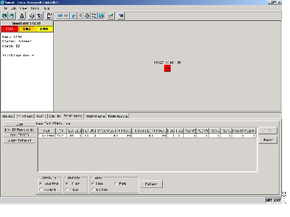
Figure 9-2 Provisioning SONET Thresholds for the OC48 IR 1310 Card

Step 3 Modify any of the settings listed in Table 9-9.

See Table C-3 for OC-3 card default settings, Table C-4 for OC-12 card default settings, or Table C-5 for OC-48 card default settings.

Table 9-9 OC-N SONET Thresholds Options 

Parameter
Description
Options
Port

Port number

1 to 4 (OC-3)

1 (OC-12, OC-48)

CV

Coding violations

Numeric. Can be set for 15-minute or one-day intervals for Line, Section, or Path (Near and Far End). Select the bullet and click the Refresh button.

ES

Errored seconds

Numeric. Can be set for 15-minute or one-day intervals for Line, Section, or Path (Near and Far End). Select the bullet and click the Refresh button.

SES

Severely errored seconds

Numeric. Can be set for 15-minute or one-day intervals for Line, Section, or Path (Near and Far End). Select the bullet and click the Refresh button.

SEFS

Severely errored framing seconds

Numeric. Can be set for 15-minute or one-day intervals for Line, Section, or Path (Near and Far End). Select the bullet and click the Refresh button.

FC

Failure count

Numeric. Can be set for 15-minute or one-day intervals for Line. Select the bullet and click the Refresh button. or Path (Near and Far End)

UAS

Unavailable seconds

Numeric. Can be set for 15-minute or one-day intervals for Line or Path (Near and Far End). Select the bullet and click the Refresh button.

PPJC-PDET

Positive Pointer Justification Count, STS Path detected.

Numeric. Can be set for 15-minute or one-day intervals for Line (Near and Far End). Select the bullet and click the Refresh button.

NPJC-PDET

Negative Pointer Justification Count, STS Path detected.

Numeric. Can be set for 15-minute or one-day intervals for Line (Near and Far End). Select the bullet and click the Refresh button.

PPJC-PGEN

Positive Pointer Justification Count, STS Path generated.

Numeric. Can be set for 15-minute or one-day intervals for Line (Near and Far End). Select the bullet and click the Refresh button.

NPJC-PGEN

Negative Pointer Justification Count, STS Path generated.

Numeric. Can be set for 15-minute or one-day intervals for Line (Near and Far End). Select the bullet and click the Refresh button.

PSC

Protection Switching Count (Line)

Numeric. Can be set for 15-minute or one-day intervals for Line (Near and Far End). Select the bullet and click the Refresh button.

PSD

Protection Switch Duration (Line)

Numeric. Can be set for 15-minute or one-day intervals for Line (Near and Far End). Select the bullet and click the Refresh button.

PSC-W

Protection Switching Count - Working line

BLSR is not supported on the OC-3 card; therefore, the PSC-W, PSC-S, and PSC-R PMs do not increment.

Numeric. Can be set for 15-minute or one-day intervals for Line (Near and Far End). Select the bullet and click the Refresh button.

PSD-W

Protection Switching Duration - Working line

BLSR is not supported on the OC-3 card; therefore, the PSD-W, PSD-S, and PSD-R PMs do not increment.

Numeric. Can be set for 15-minute or one-day intervals for Line (Near and Far End). Select the bullet and click the Refresh button.


Step 4 Click Apply.

Step 5 Return to your originating procedure (NTP).


DLP-B172 Change an Optical Port to SDH

Purpose

Use this task to provision a port on an OC-N card for SDH.

Tools/Equipment

None

Prerequisite Procedures

60 Log into CTC

Required/As Needed

As needed

Onsite/Remote

Onsite or remote

Security Level

Provisioning or higher


Step 1 Double-click the OC-N card where you want to provision a port for SDH.
Before you can change the port type to SDH, ensure the following:

The EnableSyncMsg and SendDoNotUse fields are unchecked.

The card is not part of a BLSR or 1+1 protection group.

The card is not part of an orderwire channel.

The card is not a SONET DCC termination point.

Step 2 Click the Provisioning > Line tabs.

Step 3 In the Type field, specify the port and choose SDH.

Step 4 Click Apply.

Step 5 If the card is a multiport OC-N card, such as an OC-3, you can repeat Steps 3 and 4 for any other ports on the card.

Step 6 Return to your originating procedure (NTP).


hometocprevnextglossaryfeedbacksearchhelp

Posted: Mon Feb 25 06:20:45 PST 2008
All contents are Copyright © 1992--2008 Cisco Systems, Inc. All rights reserved.
Important Notices and Privacy Statement.