|
|

Table Of Contents
5.1.1 Multiplexing Structure and Mapping modes
5.1.2 Mapping of Tributaries into VC-n
5.1.4 STM-N Regenerator and Multiplex Section Layer
5.4.3 L2 Provider Bridging functionality
5.5.4 DCC Transparency Features
5.7.1 Backup and Restoration of Configuration Data
5.7.6 Managed Object Attributes
5.8 Physical Interface Indexes
ONS 15305 Features
This chapter provides an overview of the features of the ONS 15305.
5.1 SDH Features
The ONS 15305 SDH Features are described in the following sub-sections.
5.1.1 Multiplexing Structure and Mapping modes
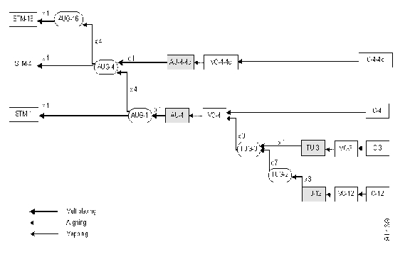
The ONS 15305 complies with the basic multiplexing principles outlined in Clause 6 in ITU-T G.707 and ETSI EN 300147 clause 4. The ONS 15305 supports the multiplexing structure outlined in Figure 5-1 This is a subset of the possible multiplexing structures defined in ITU-T G.707 clause 6 and ETSI EN 300 147 clause 4.
Figure 5-1 Multiplexing Mapping Structure
The ONS 15305 complies with the multiplexing methods outlined in clause 7 in ITU-T G.707 and ETSI EN 300 147 clause 5 for the supported multiplexing structures.
5.1.2 Mapping of Tributaries into VC-n
This section describes supported mapping of tributaries into VC-n.
5.1.2.1 Asynchronous Mapping of 44 736 kbps
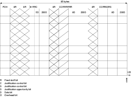
The ONS 15305 supports asynchronous mapping of 44 736 Kbps signal into a VC-3 container as shown in Figure 5-2. The mapping is in accordance to ITU-T G.707 clause 10.1.2.1 and ETSI EN 300 147 Clause 8.
Figure 5-2 Asynchronous Mapping of 44 736 kbps Tributary into VC-3
5.1.2.2 Asynchronous Mapping of 34 368 kbps
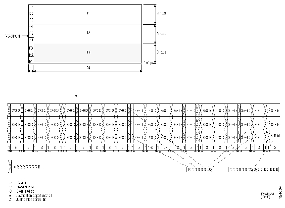
The ONS 15305 supports asynchronous mapping of 34 368 kbps signal into a VC-3 container as shown in Figure 5-3. The mapping is in accordance to ITU-T G.707 clause 10.1.2.2 and ETSI EN 300 147 Clause 8.
Figure 5-3 Asynchronous Mapping of 34 368 kbps Tributary into VC-3
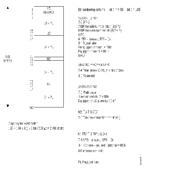
5.1.2.3 Asynchronous mapping of 2048kbps
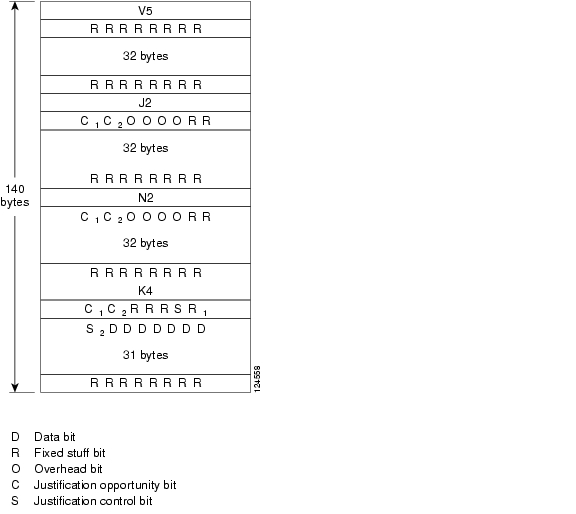
The ONS 15305 supports asynchronous mapping of 2048kbps signal into a VC-12 container as shown in Figure 5-4. The mapping is in accordance to ITU-T G.707 clause 10.1.4.1 and ETSI EN 300 147 Clause 8.
Figure 5-4 Asynchronous Mapping 2048 kbps Tributary into VC-12
5.1.2.4 Mapping of GFP frames
The ONS 15305 supports the Generic Framing Procedure (GFP) to encapsulate variable length payload of various client signals for subsequent transport over SDH networks as defined in ITU-T G.707. The ONS 15305 supports mapping of a GFP frame stream into a Container-n (n=12,3,4 or 12/3/4-Xv). The mapping is in accordance to ITU-T G.707 clause 10.6.
5.1.2.5 Proprietary mapping of HDLC encapsulated Ethernet frames
The ONS 15305 provides a proprietary mapping scheme for mapping of HDLC encapsulated Ethernet frames traffic into VC-12 containers. The proprietary mapping scheme used to map the data into a VC-12 container is described in Figure 5-5.
Figure 5-5
Proprietary mapping of HDLC frames
5.1.3 STM-N Physical Layer
The ONS 15305 offers the following physical interfaces:
•
Optical STM-1 interfaces, S1.1, L1.1, L1.2
•
•
The ONS 15305 implements the supported Physical layer functions in accordance to ITU-T G.783 clause 9.
5.1.4 STM-N Regenerator and Multiplex Section Layer
The ONS 15305 implements the STM-N (n=1,4 and16) Regenerator and Multiplex Section layer functions in accordance to ITU-T G.783 clause 10 and 11.
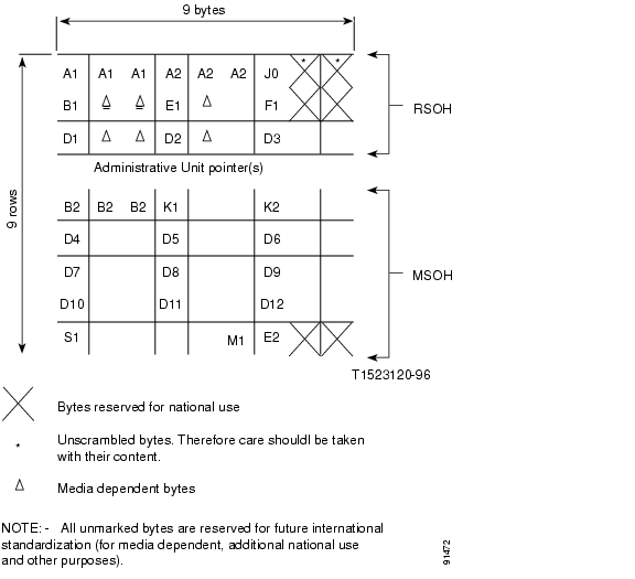
5.1.4.1 SOH Implementation
The ONS 15305 complies with the SOH implementation methods outlined in clause 9 in ITU-T G.707 and ETSI EN 300 147 clause 7. The assignment of the STM-n SOH is outlined in Figure 5-6.
Figure 5-6 STM-n Section Overhead (SOH)
Note
5.1.5 VC-n/m Path layer
The ONS 15305 offers the support of the following payloads:
•
•
•
•
•
•
•
The support of the VC-4-4c contiguous concatenation and the support of the VC-12/3/4-Xv virtual concatenation are described in Concatenation Schemes.
The ONS 15305 implements the supported Path layer functions in accordance to ITU-T G.783 clause 12 for VC-n, where n=4-X, 4, 3-X, 3.
The ONS 15305 implements the supported Path layer functions in accordance to ITU-T G.783 clause 13 for VC-m, where m=12-X, 12.
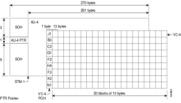
5.1.5.1 VC-4-Xc/VC-4/VC-3 POH Implementation
The ONS 15305 complies with the POH implementation methods outlined in clause 9 in ITU-T G.707 and ETSI EN 300 147 clause 7. The assignment of the VC-4 POH is outlined in Figure 5-7
The ONS 15305 supports all the VC-4-Xc/VC-4/VC-3 POH bytes as described in ITU-T G.707 Clause 9.3.1, with the following exceptions:
•
•
•
•
Figure 5-7 VC-4 POH
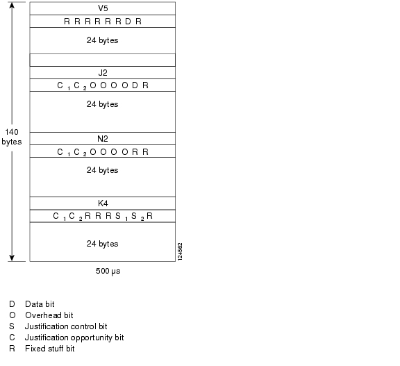
5.1.5.2 VC-2/VC-1 POH implementation
The ONS 15305 complies with the POH implementation methods outlined in clause 9 in ITU-T G.707 and ETSI EN 300 147 clause 7.
The assignment of the VC-12 POH is outlined in Figure 5-8.Figure 5-8 VC-12 POH
The ONS 15305 supports all the VC-2/VC-1 POH bytes as described in ITU-T G.707 Clause 9.3.1, with the following exceptions:
•
•
5.1.6 Cross-Connect
The ONS 15305 implements a full non-blocking 64x64 STM1 cross connect with VC12, VC-3 and VC-4 granularity.
The following cross connect types are supported:
•
•
5.1.7 Concatenation Schemes
This section describes supported Concatenation Schemes.
5.1.7.1 Contiguous Concatenation
The ONS 15305 supports standard contiguous concatenation at VC-4-4c level. The ONS 15305 implements the supported VC-4-4c in accordance to ITU-T G.707 clause 11.1 and ETSI EN 300 147 Clause 9.
The support for the standard concatenation schemes includes the following features:
•
•
•
The following modules supports contiguous concatenation:
•
•
5.1.7.2 Virtual Concatenation
The ONS 15305 supports virtual concatenation and the following VC-n-Xv are supported:
•
•
•
Table 5-1 Number of members the VCAT Bundles
VC12
50
N/A
Maximum per Vcggroup
VC3
3
21
Maximum per Vcggroup
VC4
1
7
Maximum per Vcggroup
Number of members the VCAT bundles can include (1-7) is found in Table 5-1.
The ONS 15305 implements the supported VC-4-Xv and VC-3-Xv functionality in accordance to ITU-T G.707 clause 11.2 and ETSI EN 300 147 Clause 9. The ONS 15305 implements the supported VC-12-Xv functionality in accordance to ITU-T G.707 clause 11.4 and ETSI EN 300 147 Clause 9.
Virtual concatenation is supported in conjunction with EOS mapping and is module dependent. The EOS mapping is described in Ethernet over SDH mapping.
5.1.8 Protection
As shown in Figure 5-9, ONS 15305 offers the following different protection schemes:
•
•
Figure 5-9
Protection Scheme for the ONS 15305
5.1.8.1 1+1 Linear MSP
The ONS 15305 offers 1+1 linear Multiplex Section Protection (MSP) on all optical STM-N interfaces.
The following rules applies for the 1+1 MSP protection:
•
•
The 1+1 MSP functionality is in accordance with ITU-T G.841, clause 7.1. The following parameters are configurable on an MSP object:
•
•
•
•
The protocol used for K1 and K2 (b1-b5) is defined in ITU-T G.841, clause 7.1.4.5.1. The protocol used is 1+1 bi-directional switching compatible with 1:n bi-directional switching.
5.1.8.2 SNC Protection
The ONS 15305 supports two types of SNC protection, SNC/I (Sub Network Connection protection with Inherent monitoring) and SNC/N (Sub Network Connection protection with non-intrusive monitoring).
SNC is supported for the following objects:
•
•
•
•
The SNC P functionality is in accordance with ITU-T G.841 Clause 8. The following parameters are configurable on an SNC object:
•
•
•
•
The Application architecture supported is 1+1 unidirectional switching, according to ITU-T G.841 clause 8.3.2. The switch initiation criteria are implemented as described in ITU-T G.841 clause 8.4.
The protection algorithm is implemented according to ITU-T G.841 clause 8.6.
5.1.8.2.1 SNC Protected Uni-directional Cross-Connection - Limitations
When one direction of a path forms part of an SNC protected uni-directional cross-connection, the other direction can not form part of a different SNC protected uni-directional cross-connection. But the two directions can form part of two different uni-directional un-protected cross connections. This applies to uni-directional cross-connections on all path layers.
Example:
Suppose the uni-directional VC-12 cross-connection from 1/1/1.1.1.1.1 (input) to 1/2/1.1.1.1.1 (output) is SNC protected by 1/3/1.1.1.1.1 (input). In this case, the output direction of 1/1/1.1.1.1.1 and 1/3/1.1.1.1.1, and the input direction of 1/2/1.1.1.1.1 are un-used. However, due to the above mentioned limitation, they can not be part of a new SNC protected unidirectional cross-connection, e.g. from 1/2/1.1.1.1.1 (input) to 1/1/1.1.1.1.1 (output) protected by 1/14/1.1.1.1.1. They may however form part of un-protected uni-directional cross-connections.
5.1.9 Performance Monitoring
In the subsequent chapters the following definition are used, according to G.826:
•
•
•
•
5.1.9.1 Regenerator and Multiplex Section Performance Monitoring
ONS 15305 offers full performance monitoring on regenerator and multiplex sections according to G.829.
The following parameters are calculated:
•
•
•
•
For the regenerator section near end data are presented, for the multiplex section both near end and far end data are presented.
The available time periods are:
•
•
The system presents current data and historical data, the number of time periods are:
•
•
ONS 15305 calculates excessive error and degrade signal defects assuming Poisson distribution of errors, according to ITU-T G.826.
The excessive error defect (dEXC) is detected if the equivalent BER exceeds a pre-set threshold of 10E-5, and be cleared if the equivalent BER is better than 10E-6, according to ITU-T G.806.
The degraded signal defect (dDEG) is detected if the equivalent BER exceeds a pre-set threshold of 10E-X, where x=6, 7, 8 or 9. The dDEG is cleared if the equivalent BER is better than 10E-(X+1), according to ITU-T G.806.The threshold is individual configurable for the regenerator and multiplex section, from 10E-6 to 10E-9.
5.1.9.2 Path Performance Monitoring
ONS 15305 offers full performance monitoring on the SDH path level according to G.828, the following objects are supported:
•
•
•
•
The following parameters are calculated:
•
•
•
•
Both near end and far end data are presented.
The available time periods are:
•
•
The system presents current data and historical data, the number of time periods are:
•
•
ONS 15305 calculates excessive error and degrade signal defects assuming Poisson distribution of errors, according to ITU-T G.826.
The excessive error defect (dEXC) is detected if the equivalent BER exceeds a pre-set threshold of 10E-5, and be cleared if the equivalent BER is better than 10E-6, according to ITU-T G.806.
The degraded signal defect (dDEG) is detected if the equivalent BER exceeds a pre-set threshold of 10E-X, where x=6, 7, 8 or 9. The dDEG is cleared if the equivalent BER is better than 10E-(X+1), according to ITU-T G.806.The threshold is individual configurable for the different objects, from 10E-6 to 10E-9.
5.1.9.3 Intermediate Path Performance Monitoring (IPPM)
ONS 15305 supports IPPM (Intermediate Path Performance monitoring) functions on the following objects:
•
•
•
•
The functionality is used to monitor relayed cross connects in the system, the functionality is specially useful for debugging of errored paths, to determine which section that is causing the problem. The functionality is also used to monitor paths crossing operator boarders.
The functionality is supported by use of the non-intrusive monitor points used by the SNCP process. A probe is placed on the selected object, and the performance monitoring is then automatically turned on.
The following parameters are calculated:
•
•
•
•
Both near end and far end data are presented. The available time periods are:
•
•
The system presents current data and historical data, the number of time periods are:
•
•
ONS 15305 calculates excessive error and degrade signal defects assuming Poisson distribution of errors, according to ITU-T G.826.
The excessive error defect (dEXC) is detected if the equivalent BER exceeds a pre-set threshold of 10E-5, and be cleared if the equivalent BER is better than 10E-6, according to ITU-T G.806.
The degraded signal defect (dDEG) is detected if the equivalent BER exceeds a pre-set threshold of 10E-X, where x=6, 7, 8 or 9. The dDEG is cleared if the equivalent BER is better than 10E-(X+1), according to ITU-T G.806.The threshold is individual configurable for the different objects, from 10E-6 to 10E-9.
The number of simultaneously probes supported in the system are 63.
5.1.9.4 SNC Performance Parameters
ONS 15305 implements the following SNC Performance Parameters:
•
•
•
PSC is incremented automatically each time a switch occurs. PSD and Measured Time are updated once each second. PSD is only meaningful for revertive mode.
The parameters are cleared when the protection instance is disabled or if a "ClearAllPmData" command is issued from the operator.
5.1.9.5 MSP 1+1 Parameters
ONS 15305 implements the following MSP 1+1 Performance Parameters:
•
•
•
PSC is incremented automatically each time a switch occurs. PSD and Measured Time are updated once each second. PSD is only meaningful for revertive mode.
The parameters are cleared when the protection instance is disabled or if a "ClearAllPmData" command is issued from the operator.
5.1.9.6 Pointer Justification Performance Parameters
ONS 15305 offers pointer justification performance parameters, PJE for the following objects:
•
•
PJE, both positive and negative justifications, are counted and measured over a 24 hour interval. Both current and past 24hour interval counters are available.
In addition to the PJE counters an alarm is raised if the number of PJE's over a 15minute period is greater than a configurable number, PJEL (Pointer Justification Event Limit). The PJEL is configurable from 1 to 1024 events.
5.1.10 Synchronization
ONS 15305 offers synchronization from a range of different interfaces.
In addition to the module interfaces it is possible to synchronize from a 2MHz synchronization input source on the controller module. The interface is according to ITU-T G.703. The ONS 15305 also offers a synchronization output port in the same connector, according to ITU-T G703.
The different interfaces allowed for synchronization are listed below.
Synchronization sources:
•
•
•
•
•
Through the SETS (Synchronous Equipment Timing Source), the synchronization signals are distributed to the equipment ports.
ONS 15305 offers a list of 5 possible synchronization sources for the T0, selection of the sync source is based upon the quality level.
ONS 15305 supports SSM messaging on the STM-N interfaces, this is not supported on the E1 interface.
5.2 Ethernet over SDH mapping
ONS 15305 supports two different modes of Ethernet over SDH (EOS) mapping:
1.
2.
The support of the different EOS modes is module dependent.
The following modules are Proprietary mapping:
•
•
The following modules are GFP-F mapping:
•
•
5.2.1 Proprietary Mapping
ONS 15305 provides a proprietary mapping scheme for mapping of Ethernet traffic into a number of VC-12 containers.
The HDLC encapsulated Ethernet frames are mapped into a number of VC-12 containers in a round-robin fashion with an inverse multiplexer function. The mapping process is described in Proprietary mapping of HDLC encapsulated Ethernet frames.
A total differential delay of up to 8ms is supported.
The total bandwidth for one WAN channel is 100 Mbps or 50xVC-12 containers. The Proprietary VC-12 mapping scheme for Ethernet take advantage of 2,16 Mbps in each VC-12, which means that 47xVC-12 are sufficient to transport 100MbpsEhernet.
The VC-12 k.l.m reference assignment for the Ethernet WAN port is fully flexible, and controlled in the same way as a VC-12 cross connect.
The sequence number attached to each VC-12 is used for alarm indication only in case of a sequence mismatch, the sequence number is not used for reordering of the incoming VC-12's. The order of VC's carrying Ethernet traffic between two WAN-ports therefore needs to be obtained.
In case of a failure on one of the VC-12s, the effected VC-12 is removed from the channel, allowing the traffic to flow on the remaining VC-12 connections. RDI is used to indicate a failure to the remote side.
5.2.2 Standardized Mapping
ONS 15305 supports standardized ways of mapping Ethernet over SDH. The mapping schemes include mapping protocol, concatenation scheme and control protocols.
5.2.2.1 GFP
ONS 15305 supports framed mapped GFP (GFP-F) according to ITU-T 7041.The GFP implementation supports the following functions:
•
•
•
•
•
•
•
The mapping of GFP frames in VC-x containers are described in Mapping of GFP frames.
5.2.2.1.1 GFP Alarm and Event Conditions
The GFP implementation supports the following alarm and event conditions:
•
•
–
•
–
•
–
•
–
5.2.2.1.2 GFP Performance Monitoring
The GFP implementation collects the following performance parameters:
•
•
•
•
•
•
•
•
A degrade alarm is available for the following performance parameters:
•
•
The degrade alarms are handled in a similar way as the SDH degrade alarms.
5.2.2.2 Virtual Concatenation (VCAT) and Link Capacity Adjustment Scheme (LCAS)
ONS 15305 supports virtual concatenation according to ITU-T 707, the support of VCAT is dependent on module type. The VCAT implementation supports the following functions:
•
–
–
–
•
–
–
The VC-x level is individually configurable pr. mapper port, a mix of different VC-x levels in one VCG group is not allowed.
A total differential delay of up to 62ms is supported for the different VCG groups.
ONS 15305 supports the LCAS protocol in conjunction with VCAT as defined in ITU-T 7042. The LCAS protocol implemented covers the following functions:
•
•
•
•
•
5.2.2.2.1 VCAT and LCAS Configuration Modes
The ONS 15305 offers two different operation modes for the VCAT and LCAS functionality, the two modes are:
1.
2.
5.2.2.2.2 VCAT with LCAS enabled
VCAT with LCAS enabled is always uni-directional, which enables the possibility to have different capacity in each direction, but requires a separate cross connect/capacity setup in each direction.
5.2.2.2.3 VCAT without LCAS enabled
When VCAT is used without LCAS, there is no mechanism for removing of a faulty VC container in a VCG group. To solve this problem the ONS 15305 implements, in addition to the standard mode, a proprietary mode.
The following configurations are available:
•
•
If SoftLCAS-bidirectional mode is enabled, the cross connections are not uni-directional, but bi-directional. In addition RDI signalling is enabled. A faulty container in a VCG group is removed based upon the VC alarm condition or based upon RDI signalling (similar to proprietary mapping). This will allow a VCG group to continue operation even if the VCG has a failed member. This configuration mode is proprietary.
5.2.2.2.4 VCAT and LCAS Alarm and Event Conditions
Alarms related to the VCAT and LCAS reported by default are shown in Table 5-2.
In addition to the default alarms in Table 5-2, the optional alarms shown in Table 5-3 are available if enabled from the Cisco EdgeCraft.
5.3 PDH Features
The ONS 15305 PDH features are described in the following sub-sections.
5.3.1 E1 features
ONS 15305 supports a number of E1 interfaces that are mapped into SDH VC-12 containers. The SDH mapping features is described SDH Features.
Different E1 tributary modules are available supporting 8, 21 or 63 E1 interfaces.
The E1 interfaces provides a number of different services:
•
•
•
It is possible to configure the E1 interfaces individually to support the different services.
5.3.1.1 Transparent Leased Line
The transparent or unstructured leased line service delivers a full digital bit rate of 2048 kbps with no restriction on the binary content.
The service is symmetrical in both directions and only supports point-to-point connections. The service is specified in EN 300 247 and the network interface is specified in EN 300 418.
An alarm indication signal (AIS) is inserted toward the network if loss of signal (LOS) is detected from the customer.
AIS is also inserted towards the customer if LOS or other major alarms are detected from the networks.
5.3.1.2 ISDN Primary Rate Access
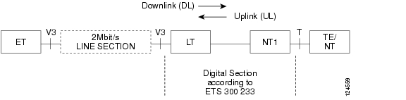
ISDN Primary rate access (PRA) is used to provide ISDN access for the end customers of an operator. A block diagram describing the digital line section for PRA is shown in Figure 5-10.
Figure 5-10 Digital Line Section for PRA - Block Diagram
–
–
–
–
–
–
If a 2 Mbps Line Section is inserted between LT and ET,
the interface at the ET side is named V3The interfaces related to the transmission between LT and NT1 are not specified, nor the transmission medium.
•
•
The ET is responsible for management of the PRA access section. This is embedded in the functional specification of interface V3 comprising uplink reporting of failure conditions and detected bit errors, and downlink provision of loop back commands.
The LT does not any function related to supervision of transmission quality. Note that no LT1 functionality is implemented in ONS 15305.
The NT1 performs the following functions related to supervision of transmission quality:
•
•
•
•
•
Loopback point 2 in the NT1 is specified towards the ET. Loopback commands are given from the ET by codes in TS0 bit Sa6.
5.3.1.3 ISDN PRA with Fixed Timing
When an E1 is configured in ISDN PRA with fixed timing, a slip buffer is implemented in the receiver direction. The E1 output signal is clocked with the internal T0 timing reference, providing the network timing to the E1 interface. A slip buffer is used to adapt to phase changes in the E1.
5.3.2 E3/T3 features
ONS 15305 supports a number of E3/T3 interfaces that is mapped into SDH VC-3 containers. The SDH mapping features is described in SDH Features.
Different E3/T3 tributary modules are available supporting 3 or 6 E1 interfaces.
The E3/T3 interfaces provides a number of different services as shown below:
•
•
It is possible to configure the E3/T3 interfaces individually to support the different services.
5.3.2.1 E3 transparent Leased Line
The transparent or unstructured leased line service delivers a full digital bit rate of 34.368 Mbps with no restriction on the binary content. The service is symmetrical in both directions and only supports point-to-point connections. An alarm indication signal (AIS) is inserted toward the network if loss of signal (LOS) is detected from the customer. AIS is also inserted towards the customer if LOS or other major alarms are detected from the networks.
5.3.2.2 T3 transparent Leased Line
The transparent or unstructured leased line service delivers a full digital bit rate of 44.736 Mbps with no restriction on the binary content. The service is symmetrical in both directions and only supports point-to-point connections. An alarm indication signal (AIS) is inserted toward the network if loss of signal (LOS) is detected from the customer. AIS is also inserted towards the customer if LOS or other major alarms are detected from the networks.
5.3.3 Loopbacks
Two types of loopbacks are supported for the interface; Customer Loop (LL3) and Network loop (LL2).
A customer loop takes the incoming customer traffic and sends it back towards the customer. Note that AIS is sent towards the network.
A network loop takes the incoming traffic from the network and sends it back towards the network. Note that in this case AIS is sent towards the customer.
The loops can be activated from the Cisco EdgeCraft terminal. For E1 tributary configured in ISDN PRA mode, loopbacks are set in-band.
5.4 IP Features
The ONS 15305 supports Ethernet L1, L2 bridging and L2 Provider Bridging Functionality.
The Ethernet L1 functionality is supported dependent on equipped module type(s) and the port configuration. See individual module descriptions;
Octal LAN 10/100Base-TX Module with Mapper, E100-WAN-8, page 21-1 and
Octal LAN 10/100Base-TX Module with Mapper, E100-WAN-8, page 21-1.Any modules, which have Ethernet LAN- or WAN-ports, supports L2 bridging.
The bridging and routing functionality is described in the subsequent chapters.
The maximum number of bridging/routing ports supported in the system s 64, which means up to 16 ports pr module slot. The number of ports pr slot is dependent of the module type. The following ports are supported:
•
•
•
•
The filtering rate of the bridge is able to operate with at full wire speed (Up to 1 Gbit/s). The forwarding rate is only be limited by the forwarding interface speed.
5.4.1 Ethernet L1
The Ethernet L1 is Ethernet mapped over SDH, with the mapping types described in Ethernet over SDH mapping. The functionality supported on a LAN port configured to L1 mode is:
•
(N/A for Optical Gigabit Ethernet modules)•
•
•
•
•
•
–
–
•
–
The Q in Q/VLAN tunnelling and Protocol tunnelling features are described in more detail in
L2 Provider Bridging functionality. The reason for offering such features on a Ethernet L1 connections is related to the possibility of interconnection of Ethernet L1 and L2 connections, a typically scenario would be grooming of several L1 connections in an ONS 15305 offering L2 functionality.5.4.2 L2 Bridging
The bridge is a transparent multi-port remote Ethernet bridge as specified in IEEE 802.3. The ONS 15305 supports standard bridging functionality, in addition it also supports provider bridge functionality. All modules/ports support standard bridging functionality, the following modules only support the provider bridge functionality:
•
•
The standard bridging functionality include the following features:
•
•
•
•
•
(N/A for Optical Gigabit Ethernet modules)•
•
•
•
•
•
•
•
•
•
•
•
•
•
The filtering rate of the bridge is able to operate at full wire speed. For FE modules the maximum pps is 148 kpps for 64 byte packet size. The forwarding rate on GE connections will be limited in case of just small packets. For GE this pps is 70% of wirespeed on small packet sizes. I.e. 1015 k at 64 bytes packet size wirespeed from 100 bytes packets 1008 kpps.
5.4.2.1 VLAN acc. to IEEE802.1Q
By default software configuration, the ONS 15305 support 802.1Q and can handle up to 4000 VLAN simultaneously. The VLAN ID range available in this case is 1-4000.
If you need to enable multicast configuration (and IGMPsnooping) on the device the maximum number of potential VLAN's must be reduced to a number lower than 4000. Each multicast group entry reduces the maximum number of VLAN's by one (1).
Note
5.4.3 L2 Provider Bridging functionality
In addition to the standard L2 functionality the following Provider Bridge functionality is supported on the specific modules listed in L2 Bridging.
•
–
•
–
The offering of Q in Q/VLAN tunnelling and protocol tunnelling enables the user to offer transparent Ethernet services in a L2 network with guaranteed security, also called L2 VPN's. The functionality is enabled at the ingress and egress ports in the network, and therefore only supported on LAN ports in the ONS 15305. The functionality is individually configurable on a pr. port basis.
The Ethertype used for the Tag insertion is the configured system Ethertype, default 0x8100.
When Tag insertion/removal is configured on a LAN port in L2 mode, only one VLAN can be configured for each port.
5.4.4 BootP Client
BootP Client is an option to automatically get an IP address and configuration-file from a BootP server during power up.
5.5 DCN Features
This chapter presents the ONS 15305 protocol stack, interfaces and communication functions used for management communications.
In this context the term DCN (Data Communication Network) is used to denote the network that transports management information between a management station and the NE. This definition of DCN is sometimes referred to as MCN (Management Communication Network). The DCN is usually physically or logically separated from the customer network.
The ONS 15305 management solution is based on SNMP over IP. The main purpose of the DCN implementation is to provide connectivity to the SNMP Agent inside the ONS 15305 via different DCN topologies. The DCN implementation however, also support transport of management traffic between other Cisco or third party nodes.
For the "IP In-band" L2 topology IP-In-band DCN, the management traffic is switched/routed between LAN/WAN ports. When IP-addressing a VLAN IF (id 100000-104000) the management connectivity is obtained at wire-speed along with the user traffic or on a separate WAN-port dedicated for management.
For all other cases, the following applies: The DCN traffic is always routed (IP) between the management interfaces. Two different router modes are available for management connectivity. One shall operate for "Numbered mode" and the second shall operate in "Un-numbered mode". Both routers shall not be accessible for DCN purpose simultaneously, and a system mode is introduced to enable desired router.
Most topologies in the following sections assume standard numbered IP interfaces, i.e. every interface (IF) connected to the router takes an IP address and a subnet. However the feature called "IP Unnumbered Interfaces" introduced in Release 2.0 will simplify planning, supervision and configuration since one IP address per network element within the same subnet shall be sufficient.
5.5.1 Management Interfaces
The purpose of the Management DCN is to carry management traffic between a management system and the managed devices. The management traffic pertinent to the ONS 15305 is IP carrying SNMP, TELNET and TFTP application protocols. In order to support management connectivity in any possible topology and application, the ONS 15305 supports management traffic on the interfaces in this section.
5.5.1.1 Management port
The ONS 15305 has a dedicated Ethernet port for management, called the "Management Port". This port can be used for local management, e.g. connecting a craft terminal. It can also be used for connecting to a separate external management network. The management port can be turned off to avoid unauthorized local access. The management port cannot be member of a VLAN.
5.5.1.2 LAN ports
The LAN ports are FE or GE Ethernet ports used for connecting customer IP traffic to the ONS 15305. LAN-ports connected to the switch (L2-mode) can be used to carry management traffic.
5.5.1.3 WAN ports
The WAN ports are device internal FE or GE Ethernet ports that can be mapped into one or more virtual containers of an SDH STM-n signal. WAN-ports can carry management traffic both in L1-and L2-mode.
5.5.1.4 DCC channels
The SDH architecture defines data communication channels (DCC) for transport of management traffic in the regenerator section (DCCR - 192 kbit/s) and in the multiplexer section (DCCM - 576 kbit/s).
Each SDH-module may terminate up to 8 DCCR and/or 4 DCCM channels, i.e. an absolute upper limitation on the number of active DCC-channels is 48. For one SDH-port, both DCC channels may be active simultaneously. Activation/deactivation of DCC channels are configurable on a per port basis.
5.5.1.5 Local VT-100 serial port
CLI for basic set-up of the ONS 15305. Can also be accessed via TELNET.
Also this RS-232 interface is regarded as a management interface, although it does not relate to the various DCN topologies described throughout the rest of this section. Only a few basic CLI-commands are provided via this interface.
5.5.2 Communication Features
The ONS 15305 Communication features are described in the following sub-sections.
5.5.2.1 IP-Forwarding
The IP-Forwarding implies that the device can have multiple IP interfaces, i.e. it can be a multi-homed IP host. In addition it is able to perform forwarding of IP datagrams between the interfaces, and the routing protocols (RIP, OSPF) are available. IP-Forwarding is software based and low capacity and is intended for management traffic only.
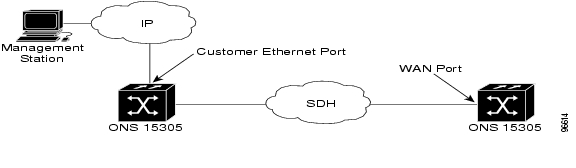
5.5.2.2 External DCN
"External DCN" means that the management station connects to the ONS 15305 via a separate DCN. The physical connection to the ONS 15305 is the Management Port.
IP/Ethernet is supported. The ONS 15305 may also serve as a gateway from an External DCN to other Cisco-nodes in the SDH network, i.e. the External DCN topology may be combined with other topologies described in the next subsections.
The direct connection of a Cisco EdgeCraft terminal to the Management Port may be regarded as a special case of the External DCN topology.
Example of the configuration is shown by Figure 5-11.
Figure 5-11 External DCN - Network Configuration
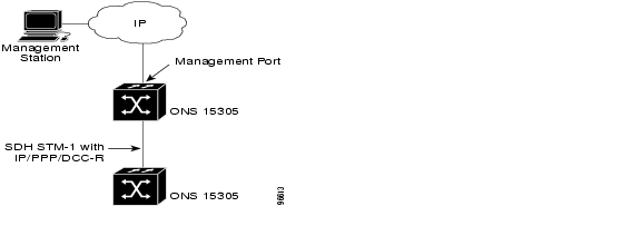
5.5.2.3 IP-In-band DCN
The configuration is described by Figure 5-12.
Figure 5-12 IP-In-band DCN - Network Configuration
"IP-In-band" means that LAN and WAN ports are carrying management traffic together with customer traffic. This is useful in topologies where (parts of) the SDH-network is owned by a different operator that does not allow a third party to use the DCC capacity.
With IP-In-band it is possible to build tunnels between "islands" that have other DCN solutions. This feature has different restrictions and options depending on whether the ports are in L1-or L2 mode:
5.5.2.3.1 L2 Mode:
A LAN- and WAN-port in L2 mode is connected to the switch. Such ports may carry in-band management traffic if an IP-address is assigned to it, or to the VLAN it belongs to. This solution is equivalent to the previous versions of ONS 15305. It is possible to split management traffic from user traffic by assigning dedicated LAN/WAN ports to management traffic.
5.5.2.3.2 L1 Mode:
In ONS 15305 R2.0 LAN- and WAN-ports can also be in L1-mode in order to support Ethernet L1 services. In this case the ports are not connected to the switch.
WAN-ports in L1-mode can carry in-band management traffic. The management traffic in such WAN-ports is identified by means of a proprietary MAC-address and can only be used over point-to-point links between Cisco nodes. This feature can be enabled or disabled per L1 WAN port.
From a system point of view this feature is similar to PPP/DCC case (See PPP/DCC DCN (IP over PPP)).
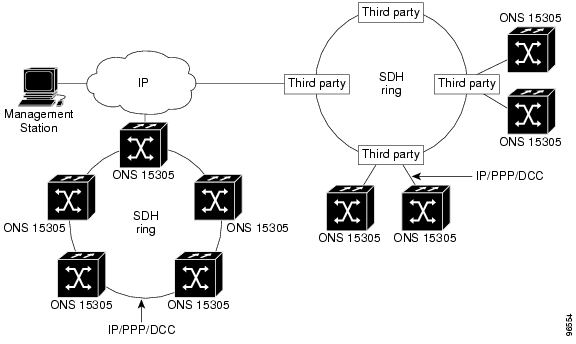
5.5.2.4 PPP/DCC DCN (IP over PPP)
PPP/DCC means that the management IP-traffic is carried in PPP over the SDH DCC channels according to NSIF-DN-0101-001. The PPP implementation supports RFC1661 (PPP), RFC1662 (PPP in HDLC-like framing) and RFC1332 (IPCP). The configuration is described by Figure 5-13.
Each PPP/DCC channel connects to the IP router individually. Normally this would take one IP subnet per DCC-link, and this is how previous versions of ONS 15305 implementations would behave. However, from ONS 15305 R2.0 on a more comprehensive PPP/DCC strategy is supported. This strategy is based on the feature called "IP Unnumbered Interfaces", and the rest of this section assumes this option.
The IP Unnumbered concept allows the system to provide IP processing on a serial interface or in general a point-to-point without assigning it an explicit IP address. The IP unnumbered interface borrows the IP address of another interface already configured on the system/router (i.e. the Management Port), thereby conserving network and address space, and making the system easier to configure, manage and maintain.
With IP Unnumbered, all nodes connected via PPP-links may be on the same IP subnet. An essential part of the implementation is the DCN ARP Proxy Agent, which makes sure that connectivity between the nodes is obtained without having to provision static routes. The Proxy Agent builds entries for all the DCN IP destinations, and will reply to ARP requests on behalf of them.
"IP Unnumbered" is regarded as a main mode, and cannot be combined with other modes that require numbered interfaces. This implies that this PPP/DCC option cannot be combined with L2 IP In-band.
Figure 5-13 PPP/DCC DCN - Example of Network Configuration
5.5.2.5 Compatibility Issues
ONS 15305 R2.0 is able to provide DCN connectivity with all ONS 15305 and ONS 15302 devices already deployed, including the installed base of ONS 15305 devices with an earlier software revision. Hence, two additional DCN options are supported; PPP/DCC for numbered interfaces and proprietary IP/DCC communication. Both M-DCC and R-DCC are configurable with CRC-16 or CRC-32.
5.5.2.5.1 PPP/DCC((IP over PPP)
ONS 15305 support PPP/DCC also on numbered interfaces. This option cannot co-exist with the IP unnumbered version of PPP/DCC as described in PPP/DCC DCN (IP over PPP). However, the numbered variant of PPP/DCC has the advantage that it can be used in combination with all other DCN modes.
5.5.2.5.2 IP/DCC(IP over HDLC)
IP/DCC is a non-standard mechanism used for conveying management information on the SDH DCC channels in a network with ONS 15305 and ONS 15302 devices only. This mechanism can be used together with the IP/DCC-Broadcast mechanism of other ONS 15305 and ONS 15302 devices emulating a shared medium on the SDH DCC channel. The IP datagrams are encapsulated in HDLC frames before they are sent out on the SDH DCC.
This configuration is applicable for a user having a subnet of ONS 15305 and ONS 15302 devices (with the ONS 15305 in the centre) and an IP based DCN connected to the ONS 15305 (e.g. the management port). The configuration is described by Figure 5-14.
The IP/DCC option has two special restrictions, imposed by the proprietary pseudo-broadcast mechanism:
•
•
Figure 5-14
IP/DCC - Network Configuration
5.5.3 Management Security
The following security features applies to management communications:
5.5.3.1 CLI Access Control
ONSCLI is by default a superuser and can block all remote SNMP users by changing the access rights and passwords.Changing CLI passwords is only possible in ONSCLI.
Locally through VT100: User name and Password mechanisms
Remotely Telnet: Telnet password and additionally same mechanisms as through VT100.
5.5.3.2 SNMPv1 Access Control
For each user (SNMP Community), the following can be configured:
•
•
5.5.3.3 SNMP Manager Identity
This is an enhancement of the SNMPv1 Community feature. Here, the SNMP manager's IP address must be configured in the device subject to management. Only legal combinations of community name and source IP address in SNMP requests are accepted.
5.5.3.4 SNMP Read/Write Control
The access rights of the registered management systems can be set to super, read/write or read only.
5.5.3.5 VLAN (802.1Q)
This security mechanism relates to the IP in-band option only: By configuring a separate VLAN for the management traffic and assigning an IP address to it, the end-users will not be able to access the device or generate traffic into the management VLAN.
5.5.3.6 Management Port Control
The Management Port can be enabled/ disabled. This gives the operator control of the local access.
5.5.4 DCC Transparency Features
This section presents the DCC Transparency feature supported by ONS 15305 and provides a description of applications.
5.5.4.1 General description
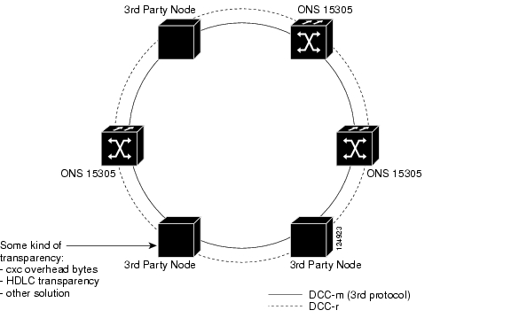
To overcome 3rd party vendors proprietary or not commonly used protocols for management connectivity, ONS 15305 has the ability to transparently forward the management signals through our nodes. This feature will can typically be used when our nodes are supposed to fit into existing ring- configurations. It may also relieve heavily loaded data communications channels (D1- D3 or D4- D12) in the network and instead let the existing signals pass through our nodes and take advantage of the potentially second channel for ONS 15305 and ONS 15302 devices utilization. In this case it is required that the existing nodes transparently pass through our signals.
5.5.4.2 Functional overview
The DCC tranparency feature provides the ability to transparently connect to HDLC- layer from a DCC- West to DCC- East. The feature available for ONS 15305 covers full flexibility for supported STM- n. It can be performed between any SDH- ports, though limited to maximum 4xDCC-M per- and 8xDCC-R per slot.
Protocols based upon either 16- bit or 32- bit HDLC- framing type will be passed through via CPU. See Figure 5-15 for a typical network setup.
Figure 5-15 DCC Transparency - Typical Network Set Up
5.6 Alarm Definitions
The alarm and event definitions and their relations to the managed object types are listed in this section.
5.6.0.1 Introduction
The following subsections (heading relate to the managed object type) present alarms and events listed with Alarm ID, default severity and description
Note
5.6.0.2 Device Alarms
The ONS 15305 device alarms are listed in Table 5-4.
Table 5-4
Device Alarms
5.6.0.3 SDH Alarms
The ONS 15305 SDH alarms are listed in Table 5-5.
5.6.0.4 LAN/ WAN Alarms
The ONS 15305 LAN/WAN alarms are listed in Table 5-6.
5.6.0.5 Miscellaneous Alarms
The ONS 15305 miscellaneous alarms are listed in Table 5-7.
5.6.1 Alarm Parameters
Parameters associated with an alarm entry as stored in the alarm log on the network element, are found in Table 5-8
.
5.6.1.1 Alarm Severity
It is possible for the operator to assign an alarm severity for each combination of object type and alarm ID. The severity levels are WARNING, MINOR, MAJOR and CRITICAL. Default values are assigned automatically.
5.6.1.2 Alarm Presentation
It also possible to view a list of all current alarms and a log of alarm events. The size of the log of alarm events is 5000. The graphical representation of managed objects reflects the alarm state (severity level) by use of an appropriate color.
5.6.1.3 Alarm Filtering
Alarms are suppressed if the object subject to alarm is disabled (by setting its administrative state down). Alarm disabling applies to device, module and port objects. Disabling an object also applies to its subordinate objects.
For the SDH objects AU-4,AU-4-4-c, VC-4, TU-3, VC-3, TU-12 and VC-12, the operator is able to configure an alarm mask for each object type. This alarm mask applies as a general filter to all SDH objects of the corresponding type. Maskable alarm identifiers are: AIS, EXC, DEG, SSF and RDI
For E1 and E3 ports, the operator is able to configure an alarm mask for each port instance. Maskable alarm identifier is: AIS-RX.
5.6.1.4 Alarm suppression
If an alarm is active, it may also suppress other (lower-order) alarms. How active alarms may suppress other (lower-order) alarms, are defined by Table 5-9 and Table 5-10.
Note
Table 5-10 Alarm Suppression for PDH (tributary) TX-Alarms
1)
LOS
Yes
2)
LFA
-
5.6.1.5 Alarm Persistency
All SDH and PDH alarms are filtered through persistency filters. This means that an alarm must stay on/off for a certain amount of time before being raised/cleared respectively. Two values are associated with each persistency filter.
TON - The number of consecutive faulty seconds before declaring a failure condition (alarm)
TOFF - The number of consecutive non-faulty seconds before declaring the alarm deactivated
Setting of alarm persistency thresholds is provided according to the scheme described in Configuration Management. All alarm types are sorted into three different persistency categories, see Table 5-11. The sorting of the alarm types into a persistency category depends of the characteristics of each alarm id. The persistency thresholds for each category are individually configurable in steps from 0 - 30 seconds.
5.7 Configuration Management
This section lists the ONS 15305 Configuration Management features.
5.7.1 Backup and Restoration of Configuration Data
It is possible to back-up the configuration data of an ONS 15305 device. It is possible to reload the configuration from the back up. The back-up media is a central repository.
5.7.2 Software Download
It is possible to download new software and FPGA code to the ONS 15305 device itself and to modules/external modules. For all software and FPGA code items there are capacity of storing two different versions in the device, and switchover from one version to the other one is possible by operator command.
5.7.3 Device Reset
It is possible to reset (reboot) the device with or without resetting the current configuration. Reboot have minimal impact on traffic processing. The following situations will affect Ethernet/IP traffic and require a Device reset to become operative:
•
•
•
•
•
The period of time from the moment you have triggered a restart to the device is up and running is dependent of equipped modules and software configuration of the device.
5.7.4 Device Replacement
It is possible to replace an ONS 15305 device with a new one with an identical physical configuration. This may be a partial or fully automated process.
A fully automated solution is possible by taking advantage of the BootP client feature.
The ONS 15305 receives an IP address during power up by sending BootP request to a BootP server accessible via a network connected the MNGT-port. Once the IP address is assigned, the NE will restart and request a configuration file via TFTP from the same server. This processes will only take place if the new NE is has not yet been configured.
Note
A partial automated process is possible by initially assign an IP-address and Community string to be able to connect with Cisco EdgeCraft.
A TFTP download session can be triggered from Cisco EdgeCraft.
5.7.5 Module Management
An ONS 15305 module's configurations are maintained in the ONS 15305. If a module is restarted or replaced with a new one of the same type, it is initialized with the right configuration automatically. If a module is replaced with a new one of another type, an alarm is raised. If a module is removed or communication with the module is lost, an alarm is raised.
5.7.6 Managed Object Attributes
All defined attributes are available for read or read/write access by the management applications. The management architecture is based on SNMPv1.
5.8 Physical Interface Indexes
The Index Reference Numbers for the ONS 15305 is found in Table 5-12.
![]()
![]()
![]()
![]()
![]()
![]()
![]()
![]()
Posted: Fri Sep 14 10:38:32 PDT 2007
All contents are Copyright © 1992--2007 Cisco Systems, Inc. All rights reserved.
Important Notices and Privacy Statement.