|
|

Table Of Contents
Single Optical L16.2 Module, L16.2-1-LC
17.2 External L-16.2-LC Interface
17.2.4 Example of Cable Planning
17.2.5 Optical Rx Power Monitoring
Single Optical L16.2 Module, L16.2-1-LC
17.1 Module Description
This is an STM16 long haul module for transmission at 1550nm optical wavelength.The main functions of the module are O/E- E/O conversion and SDH multi-/demultiplexing with VC-12, VC3 and VC-4 granularity. See section 5.1.1 Multiplexing Structure and Mapping modes, page 5-1.
17.1.1 Power Consumption
The module power consumption is 18W.
17.2 External L-16.2-LC Interface
The 1xL-16.2-LC line interface bitrate is bi-directional with a transmit (Tx) and a receive (Rx) direction. Tx and Rx directions are transmitted on separate fibres. The optical interfaces are compliant to ITU-T Rec. G.957 L-16.2 Long Haul specification for transmission on Single Mode (SM) fibre.
17.2.1 Connector Type
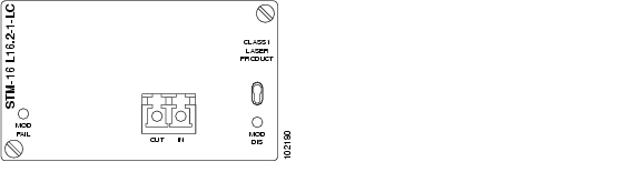
Figure 17-1 The physical connector is a LC connector. See Figure 17-2.
Figure 17-2 STM-16 L16.2-1-LC Module
17.2.2 Optical Budget
For definitions of optical parameters, see ITU-T Rec. G.957. Reference point S means transmit interface while R is the receive interface.
17.2.3 Compliance
L16.2-1-LC Interface compliance is given in Table 17-2.
Table 17-2 Compliance - L16.2-1-LC Interface
17.2.4 Example of Cable Planning
Typical cable parameters and link spans are found in Table 17-3 and Table 17-4.
Table 17-3 Typical Cable Parameters
Table 17-4 Typical Link Spans for 1xL-16.2-LC
17.2.5 Optical Rx Power Monitoring
The optical input power of the Rx interface is monitored and can be read from the Cisco EdgeCraft terminal.
![]()
![]()
![]()
![]()
![]()
![]()
![]()
![]()
Posted: Fri Sep 14 08:54:38 PDT 2007
All contents are Copyright © 1992--2007 Cisco Systems, Inc. All rights reserved.
Important Notices and Privacy Statement.