|
|

Table Of Contents
Octal LAN 10/100Base-TX Module with Mapper, E100-WAN-8
21.2.1 Grooming Mode (2xFE + SMAP)
21.2.2 Normal Mode (8xFE +SMAP)
Octal LAN 10/100Base-TX Module with Mapper, E100-WAN-8
21.1 Module Description
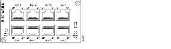
The module is a tributary module that supports both optical and electrical Ethernet interfaces, see Figure 21-1. The module contains 8 LAN Ethernet interfaces that support both 10Base-T and 100Base-TX according to the IEEE 802.3 specification. The interface supports both the half-duplex and the full-duplex modes.
The physical interface is RJ-45connectors. Every interface has two LED's, one LED indicates the link status and the other LED indicates the link speed. The module includes up to sixteen Ethernet to SDH mappers.
The module support both L1 and L2 services. It consists of the following functionality:
•
Ethernet features
•
•
•
•
•
•
•
Figure 21-1 Octal LAN 10/100Base-TX Module with Mapper, E100-WAN-8
21.1.1 Ethernet Features
The module supports both L1 and L2 services. The number of physical interfaces is eight. They can be independent configured as electrical 10/100 Base-TX.
The policer performs the following functions:
•
•
•
The module includes two Ethernet switches of which one is directly connected to the mapper. This switch and mapper provides eight mappers that can be used in a L2 solution.
The other Ethernet switch is connected to the policer. The mapper and physical interfaces are also connected to the policer.
The following options are available in the policer:
•
•
•
Sixteen mappers are available if none of the physical interfaces are used.
21.1.2 SDH Features
The tributary module includes the following SDH functionality:
GFP-F encapsulation of Ethernet traffic
•
•
•
•
•
21.1.3 Electrical Interfaces
The module supports up to eight electrical Ethernet interfaces. The interfaces support both 10 Base-T and 100 Base-TX.
21.1.4 LED Indicators
Visual indicators (LED's) provide the status of the module.
21.2 Configuration
In addition to the physical interfaces the module contains two 8 port Ethernet switches, connected together via the internal G-link interface towards the crossbar, and two 8 port mapper circuits. The module is configurable into two main operation modes:
•
•
21.2.1 Grooming Mode (2xFE + SMAP)
In this operation mode physical port 1 and 2 (LAN ports) are connected to the Ethernet switch, physical port 3-8 is unused. The 14 remaining Ethernet switch ports (WAN ports are connected to the mapper circuits; two mapper circuits are left unconnected. In this configuration the module is intended for grooming of traffic from a large number of remotely located devices.
21.2.2 Normal Mode (8xFE +SMAP)
In this operation mode 8 of the Ethernet switch ports are connected to 8 mapper ports (WAN ports). The 8 physical interfaces can independently be configured to operate as a L1 port (LAN port), directly connected to one of the 8 mapper ports, or as a L2 port (LAN port), connected to one of the 8 Ethernet switch ports.
The mapper circuits supports the mapping functionality described in 5.2 Ethernet over SDH mapping, page 5-17.
The LAN and WAN ports offers the IP functionality described in 5.4 IP Features, page 5-24.
21.3 Power Consumption
The power consumption is 27,5 W.
Note
21.4 External Interface
The following sub-sections describes the external interface.
21.4.1 Description
The interface is a 10Base-T and 100Base-TX Ethernet interface according to the IEEE 802.3 specification.
21.4.2 Connector type
The connectors are 8x RJ-45 Fast Ethernet
21.4.2.1 Pin Out
Pins available:
–
Spare pins:
–
LAN1 to LAN8 are numbered from lower left corner. Traffic and link status are indicated in a LED (light pipe) which is formed as an arrow, pointing on the actual port.
21.4.3 Compliance
10/100Base-T interface compliance is described in Table 21-1.
![]()
![]()
![]()
![]()
![]()
![]()
![]()
![]()
Posted: Fri Sep 14 08:57:00 PDT 2007
All contents are Copyright © 1992--2007 Cisco Systems, Inc. All rights reserved.
Important Notices and Privacy Statement.