|
|

Table Of Contents
4.2.4 Install External Ground to the ONS 15305
4.4.1 Installation in Restricted Access Locations
4.4.2 Install the ONS 15305 -48 VDC Power
4.4.3 Install the ONS 15305 -AC 230V Power
4.5 Installation of Service Modules
4.5.2 Hot Insertion and Removal
4.6 Interconnections and Cable Handling
4.6.1 Install the ONS 15305 Fiber Cable
4.6.2 Install the ONS 15305 Electrical Cable
Installation
This chapter provides instructions for installing the Cisco ONS 15305.
Note
The instructions in this section primarily address the installation of the ONS 15305, and modules supplied by Cisco Systems. When installing racks, electrical wiring, raceways, and other equipment not covered in this manual, you should follow all local, state, federal, or international (if applicable) codes and regulations.
Caution
4.1 Installation Overview
You should be thoroughly familiar with the instructions in this manual before starting any work. Use the following instructions when installing the ONS 15305.
Step 1
Step 2
Step 3
Step 4
Step 5
Step 6
4.2 Installation Planning
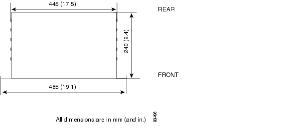
Based on the configuration to be installed, determine the size, number, and location of racks, as well as the ONS 15305 installation requirements. The following are unit dimensions to take into consideration when installing the ONS 15305. The ONS 15305 can be installed in 485 mm (19-in.) equipment racks, and can be adapted for 600 mm ETSI (23.6-in.) racks. The racks must be accessible from the front and rear for equipment installation.
Note
Use the following considerations:
•
•
•
•
•
•
Note
4.2.1 Required Items
In addition to a standard installers tool kit, the following items are also required:
•
•
•
•
•
•
•
•
•
•
4.2.2 Installation Guidelines
When installing ONS 15305 equipment into a rack, follow these guidelines:
•
•
•
•
Figure 4-1 shows the outer dimensions of the ONS 15305 system equipment.
Figure 4-1 Outer Dimensions of the ONS 15305 System
4.2.3 Install Ground to 48 V
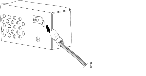
The ONS 15305 cabinet must always be tied to a suitable earth reference potential as described in section Install External Ground to the ONS 15305. The 48V power interface of ONS 15305 is galvanically insulated from the cabinet and the positive pole of the 48V supply (0 VDC) must always be connected to the same earth potential at the station battery, PDP side. See section "Install the ONS 15305 -48 VDC Power". The location of the power connector on the ONS 15305 is shown in Figure 4-2.
Figure 4-2 ONS 15305 - DC Power Module
4.2.4 Install External Ground to the ONS 15305
It is vital that the ONS 15305 cabinet is properly grounded.
When installed in a rack, the ONS 15305 cabinet will be tied to the rack reference potential through the mounting brackets (earth, ground potential).
Note
When not installed in a rack, the cabinet can be tied to an earth reference potential through the ground connector of the power supply plug as shown in Figure 4-2 or by mounting an extra connector to one of the cabinet screws as in Figure 4-3.
Figure 4-3
Ground Connector Position on the ONS 15305
Install the Ground Connector
Step 1
Step 2
Step 3
Step 4
Step 5
Step 6
Figure 4-4
Connection of the Ground Cable with a Crimp Tool
4.2.5 Power Considerations
The ONS 15305 can be powered using a Central Office power supply of -48 VDC with a VDC return. The ONS 15305 supports redundant 48 VDC power supplies but if used, the two supplies should be independently powered.
4.3 Fiber Cleaning
Cletop cleaning cassettes (type A for LC connectors) must be used to clean the fiber connectors and adapters before installing fiber. A video inspection instrument, with optical adapters for LC connectors is also required to inspect the fiber connectors and adapters before installing fiber.
Note
Warning
Warning
Warning
Clean Fiber Connectors
Follow the procedure below when cleaning Fiber Connectors.
Step 1
Step 2
Step 3
Step 4
Step 5
Clean Fiber Adapters
Follow the procedure below when cleaning Fiber Adapters.
Step 1
Step 2
Step 3
Step 4
Step 5
4.4 ONS 15305 Installation
Use the following procedures to install the ONS 15305 in an equipment rack, but verify first that at least 3 RU of rack space is available.
When installing the ONS 15305, you can also use the extension brackets, included in the ONS 15305 accessory kit, to convert a 485-mm (19-inch) rack to a 600-mm (23.6-inch) rack.
Note
Note
Caution
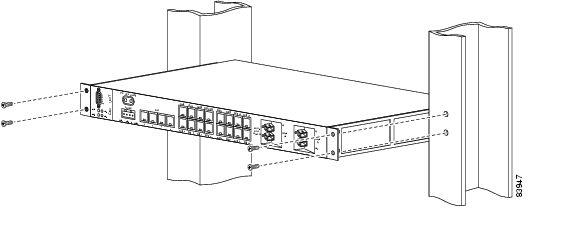
Mount the ONS 15305 in an Equipment Rack
Use the following procedure to install the ONS 15305 in an equipment rack.
Step 1
Step 2
Step 3
Figure 4-5 The Connector Array in Front, in a 19-in. Rack
Mount the ONS 15305 in an Equipment Rack Using Extension Brackets
The ONS 15305 can be installed in a 600-mm (23.6-in.) rack using the extension brackets. You need two 1 RU extension brackets for this procedure.
Step 1
Step 2
Step 3
4.4.1 Installation in Restricted Access Locations
The ONS 15305 can be installed in a restricted access location (RAL) or outside of an RAL.
4.4.1.1 Definitions
Restricted Access Location
A restricted access location is a site location for equipment where both of the following paragraphs apply:
•
•
SELV Circuits
Safety Extra-Low Voltage (SELV) circuits are ports that have maximum DC working voltage level less than 60 V (42.4 VAC). In addition, the ports must not be connected to telecommunication networks as defined in EN 60950 (see CEI/ IEC 60950-1 2001-10, standard clause 1.2.13.8).
In practice, the electrical cables must not exit the building. In addition, the electrical cables must be connect to equipment that meets one of the following requirements:
•
•
•
Telecommunication Network
A telecommunication network is a metallically terminated transmission medium intended for communication between equipment that might be located in separate buildings, excluding:
•
•
•
TNV Circuit
A TNV circuit in the equipment to which the accessible area of contact is limited. A TNV circuit is so designed and protected that, under normal operating conditions and single fault conditions (see CEI/IEC 60950-1 2001-10, standard clause 1.4.14), the voltages do not exceed specified limit values.
4.4.1.2 Installation in Restricted Access Location
After installation in a RAL, such as in a telecommunications center, the ONS 15305 must be properly installed in a rack with brackets or in other ways properly connected to a safety ground. The ONS 15305 48-VDC power must not be powered from a source external to the RAL. All communication interfaces
used must be limited to SELV.4.4.1.3 Installation Outside of a Restricted Access Location
After installation in a non-RAL location, the ONS 15305 48-V power and all communication ports used must be connected to SELV circuits, for example, a port on a personal computer or 10/100-Mbit Ethernet hub/router or other information technology (IT) equipment. The 48-VDC power must not exceed 60 VDC, and must be powered from a certified external power supply unit (PSU) or a battery unit (with no connection to -48 V telecommunications voltage).
4.4.2 Install the ONS 15305 -48 VDC Power
The following procedure explains how to install ONS 15305 DC power connections.
4.4.2.1 Connect the ONS 15305 A-side and B-side Power Connections to the PDP
Warning
Warning
Caution
Table 4-1 displays the color of the wire with their function.
Table 4-1 Power Cable
Brown
OV
Blue
-48 VDC
Black
-48 VDC
Green/yellow
GND
Step 1
Step 2
Note
Note
Step 3
Step 4
Step 5
Step 6
Step 7
Step 8
Note
Note
Step 9
Step 10
Step 11
Note
4.4.3 Install the ONS 15305 -AC 230V Power
The following procedure explains how to install ONS 15305 AC power connections.The AC 230 Power module is shown in Figure 4-6.
Figure 4-6 AC 230V
Module
Warning
Warning
Warning
Caution
4.4.3.1 AC 230V Module Not Installed in ONS15305
Warning
4.4.3.2 Power On
Warning
Step 1
Step 2
4.4.3.3 Power Off
Warning
Caution
Step 1
Step 2
Step 3
4.5 Installation of Service Modules
This section describes installation procedures that are common and independent of Service module type.
For details on each Service modules see separate chapters. Interconnections and cabling are described in Interconnections and Cable Handling.
It is possible to freely mix the four interface modules. There are no fixed positions for specific modules.
Note
Insertion or withdrawal of new modules does not affect the other modules. No manual configuration is needed, if a module is replaced with a module of the same type.
It is possible to protect a module by adding a redundant module in the chassis.
All modules store inventory data in non-volatile memory. The inventory data is accessible from the system controller and the management system.
All modules contain a LED that indicates the status of the module. The LED is green when the module is active. The LED is red if the module is failed. The LED is extinguished when the module is deactivated.
All modules supports hot insertion and removal. When a module shall be replaced the switch must be activated and the user must wait for the LED to extinguish before the module is removed. It is also possible to deactivate the module from the Cisco EdgeCraft terminal. A special tool, the Card Extraction Tool is needed to activate this switch.
The following Service modules are described in separate chapters:
•
•
•
•
•
•
•
•
•
•
•
•
•
•
4.5.1 LEDs
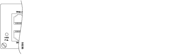
There is one status LED indicator on the front of a Service module, as shown in Figure 4-7.
LED indications is described in Table 4-2
Figure 4-7 Location of LED for Module Failure
A module is taken Out-of-Service by an operator shutdown-command or by activation of the shutdown button (see Figure 4-8).
Note
Note
4.5.2 Hot Insertion and Removal
The ONS 15305 service modules support hot insertion and removal. Each module contains a switch that is activated when the module is removed. A special tool, the Card Extraction Tool, must be used to activate the switch.
Figure 4-8 Switch to be Activated When the Module is Removed
When the module is replaced the switch must be activated and then the MOD FAIL LED must be extinguished before the module is removed.
Caution
It is also possible to deactivate the module from the craft terminal, Cisco EdgeCraft.
When the switch is activated, the module is disabled in SW, and the MOD FAIL LED is switched off (for modules carrying IP, the LED blinks during SW cleanup, and extinguishes afterwards). The module can now be removed. Please see Figure 4-9
Figure 4-9 Card Extraction Tool
4.6 Interconnections and Cable Handling
4.6.1 Install the ONS 15305 Fiber Cable
Caution
To install fiber-optic cables in the ONS 15305, connect a fiber cable with LC connector type to the transmit- and receive ports of the transmission system. On an ONS 15305 module, the transmit and receive ports are located at the connector array of the unit. The receive port is named IN and the transmit port is named OUT.
Cisco recommends that you label the transmit- and receive fiber (before installation) to and from the optical transmission system at each end of the fiber span to avoid confusion with cables that are similar in appearance.
Warning
Warning
Warning
Connect the Fiber Cable
Step 1
Step 2
Step 3
Step 4
Step 5
4.6.2 Install the ONS 15305 Electrical Cable
Caution
To install electrical connection cables in the ONS 15305, connect the electrical cable with the corresponding ports of the transmission system. On the ONS 15305 module, the electrical ports are located at the connector array of the system. All electrical cables are equipped with RJ-45 connectors. The alarm cable is equipped with a DS-9 connector. Cisco recommends that you label the electrical cable at each end before installation to avoid confusion with cables that are similar in appearance.
Caution
Connect the Electrical Cables
Step 1
Step 2
Step 3
4.7 Initial Configuration
Both initial and further configuration steps are described in the Cisco Edge Craft User Guide. Please see Chapter 1 of that guide for instructions on how to set up the necessary communication parameters enabling access to the element through Cisco Edge Craft over the management port. All other management features for the Cisco ONS 15305 are also described in the Cisco Edge Craft User Guide.
Tip
![]()
![]()
![]()
![]()
![]()
![]()
![]()
![]()
Posted: Fri Sep 14 10:20:09 PDT 2007
All contents are Copyright © 1992--2007 Cisco Systems, Inc. All rights reserved.
Important Notices and Privacy Statement.