|
|

Table Of Contents
Troubleshooting 8-Port FC/GE Aggregation Card Problems
6.2 Initial Troubleshooting Checklist
6.3 Troubleshooting 8-Port FC/GE Aggregation Card Interface Problems
6.3.1 FC/FICON Encapsulated Gigabitphy Interface Is Down
6.3.2 GE Encapsulated Gigabitphy Interface Is Down
6.3.3 Gigabitphy Interface Is Administratively Down
6.3.4 Client Equipment Interface Connected to the 8-Port FC/GE Aggregation Card Is Not Up
6.3.5 Client Equipment Detects CVRD Errors
6.3.6 Transmit Frame Count Is Not Incrementing
6.3.7 Local Interface with GE Encapsulation Receives Frames But Not the Remote Interface
6.3.8 FC/FICON Encapsulated Gigabitphy Interface Receives CRC Errors from Trunk Card
6.3.9 Both the Local and Remote Gigabit Interfaces Are Down
6.3.10 Gigabitphy Interface Not Created
6.4 Debugging Problems Using show controller Command Output
6.5 Troubleshooting 8-Port FC/GE Aggregation Card Problems Using Loopbacks
Troubleshooting 8-Port FC/GE Aggregation Card Problems
This chapter describes how to troubleshoot 8-port FC/GE aggregation card interface problems. This chapter includes the following sections:
•
Overview
•
•
•
6.1 Overview
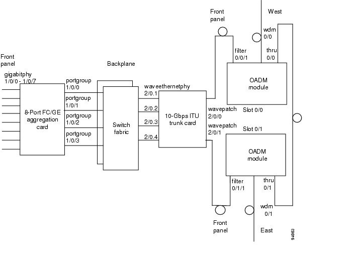
The 8-port FC/GE aggregation card uses SFP (small form-factor pluggable) optical transceivers to provide up to eight configurable client interfaces. Each interface can be configured in the CLI (command-line interface) for FC (Fibre Channel), FICON (fiber connection), or GE (Gigabit Ethernet) traffic.
Figure 6-1shows an example path of a client signal through the Cisco ONS 15530 and the associated interfaces.
Figure 6-1 Interfaces for an 8-Port FC/GE Aggregation Card
6.2 Initial Troubleshooting Checklist
Follow this initial checklist before proceeding with the troubleshooting procedures:
•
•
•
•
•
•
•
6.3 Troubleshooting 8-Port FC/GE Aggregation Card Interface Problems
This section contains troubleshooting procedures for 8-port FC/GE aggregation card interface problems.
6.3.1 FC/FICON Encapsulated Gigabitphy Interface Is Down
Symptom A gigabitphy interface encapsulated for FC or FICON traffic is down because of Loss of Light.
Table 6-1 describes the potential causes of the symptom and the solutions.
6.3.2 GE Encapsulated Gigabitphy Interface Is Down
Symptom A gigabitphy interface encapsulated for GE traffic is down because of Loss of Light or Loss of Sync.
Table 6-2 describes the potential causes of the symptom and the solutions.
6.3.3 Gigabitphy Interface Is Administratively Down
Symptom A gigabitphy interface is administratively down and cannot carry any type of traffic.
Table 6-3 describes the potential causes of the symptom and the solutions.
6.3.4 Client Equipment Interface Connected to the 8-Port FC/GE Aggregation Card Is Not Up
Symptom The client signal to one gigabitphy interface fell below an alarm threshold falls below an alarm threshold value.
Table 6-4 describes the potential causes of the symptom and the solutions.
6.3.5 Client Equipment Detects CVRD Errors
Symptom The client equipment detects CVRD (code violation and running disparity) errors and the gigabitphy interface shows Loss of Sync.
Table 6-5 describes the potential causes of the symptom and the solutions.
6.3.6 Transmit Frame Count Is Not Incrementing
Symptom The Transmit Frame Count field in the show interfaces command output for the gigabitphy interface is not incrementing.
Table 6-6 describes the potential causes of the symptom and the solutions.
Table 6-6 Transmit Frame Count Is Not Incrementing
An interface in the path is administratively shut down.
1.
2.
The client receive signal power is not strong enough.
1.
a.
b.
2.
a.
b.
c.
The cross connection is not properly configured.
1.
2.
3.
The flow identifier is not configured.
1.
2.
3.
6.3.7 Local Interface with GE Encapsulation Receives Frames But Not the Remote Interface
Symptom A gigabitphy interface on the local system receives frames but the remote interface does not receive any frames.
Table 6-7 describes the potential causes of the symptom and the solutions.
6.3.8 FC/FICON Encapsulated Gigabitphy Interface Receives CRC Errors from Trunk Card
Symptom A gigabitphy interface encapsulated with either FC or FICON shows CRC (cyclic redundancy check) errors received from the trunk cards. The show interfaces command for the interface shows NO TX CRC.
Table 6-8 describes the potential cause of the symptom and the solution.
Table 6-8 FC/FICON Encapsulated Gigabitphy Interface Receives CRC Errors from Line Card
The transmit buffer is not correctly configured.
1.
2.
For information on setting the transmit buffer size on 8-port FC/GE aggregation card, refer to the Cisco ONS 15530 Configuration Guide .
The power of the signal received from the trunk card is close to or below the low warning threshold.
1.
2.
6.3.9 Both the Local and Remote Gigabit Interfaces Are Down
Symptom The local gigabitphy interface is down due to a local condition while the remote gigabitphy interface is down and the remote gigabitphy interface is down due to a keepalive timeout.
Table 6-9 describes the potential cause of the symptom and the solution.
6.3.10 Gigabitphy Interface Not Created
Symptom A gigabitphy interface does not appear in the configuration and the system does not recognize it.
Table 6-10 describes the potential cause of the symptom and the solution.
6.4 Debugging Problems Using show controller Command Output
You can use the show controllers command output to determine and resolve problems on your 8-port FC/GE aggregation card. The following is an example of the command output:
Switch# show controllers gigabitphy 4/0/2Line card base addr: 0x400000Optical Transceiver: Multi-ModeFC Egress FIFO Underflow: 0FC Egress FIFO Overflow: 0Uplink Request FIFO full: 0Uplink Data FIFO full: 0Downlink Descriptor FIFO full: 0Downlink Data FIFO full: 0Tx CRC errors: 0Registers specific to fabric port 2:Encapsulation FPGA 0 base addr: 0x80000Version.................: 0x50410621ID......................: 0x40000Port Control:Line interface type................: GigabitEthernetLine port transmit.................: enabledLine port receive..................: enabledPort Control 1..........: 0x960Loopback Control:Gigabit interface loopback.........: disabledLine interface loopback............: disabledPort State..............: 0x0FC interface.......................: activePort Fail Cause.........: 0x11Loss Of sync.......................: yesLoss Of signal.....................: noReceive degrade....................: noTransmit fault.....................: noInactive inflow control mode.......: yesEgress fifo full...................: noTransceiver present................: noPort Fail Mask..........: 0x3FLoss Of sync.......................: yesLoss Of signal.....................: yesReceive degrade....................: yesTransmit fault.....................: yesInactive in flow control mode......: yesEgress fifo full...................: yesTransceiver present................: noPort Fail Status........: 0xE2Loss Of signal from xcvr...........: noLoss Of signal from phy............: yesEgress fifo full...................: noTransmit fault from phy............: noTransceiver present................: noLoss of sync.......................: yesInactive...........................: yesEgress fifo empty..................: yesPort Fail Status Mask...: 0xF6Loss Of signal from xcvr...........: noLoss Of signal from phy............: yesReceive degrade....................: yesTransmit fault from phy............: noTransceiver present................: yesLoss of sync.......................: yesReset Register..........: 0xFF00Ordered-Set Control.....: 0x0Credit Mgmt Control:Credit memory size.................: 0x800Port login mode enable.............: yesFlow control enable................: noCredit Mgmt Status:Hudson Login Complete..............: noClient Login Complete..............: noExcess Credit Detect...............: noFlow Control Active................: noIndirect Address........: 0x8130007FIndirect Data...........: 0x11FC Port 2 Source ID.....: 0x0FIFO Hi Control.........: 0x4FIFO Low Control........: 0x2OFC Control.............: 0x8400C3PHY Control:External phy loopback..............: disabledExternal phy.......................: lockedExternal phy byte sync.............: noExternal phy internal byte sync....: enabledTransceiver Control:Auto laser shut....................: disabledTransceiver bandwidth..............: fullLaser shut control for simi interface: enabledTransceiver........................: presentLaser Control:External transceiver transmit......: disabledWrite for ext transceiver tx enable: disabledExternal transceiver transmit......: OFFHardware FLC.......................: disabledClock Control...........: 0x0Mux/Demux FPGA 0 base addr: 0x40000Registers specific to client port 2:Uplink0 SII Register....: 0xFF (255)GE0 MTU.................: 0x27F80040GE0 Tx CRC Threshold....: 0x64Table 6-11 describes some of the fields in the show controllers command output that are very useful.
6.5 Troubleshooting 8-Port FC/GE Aggregation Card Problems Using Loopbacks
This section describes how to use software loopbacks to perform fault isolation for signals on 8-port FC/GE aggregation cards. The 8-port FC/GE aggregation card supports two types of software loopbacks:
•
•
To perform further loopback operations, see the "8.4 Troubleshooting 2.5-Gbps ITU Trunk Card Problems Using Loopbacks" section on page 8-5, the "9.4 Troubleshooting 10-Gbps ITU Trunk Card Problems Using Loopbacks" section on page 9-5, and the "10.4 Troubleshooting 10-Gbps ITU Tunable Trunk Card Problems Using Loopbacks" section on page 10-6.
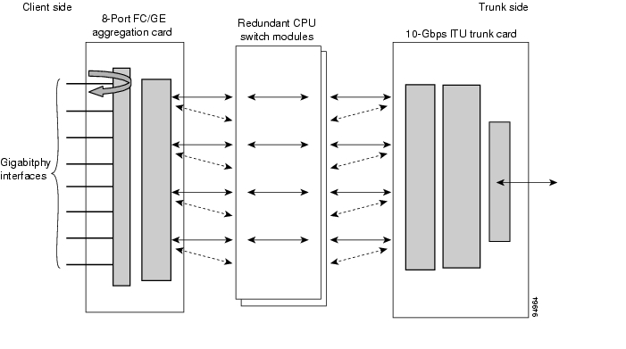
6.5.1 Facility Loopbacks
Facility loopbacks on 8-port FC/GE aggregation cards verify the functioning of the SFP optics from the client side (see Figure 6-2).
Figure 6-2 Facility Loopback Example
To create a facility loopback:
Step 1
Step 2
Step 3
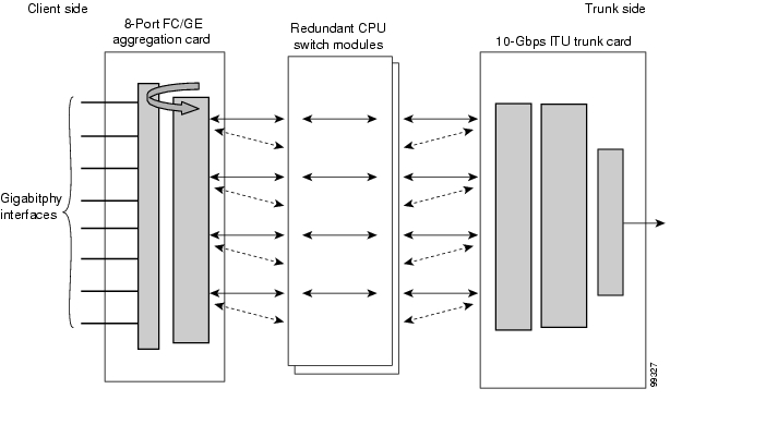
6.5.2 Terminal Loopbacks
Terminal loopbacks verify the functioning of the 8-port FC/GE aggregation cards from the trunk side (see Figure 6-3).
Figure 6-3 Terminal Loopback Example
To create a terminal loopback:
Step 1
Step 2
Step 3
![]()
![]()
![]()
![]()
![]()
![]()
![]()
![]()
Posted: Mon Apr 30 14:24:02 PDT 2007
All contents are Copyright © 1992--2007 Cisco Systems, Inc. All rights reserved.
Important Notices and Privacy Statement.