|
|

Table Of Contents
Troubleshooting 2.5-Gbps ITU Trunk Card Problems
8.2 Initial Troubleshooting Checklist
8.3 Troubleshooting 2.5-Gbps ITU Trunk Card Interface Problems
8.3.1 Waveethernetphy Interface Down and Shows Loss of Lock
8.3.2 Waveethernetphy Interface Down and Shows Loss of Sync
8.3.3 CVRD Errors on the Waveethernetphy Interface
8.3.4 CRC and CDL HEC Errors on the Waveethernetphy Interface
8.3.5 Ethernetdcc Interface Down
8.4 Troubleshooting 2.5-Gbps ITU Trunk Card Problems Using Loopbacks
Troubleshooting 2.5-Gbps ITU Trunk Card Problems
This chapter describes how to troubleshoot 2.5-Gbps ITU trunk card problems. This chapter includes the following sections:
•
Overview
•
•
•
8.1 Overview
The 2.5-Gbps ITU trunk card converts an aggregated 2.5-Gbps signal to an ITU-compliant wavelength, or channel. The Cisco ONS 15530 supports two types of 2.5-Gbps ITU trunk cards:
•
•
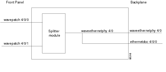
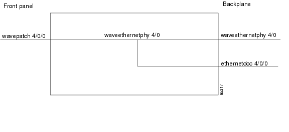
Figure 8-1 and Figure 8-2 show the interface models for the two versions of the 2.5-Gbps ITU trunk card, splitter and nonsplitter.
Figure 8-1 Splitter 2.5-Gbps ITU Trunk Card Interfaces
Figure 8-2 Nonsplitter 2.5-Gbps ITU Trunk Card Interfaces
8.2 Initial Troubleshooting Checklist
Follow this initial checklist before proceeding with the troubleshooting procedures:
•
•
•
•
•
•
•
•
8.3 Troubleshooting 2.5-Gbps ITU Trunk Card Interface Problems
This section contains troubleshooting procedures for 2.5-Gbps ITU trunk card interface problems.
8.3.1 Waveethernetphy Interface Down and Shows Loss of Lock
Symptom The waveethernetphy interface is in a down state and the signal quality shows a Loss of Lock.
Table 8-1 describes the potential causes of the symptom and the solutions.
8.3.2 Waveethernetphy Interface Down and Shows Loss of Sync
Symptom The waveethernetphy interface is in a down state and the signal quality shows a Loss of Sync. Also, the show facility-alarm status command output shows an alarm message.
Table 8-2 describes the potential causes of the symptom and the solutions.
8.3.3 CVRD Errors on the Waveethernetphy Interface
Symptom The waveethernetphy interface is in a down state and in the show interfaces command output the Code violation and running disparity error count (64b66b CVRD) field are increasing and the Signal Condition field shows "Signal Fail Threshold exceeded."
Table 8-3 describes the potential causes of the symptom and the solutions.
8.3.4 CRC and CDL HEC Errors on the Waveethernetphy Interface
Symptom The waveethernetphy interface is in a down state, the CRC error count and the CDL HEC error counts in the show interfaces command output is increasing, and the Signal Condition field shows "Signal Fail Threshold exceeded" or "Signal Degrade Threshold exceeded."
Table 8-3 describes the potential causes of the symptom and the solutions.
Table 8-4 CRC and CDL HEC Errors on the Waveethernetphy Interface
The data is corrupted somewhere in the data path.
1.
2.
8.3.5 Ethernetdcc Interface Down
Symptom The ethernetdcc interface is down and pings across the interface fail.
Table 8-5 describes the potential cause of the symptom and the solution.
8.4 Troubleshooting 2.5-Gbps ITU Trunk Card Problems Using Loopbacks
This section describes how to use software loopbacks to perform fault isolation for signals on 2.5-Gbps ITU trunk cards. The 2.5-Gbps ITU trunk card supports two types of software loopbacks:
•
•
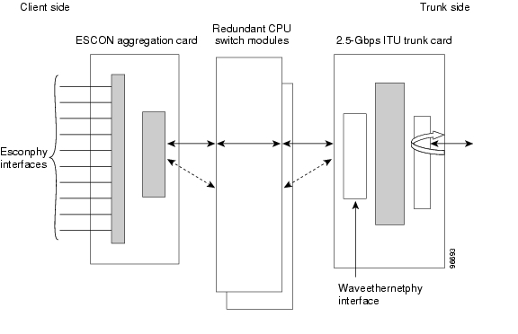
8.4.1 Facility Loopbacks
A facility loopback verifies the functioning of the 2.5-Gbps ITU trunk card from the trunk side (see Figure 8-3).
Figure 8-3 Facility Loopback Example on a 2.5-Gbps ITU Trunk Card
Procedure: Create a Facility Loopback
Step 1
Step 2
Step 3
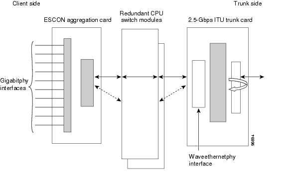
8.4.2 Terminal Loopbacks
A terminal loopback verifies the functioning of the 2.5-Gbps ITU trunk card from the switch fabric side (see Figure 8-4).
Figure 8-4 Terminal Loopback Example on a 2.5-Gbps ITU Trunk Card
To create a terminal loopback:
Step 1
Step 2
Step 3
![]()
![]()
![]()
![]()
![]()
![]()
![]()
![]()
Posted: Mon Apr 30 13:54:01 PDT 2007
All contents are Copyright © 1992--2007 Cisco Systems, Inc. All rights reserved.
Important Notices and Privacy Statement.