cc/td/doc/product/mels/15530
hometocprevnextglossaryfeedbacksearchhelp
PDF

Table Of Contents

Troubleshooting 8-Port Multi-Service Muxponder Problems

7.1  Overview

7.2  Initial Troubleshooting Checklist

7.3  Troubleshooting Multirate Interface Problems

7.3.1  Loss of Light on Multirate Interfaces

7.3.2  Loss of Sync on Multirate Interfaces

7.3.3  Loss of Lock on Multirate Interfaces

7.3.4  Loss of Signal on Multirate Interfaces

7.3.5  AIS Error on Multirate Interface Encapsulated for T1 or E1

7.3.6  Multirate Interface Displays Remote Client Error Message

7.3.7  Multirate Interface Detects CVRD Errors

7.3.8  Multirate Interface Not Appearing In Configuration

7.3.9  Encapsulation is Rejected on the Multirate Interface

7.4  Troubleshooting Trunk-Side Interfaces

7.4.1  Wavesonetphy Interface Down and Shows Loss of Lock

7.4.2  Wavesonetphy Interface Down and Shows Loss of Frame

7.4.3  B1 Errors on the Wavesonetphy Interface

7.4.4  Sdcc Interface Down

7.5  Troubleshooting TSI Protocol Problems

7.5.1  End-to-End Traffic Not Flowing Due to TSI Problems

7.6  Troubleshooting 8-Port Multi-Service Muxponder Problems Using Loopbacks

7.6.1  Client-Side Facility Loopbacks

7.6.2  Client-Side Terminal Loopbacks

7.6.3  Trunk-Side Facility Loopbacks

7.6.4  Trunk-Side Terminal Loopbacks

7.6.5  Troubleshooting Protocol Level Errors in an End-to-End Scenario


Troubleshooting 8-Port Multi-Service Muxponder Problems


This chapter describes how to troubleshoot 8-port multi-service muxponder problems. This chapter includes the following sections:

Overview

Initial Troubleshooting Checklist

Troubleshooting Multirate Interface Problems

Troubleshooting Trunk-Side Interfaces

Troubleshooting TSI Protocol Problems

Troubleshooting 8-Port Multi-Service Muxponder Problems Using Loopbacks

7.1  Overview

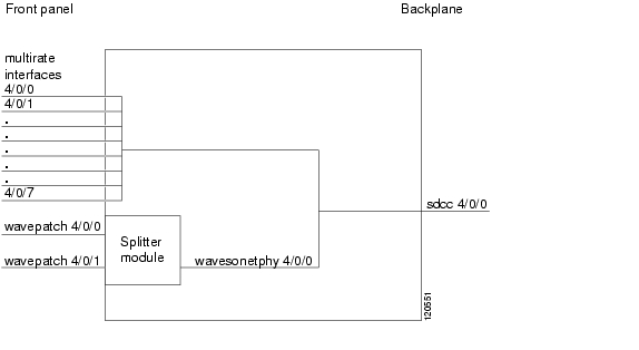
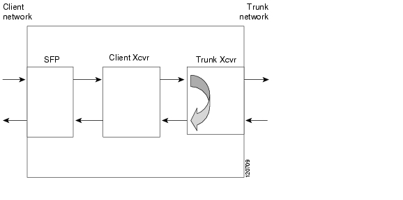
The 8-port multi-service muxponder aggregates up to eight ports of client traffic into a 2.5-Gbps DWDM trunk circuit. The muxponder transports a mix of different protocols among sites in a metropolitan DWDM network. The protocols that can be aggregated and transported range from high-speed services such as Fibre Channel and Gigabit Ethernet to low-speed services such as OC-3, Fast Ethernet, or even T1 or E1.

The 8-port multi-service muxponder uses SFPs for the client signals. There are no restrictions on populating the line card with SFPs. For example, you can mix a single-mode SFP with a multimode SFP on the same muxponder.

Figure 7-1 shows the interfaces of the 8-port multi-service muxponder.


Note Although the 8-port multi-service muxponder uses a SONET-like framing structure to aggregate multiple client data streams, it is not SONET compliant on the optical trunk output. The muxponder ITU compliant optical trunk output must be used in an end-to-end configuration and cannot be connected to a SONET/SDH OADM.


Figure 7-1 8-Port Multi-Service Muxponder Interfaces (Splitter Shown)

7.2  Initial Troubleshooting Checklist

Follow this initial checklist before proceeding with the troubleshooting procedures:

Ensure the trunk laser is not shut down on the wavesonetphy interface, and that the laser frequency is correctly configured.

Ensure that TSI (time slot interface) mapping is enabled on the wavesonetphy interfaces.

Ensure that the sdcc interface is administratively up.

Issue the show interfaces command to ensure the multirate, wavesonetphy, wavepatch, and sdcc interfaces are administratively up and all interfaces on the signal path are administratively up, with no errors. Ensure the trunk receive power level is within the valid range (-28 to -8 dBm).

Issue the show tsi command to ensure that the TSI mapping is correct.

Ensure that the 8-port multi-service muxponder LEDs are in the proper state.

Issue a show facility-alarm status command to display the alarms on the interfaces.

Ensure the 8-port multi-service muxponders are patched to the correct OADM ports. Issue the show patch command to verify there are no frequency mismatches.

Ensure that all optical connectors are clean. Refer to the Cisco ONS 15530 Cleaning Procedures for Fiber Optic Connections document.

7.3  Troubleshooting Multirate Interface Problems

This section contains troubleshooting procedures for multirate interface problems on the 8-port multi-service muxponder.

7.3.1  Loss of Light on Multirate Interfaces

Symptom    A multirate interface encapsulated for optical Gigabit Ethernet, FC, FICON, ESCON, optical Fast Ethernet, SONET OC-3, SDH STM-1 or ITS is down due to Loss of Light.

Table 7-1 describes the potential causes of the symptom and the solutions.

Table 7-1 Multirate Interface Is Down Due to Loss of Light

Possible Problem
Solution

Wrong cable type is used.

Verify that the connected fiber type (SM/MM) is the same as that supported by the SFP on the multirate interface.

Cabling between the client equipment and the SFP is incorrect.

Verify that the transmit and receive cables are correctly installed.

Incoming power level is low.

Use a power meter to check the receive power level to the multirate interface. Adjust attenuation as needed.

Optical connectors are dirty.

Check the optical connections between the client equipment and the SFP for dirt, bends, or breaks. Clean or replace as necessary.

Refer to the Cisco ONS 15530 Cleaning Procedures for Fiber Optic Connections document.


7.3.2  Loss of Sync on Multirate Interfaces

Symptom    A multirate interface encapsulated for optical Gigabit Ethernet, FC, FICON, ESCON or DVB-ASI (Digital Video Broadcast-Asynchronous Serial Interface) is down due to Loss of Sync.

Table 7-2 describes the potential causes of the symptom and the solutions.

Table 7-2 Multirate Interface Is Down Due to Loss of Sync

Possible Problem
Solution

Interface improperly configured or incorrect protocol.

Issue the show interfaces multirate command to verify that the correct protocol is configured.

Optical connectors are dirty.

Check the optical connections between the client equipment and the SFP for dirt, bends, or breaks. Clean or replace as necessary.

Refer to the Cisco ONS 15530 Cleaning Procedures for Fiber Optic Connections document.


7.3.3  Loss of Lock on Multirate Interfaces

Symptom    A multirate interface encapsulated for optical Gigabit Ethernet, FC, FICON, ESCON, optical Fast Ethernet, SONET OC-3, SDH STM-1 or ITS is down due to Loss of Lock.

Table 7-3 describes the potential causes of the symptom and the solutions.

Table 7-3 Multirate Interface Is Down Due to Loss of Lock

Possible Problem
Solution

Incorrect protocol.

Issue a show interfaces multirate command to verify that the correct protocol is configured.

Optical connectors are dirty.

Check the optical connections between the client equipment and the SFP for dirt, bends, or breaks. Clean or replace as necessary.

Refer to the Cisco ONS 15530 Cleaning Procedures for Fiber Optic Connections document.


7.3.4  Loss of Signal on Multirate Interfaces

Symptom    A multirate interface encapsulated for DVB-ASI, copper Gigabit Ethernet, copper Fast Ethernet, SDI, T1, or E1 is down due to Loss of Signal.

Table 7-4 describes the potential causes of the symptom and the solutions.

Table 7-4 Multirate Interface Down Due to Loss of Signal

Possible Problem
Solution

Incorrect cable connection or wrong cable is used.

Ensure that the cable is connected. Also confirm that the pin outs are right for the cable connectors.

Line coding mismatch.

Ensure that the client equipment is configured as HDB3 for E1 or B8ZS for T1.

Auto negotiation mismatch between the multirate interface and the client interface.

For multirate interfaces encapsulated for copper Gigabit Ethernet or copper Fast Ethernet, ensure that the auto negotiation setting is the same as that of the connected client interface, either on or off.


7.3.5  AIS Error on Multirate Interface Encapsulated for T1 or E1

Symptom    AIS (alarm Indication signal) errors on a multirate interface encapsulated for T1 or E1.

Table 7-5 describes the potential cause of the symptom and the solution.

Table 7-5 AIS Errors on a Multirate Interface

Possible Problem
Solution

Connected client interface is sending AIS errors.

The client interface connected to the multirate interface may be shut down. Enable the client interface.


7.3.6  Multirate Interface Displays Remote Client Error Message

Symptom    The show interface multirate command output displays a "remote client error" message..

Table 7-6 describes the potential causes of the symptom and the solutions.

Table 7-6 Multirate Interface Displays "Remote Client Error" Message 

Possible Problem
Solution

Data receive error from remote client.

1. Issue a show interfaces multirate command to the local multirate interface, and look for the Data receive error from Remote Client error message.

2. Ensure that the same encapsulation is configured on the local and the remote multirate interface.

3. Issue the show tsi command on the local and remote equipment. Verify that the Tx time slots of the local interface are the same as the Rx time slots of the remote interface, and vice versa. For more information, refer to the Cisco ONS 15530 Configuration Guide.

4. Ensure that the trunk connection between the 15530 is up.

Error at the remote client.

Issue a show interfaces multirate command to the local multirate interface, and look for the Error at Remote Client error message. The peer client interface is down due one of the following reasons.

Administratively down

Down due to Loss of Lock

Down due to Loss of Light

Down due to Loss of Sync


7.3.7  Multirate Interface Detects CVRD Errors

Symptom    Multirate interface detects CVRD (code violation and running disparity) errors, and the multirate interface shows Loss of Sync.

Table 7-7 describes the potential causes of the symptom and the solutions.

Table 7-7 Multirate Interface Detects CVRD Errors 

Possible Problem
Solution

Incorrect protocol encapsulation.

1. Issue a show interfaces command to verify that the correct protocol is configured.

2. If the protocol is incorrect, then issue the encapsulation command to correct the protocol.

Low power level.

Use a power meter to ensure that the receive power level is within the correct range. Adjust the attenuation as needed.

Optical connectors are dirty.

Check the optical connections between the client equipment and the SFP for dirt, bends, or breaks. Clean or replace as necessary.

Refer to the Cisco ONS 15530 Cleaning Procedures for Fiber Optic Connections document.


7.3.8  Multirate Interface Not Appearing In Configuration

Symptom    A multirate interface does not appear in the configuration.

Table 7-8 describes the potential causes of the symptom and the solutions.

Table 7-8 Multirate Interface Does Not Appear In Configuration

Possible Problem
Solution

SFP is not installed.

Inspect the 8-port multi-service muxponder to verify that the SFP is correctly installed.


7.3.9  Encapsulation is Rejected on the Multirate Interface

Symptom    A multirate interface does not accept encapsulation.

Table 7-8 describes the potential causes of the symptom and the solutions.

Table 7-9 Encapsulation is Rejected on the Multirate Interface

Possible Problem
Solution

Encapsulation type is not supported.

Check the SFP to ensure it supports the required encapsulation.

Invalid rate for the encapsulation.

The SFP IDPROM may be corrupted. Replace the SFP.

TSI channels unavailable.

Issue the show tsi command to confirm that enough STS slots are available to configure the desired protocol.

Old encapsulation still present.

Issue the show interface multirate command to the interface to verify that no encapsulation is configured. If encapsulation is present, issue the no encapsulation command before configuring a new encapsulation.


7.4  Troubleshooting Trunk-Side Interfaces

This section contains troubleshooting procedures for trunk-side interface problems on the 8-port multi-service muxponder.

7.4.1  Wavesonetphy Interface Down and Shows Loss of Lock

Symptom    The wavesonetphy interface is down and shows Loss of Lock.

Table 7-10 describes the potential causes of the symptom and the solutions.

Table 7-10 Wavesonetphy Interface Down and Shows Loss of Lock 

Possible Problem
Solution

Incorrect laser frequency is configured.

Issue the show interfaces wavesonetphy command to verify the configured laser frequency. If necessary, issue the laser frequency command to configure the correct frequency.

The patch cables are incorrectly connected to the OADM module.

Issue the show patch command to verify the patch error status. If it shows a mismatch, connect the wavepatch interface of the 8-port multi-service muxponder to the correct filter ports on the OADM module.

Optical connectors are dirty.

Check the optical connections between the local and remote equipment for dirt, bends, or breaks. Clean or replace as necessary.

Refer to the Cisco ONS 15530 Cleaning Procedures for Fiber Optic Connections document.

The patch cables are faulty.

Check the local patch cables between thewavepatch interface of the 8-port multi-service muxponder and the OADM module for bends and breaks. If necessary, replace the patch cable.

Trunk cables are bad.

Check the incoming signal power level. Replace the cables if necessary.

The laser on the remote wavesonetphy interface is shut down.

Issue the no laser shutdown command on the remote wavesonetphy interface.


7.4.2  Wavesonetphy Interface Down and Shows Loss of Frame

Symptom    The wavesonetphy interface shows Loss of Frame.

Table 7-11 describes the potential causes of the symptom and the solutions.

Table 7-11 Wavesonetphy Interface Down and Shows Loss of Frame

Possible Problem
Solution

Optical connectors are dirty.

Check the optical connections between the local and remote equipment for dirt, bends, or breaks. Clean or replace as necessary.

Refer to the Cisco ONS 15530 Cleaning Procedures for Fiber Optic Connections document.

Excessive attenuation.

Use a power meter to ensure that the receive power level is within specifications for the interface. Reduce the attenuation as needed.

Overload (high receive power).

Use a power meter to ensure that the receive power level is within specifications for the interface. Attenuate the receive path as needed.


7.4.3  B1 Errors on the Wavesonetphy Interface

Symptom    The wavesonetphy interface shows B1 errors.

Table 7-12 describes the potential causes of the symptom and the solutions.

Table 7-12 Wavesonetphy Interface Shows B1 Errors 

Possible Problem
Solution

The ITU signal power is out of range.

Use a power meter to ensure that the receive power level is within -28 dBm and -8 dBm. Adjust the attenuation as necessary.

Optical connectors are dirty.

Check the optical connections between the local and remote equipment for dirt, bends, or breaks. Clean or replace as necessary.

Refer to the Cisco ONS 15530 Cleaning Procedures for Fiber Optic Connections document.


7.4.4  Sdcc Interface Down

Symptom    The sdcc interface is down.

Table 7-13 describes the potential causes of the symptom and the solutions.

Table 7-13 Sdcc Interface Down 

Possible Problem
Solution

Sdcc interface administratively shut down.

Issue a show interfaces sdcc command to determine the administrative status of the interface. If necessary, issue a no shutdown command to bring it up. Refer to the Cisco ONS 15530 Configuration Guide for more information.

The remote wavesonetphy interface laser is shut down.

Issue the no laser shutdown command on the remote wavesonetphy interface.


7.5  Troubleshooting TSI Protocol Problems

This section contains troubleshooting procedures for time slot interchange (TSI) mapping problems on the 8-port multi-service muxponder. The following example of the show tsi command output displays the TSI mapping of the Cisco ONS 15530 system:

Local system.

Switch1_1#show tsi
Port Local Peer Error Trunk STS Map
Encap Encap Transmit Receive

Card:9, TSI Ver:1, DCC:SDCC9/0/0, TSI-Protocol:Enabled

0. T1 T1 - 00 00 00 00 00 01 00 00 00 00 00 01
1. FC1 FC1 - 00 FF FE 00 00 0E 00 00 00 07 FF FE
2. T1 T1 - 00 00 00 00 00 01 00 00 00 00 00 01
3. CFE CFE - 07 00 00 00 00 00 00 00 00 38 00 00
4. E1 E1 - 00 00 00 00 00 01 00 00 00 00 00 01
5. CGE CGE - 00 00 01 FF FF F0 07 FF FF C0 00 00
6. T1 ESCON M 00 00 00 00 00 01 78 00 00 00 00 00
7. None None -
Available STS= 5
------------------------------

7.5.1  End-to-End Traffic Not Flowing Due to TSI Problems

Symptom    End-to-end traffic is not flowing due to TSI problems.

Table 7-14 describes the potential causes of the symptom and the solutions.

Table 7-14 End-to-End Traffic Not Flowing Due to TSI Problems 

Possible Problem
Solution

After configuring the encapsulation on the multirate interface a TSI mismatch alarm is seen on the console.

1. Issue the show tsi command to verify that both the local and remote equipment encapsulation are configured correctly. Both ends must be the same. An M in the error column of the output indicates an encapsulation mismatch between the local and remote ends.

2. If the local and remote Rx and Tx STS maps do not match, remove the encapsulation on the local multirate interface with the no encapsulation command and then reconfigure the encapsulation with the encapsulation command.


Note To change the interface encapsulation you must first shut down the multirate interface.


The show tsi command output does not display the Rx STS maps.

1. Confirm the sdcc interface is up and OSCP is in a 2-way state on both the local and remote switches.

2. Make sure TSI is enabled on both the local and remote switches


7.6  Troubleshooting 8-Port Multi-Service Muxponder Problems Using Loopbacks

This section describes how to use software loopbacks to perform fault isolation for signals on 8-port multi-service muxponders. The 8-port multi-service muxponder supports two types of software loopbacks on the client-side and trunk-side interfaces:

Facility loopbacks

Terminal loopbacks

7.6.1  Client-Side Facility Loopbacks

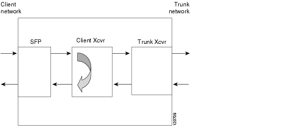
Client-side facility loopbacks on 8-port multi-service muxponders verify the functioning of the SFP optics from the client side (see Figure 7-2).

Figure 7-2 Client-Side Facility Loopback Example


Note For T1 and E1 encapsulations the loopback is performed on the SFP, not the client Xcvr.


To create a client-side facility loopback:


Step 1 Issue a loopback facility command on the multirate interface.

Step 2 Check that the traffic is reaching the client equipment.

Step 3 If the signal does not reach the client equipment, replace the SFP optics.


7.6.2  Client-Side Terminal Loopbacks

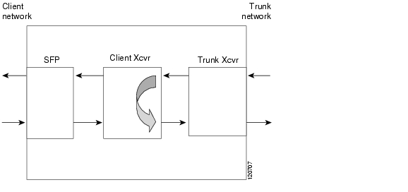
Client-side terminal loopbacks verify the functioning of the 8-port multi-service muxponders from the trunk side (see Figure 7-3).

Figure 7-3 Client-Side Terminal Loopback Example


Note For T1 and E1 encapsulations the loopback is performed on the SFP, not the client Xcvr.


To create a client-side terminal loopback:


Step 1 Issue a loopback terminal command on the multirate interface.

Step 2 Check that the traffic is reaching the remote client equipment.

Step 3 If the signal does not reach the far end, check the trunk fiber and the interfaces along the signal path. If the fiber is intact, replace the 8-port multi-service muxponder.


7.6.3  Trunk-Side Facility Loopbacks

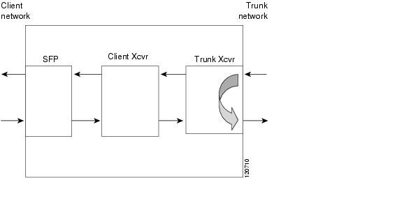
Trunk-side facility loopbacks on the wavesonetphy interface of the 8-port multi-service muxponders verify the functioning of the trunk optics from the trunk side (see Figure 7-4).

Figure 7-4 Trunk-Side Facility Loopback Example

To create a trunk-side facility loopback:


Step 1 Issue a loopback facility command on the wavesonetphy interface.

Step 2 Check that the traffic is reaching the remote client equipment.

Step 3 If the signal does not reach the far end, check the trunk fiber and the interfaces along the signal path. If the fiber is intact, replace the 8-port multi-service muxponder.


7.6.4  Trunk-Side Terminal Loopbacks

Trunk-side terminal loopbacks verify the functioning of the 8-port multi-service muxponders from the client side, up to the trunk side (see Figure 7-5).


Note Trunk side optics are not tested.


Figure 7-5 Trunk-Side Terminal Loopback Example

To create a trunk-side terminal loopback:


Step 1 Issue a loopback terminal command on the wavesonetphy interface.

Step 2 Check that the traffic is reaching the client equipment.

Step 3 If the signal does not reach the client equipment check the cables for bends and breaks, and if necessary, replace the SFP optics.


7.6.5  Troubleshooting Protocol Level Errors in an End-to-End Scenario

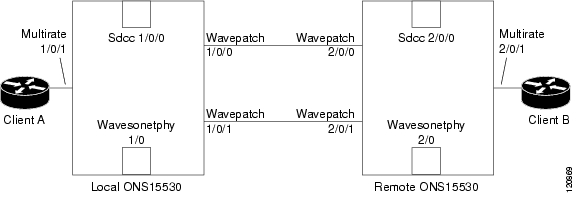
Figure 7-6 shows an example of 8-port multi-serve muxponders connected end-to-end. The following procedure describes the process of troubleshooting protocol level errors (for example, CRC errors on a Fastethernet interface) using loopbacks. Assume that the trunk connection between wavepatch 1/0/0 and wavepatch 2/0/0 is active.

Figure 7-6 8-Port Multi-Service Muxponders in an End-to-End Configuration


Step 1 Issue a loopback facility command on multirate interface 1/0/1 of client A. Verify that traffic comes back to client A without errors. If errors are seen, one of the following may be the cause:

Client A itself is sending traffic with errors.

The optical connectors between client A and the local Cisco ONS 15530 are dirty or need to be replaced.

The SFP on the multirate interface is faulty.

If no errors occur, proceed to Step 2.

Step 2 Issue a no loopback facility command on multirate interface 1/0/1 of the local Cisco ONS 15530, and issue a loopback terminal command on wavesonetphy 1/0 of the local Cisco ONS 15530. If errors occur, replace the 8-port multi-service muxponder. If no errors occur, proceed to Step 3.

Step 3 Issue a no loopback terminal command on wavesonetphy 1/0 of the local Cisco ONS 15530 and issue a loopback facility command on wavesonetphy 2/0 on the remote Cisco ONS 15530. If errors are seen on client A, one of the following may be the cause:

The optical connectors between the local Cisco ONS 15530 and the remote Cisco ONS 15530 are dirty or need to be replaced.

The 8-port multi-service muxponder on the remote Cisco ONS 15530 is faulty.

If no errors occur, proceed to Step 4.

Step 4 Issue a no loopback facility command on wavesonetphy 2/0 of the remote Cisco ONS 15530, and issue a loopback terminal command on multirate 2/0/1 on the remote Cisco ONS 15530. If errors are seen on client A, replace the 8-port multi-service muxponder in the remote Cisco ONS 15530. If no errors occur, proceed to Step 5.

Step 5 Issue a loopback facility command on multirate 2/0/1 of the remote Cisco ONS 15530. If errors are seen at client B the optical connectors between client B and the remote Cisco ONS 15530 are dirty or need to be replaced.


Note This procedure can also be used to troubleshoot traffic not flowing in an end-to-end scenario.


hometocprevnextglossaryfeedbacksearchhelp

Posted: Mon Apr 30 14:19:58 PDT 2007
All contents are Copyright © 1992--2007 Cisco Systems, Inc. All rights reserved.
Important Notices and Privacy Statement.