|
|

Table Of Contents
Troubleshooting 4-Port 1-Gbps/2-Gbps FC Aggregation Card Problems
5.2 Initial Troubleshooting Checklist
5.3 Troubleshooting 4-Port 1-Gbps/2-Gbps FC Aggregation Card Interface Problems
5.3.1 FC/FICON Encapsulated Twogigabitphy Interface Is Down
5.3.2 Twogigabitphy Interface Is Administratively Down
5.3.3 Client Equipment Interface Connected to the 4-Port 1-Gbps/2-Gbps FC Aggregation Card Is Not Up
5.3.4 Client Equipment Detects CVRD Errors
5.3.5 Transmit Frame Count Is Not Incrementing
5.3.6 FC/FICON Encapsulated Twogigabitphy Interface Receives CRC Errors from Trunk Card
5.3.7 Both the Local and Remote Twogigabitphy Interfaces Are Down
5.3.8 Twogigabitphy Interface Not Created
5.3.9 Twogigabitphy Interface Reports Loss of Sync
5.3.11 Throughput Is Asymmetric
5.3.12 Flow Control Is Inactive
5.3.13 Oversubscribed Portgroup and Superportgroup Related Problems Are Experienced
5.4 Troubleshooting Problems Using show controller Command Output
5.5 Troubleshooting 4-Port 1-Gbps/2-Gbps FC Aggregation Card Problems Using Loopbacks
Troubleshooting 4-Port 1-Gbps/2-Gbps FC Aggregation Card Problems
This chapter describes how to troubleshoot 4-port 1-Gbps/2-Gbps FC ( Fibre Channel) aggregation card interface problems. This chapter includes the following sections:
•
Overview
•
•
•
•
5.1 Overview
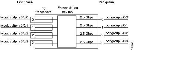
The 4-port 1-Gbps/2-Gbps FC aggregation card uses up to four SFP (small form-factor pluggable) optical transceivers to support client traffic. Each client interface can be configured using the CLI (command-line interface) for FC, FICON (fiber connection), or ISC (InterSystem Channel) traffic at a 1-Gbps or 2-Gbps rate.
The 4-port 1-Gbps/2-Gbps FC aggregation card connects four 2.5-Gbps electric signals, or portgroup interfaces, to the switch fabric. The client port data streams must be mapped to one of these portgroup interfaces, using the CLI. Only two 1-Gbps client interfaces or one 2-Gbps client interface can be mapped into a single portgroup interface.
The signal on the portgroup interfaces connects through the backplane and the switch fabric on the active CPU switch module to a 2.5-Gbps ITU trunk card, a 10-Gbps ITU trunk card, 10-Gbps ITU tunable trunk card, or a 10-Gbps uplink card, where the signal is converted to, and from, an ITU channel. The cross connections between the two cards through the backplane and switch fabrics are configured using the CLI.
The 1-Gbps client traffic from a 4-port 1-Gbps/2-Gbps FC aggregation card is compatible with the 8-port FC/GE aggregation card at the other end of the network. Any 1-Gbps FC, FICON, or ISC client signal can be transmitted between a 4-port 1-Gbps/2-Gbps FC aggregation card and an 8-port FC/GE aggregation card.
Figure 5-1shows an example path of a client signal through the Cisco ONS 15530 and the associated interfaces.
Figure 5-1 Interfaces for a 4-port 1-Gbps/2-Gbps FC Aggregation Card
5.2 Initial Troubleshooting Checklist
Follow this initial checklist before proceeding with the troubleshooting procedures:
•
•
•
•
•
•
•
–
–
–
•
•
5.3 Troubleshooting 4-Port 1-Gbps/2-Gbps FC Aggregation Card Interface Problems
This section contains troubleshooting procedures for 4-port 1-Gbps/2-Gbps FC aggregation card interface problems.
5.3.1 FC/FICON Encapsulated Twogigabitphy Interface Is Down
Symptom A twogigabitphy interface encapsulated for FC or FICON traffic is down because of Loss of Light.
Table 5-1 describes the potential causes of the symptom and the solutions.
5.3.2 Twogigabitphy Interface Is Administratively Down
Symptom A twogigabitphy interface is administratively down and cannot carry any type of traffic.
Table 5-2 describes the potential causes of the symptom and the solutions.
5.3.3 Client Equipment Interface Connected to the 4-Port 1-Gbps/2-Gbps FC Aggregation Card Is Not Up
Symptom The client equipment connected to a twogigabitphy interface is not up.
Table 5-3 describes the potential causes of the symptom and the solutions.
5.3.4 Client Equipment Detects CVRD Errors
Symptom The client equipment detects CVRD (code violation and running disparity) errors and the twogigabitphy interface shows Loss of Sync.
Table 5-4 describes the potential causes of the symptom and the solutions.
Table 5-4 Client Equipment Detects CVRD Errors
The protocol encapsulation configuration is incorrect.
Issue a show interfaces command for the twogigabitphy interface. Issue an encapsulation command if the protocol is incorrect.
The end-to-end speed negotiation configuration is incorrect.
Ensure that the speed of the client devices is set to auto or the same speed is configured on the client devices at both ends. The twogigabitphy interfaces must be locked to the same speed.
Tx CRC errors are reported on the twogigabitphy interface that is connected to an oversubscribed portgroup or superportgroup.
Ensure that the twogigabitphy interface of the 4-port 1-Gbps/2-Gbps FC aggregation card does not generate Tx CRC errors. For more information, refer to the "Oversubscribed Portgroup and Superportgroup Related Problems Are Experienced" section.
The connectors on the optical fiber between the client equipment and the SFP optics are dirty.
Refer to the Cisco ONS 15530 Cleaning Procedures for Fiber Optic Connections document.
5.3.5 Transmit Frame Count Is Not Incrementing
Symptom The Transmit Frame Count field in the show interfaces command output for the twogigabitphy interface is not incrementing.
Table 5-5 describes the potential causes of the symptom and the solutions.
Table 5-5 Transmit Frame Count Is Not Incrementing
An interface in the path is administratively shut down.
1.
2.
The client receive signal power is not strong enough.
1.
a.
b.
2.
a.
b.
c.
The cross connection is not properly configured.
1.
2.
3.
The flow identifier is not configured.
1.
2.
3.
5.3.6 FC/FICON Encapsulated Twogigabitphy Interface Receives CRC Errors from Trunk Card
Symptom A twogigabitphy interface encapsulated with either FC or FICON shows CRC (cyclic redundancy check) errors received from the trunk cards. The show interfaces command for the interface shows NO TX CRC.
Table 5-6 describes the potential cause of the symptom and the solution.
5.3.7 Both the Local and Remote Twogigabitphy Interfaces Are Down
Symptom The local twogigabitphy interface is down due to a local condition while the remote twogigabitphy interface is down due to a keepalive timeout.
Table 5-7 describes the potential cause of the symptom and the solution.
5.3.8 Twogigabitphy Interface Not Created
Symptom A twogigabitphy interface does not appear in the configuration and is not recognized by the system.
Table 5-8 describes the potential cause of the symptom and the solution.
5.3.9 Twogigabitphy Interface Reports Loss of Sync
Symptom The twogigabitphy interface reports Loss of Sync.
Table 5-9 describes the potential cause of the symptom and the solution.
For more information, refer to the "Oversubscribed Portgroup and Superportgroup Related Problems Are Experienced" section.
5.3.10 Throughput Is Low
Symptom Low throughput is experienced.
Table 5-10 describes the potential cause of the symptom and the solution.
Table 5-10 Throughput Is Low
After enabling end-to-end speed negotiation, the link has not negotiated to the 2 Gbps speed.
Ensure that the link has negotiated to the 2 Gbps speed.
For oversubscription or superportgroup configurations, flow control is not enabled at both ends.
Ensure that you enable flow control at both ends when oversubscription or superportgroup is configured.
For oversubscription or superportgroup configurations, flow control is not active at both ends.
Ensure that flow control is active at both ends when oversubscription or superportgroup is configured. For more information, refer to the "Flow Control Is Inactive" section.
The subrate and bandwidth lock configurations are not symmetrical at both ends.
Ensure that the subrate and bandwidth lock configurations are symmetrical at both ends.
If the problem persists, verify the throughput after locking the bandwidth at both ends, and then, if possible, after moving the oversubscibed link to a non-oversubscribed link. For more information, refer to the "Oversubscribed Portgroup and Superportgroup Related Problems Are Experienced" section.
5.3.11 Throughput Is Asymmetric
Symptom The throughput in one direction is greater than that in the other direction.
Table 5-11 describes the potential cause of the symptom and the solution.
5.3.12 Flow Control Is Inactive
Symptom Flow control is not in an active state.
Table 5-12 describes the potential cause of the symptom and the solution.
5.3.13 Oversubscribed Portgroup and Superportgroup Related Problems Are Experienced
Symptom Oversubscribed portgroup and superportgroup related problems are experienced.
Table 5-13 describes the potential cause of the symptom and the solution.
If the problem persists, continue troubleshooting after locking the bandwidth at both ends, and then, if possible, after moving the oversubscibed link to a non-oversubscribed link.
5.4 Troubleshooting Problems Using show controller Command Output
You can use the show controllers command output to determine and resolve problems on your 4-port 1-Gbps/2-Gbps FC aggregation card.
The following example shows the command output for the twogigabitphy interface:
Switch# show controllers twogigabitphy 4/0/0Controller info for interface TwoGigabitPhy4/0/0Line card base addr: 0x400000Optical Transceiver: Single Mode---------------------------------------------BPRX Channel Rx Frame count: 45478467BPTX Channel Tx Frame count: 45720664BPTX Channel Tx WORD count: 12871348901---------------------------------------------------TX CRC erro count: 0QDR CRC error count: 0QDR PARITY error count: 0Registers specific to client port 0:CONEY FPGA base addr: 0x60000Version.................: 0x6025A27Reset Control:Transmit (no), Receive (no)Loopback Control:Trunk (dis), CTC (dis)Send Pattern: NOSControl & Status:Auto Speed: (en), result (2g)Login State: (ELP_COMPLETE), Port State: (active)Port Encapsulation: (2xFC/FICON)Port Fail Registers(Cause -- UnMasked -- Enable -- Cur Status):SFP OIR: (no) -- (yes) -- (yes) -- (no)LINK FAIL: (yes) -- (yes) -- (yes) -- (no)TX FAULT: (no) -- (yes) -- (yes) -- (no)RX DEG: (no) -- (yes) -- (yes) -- (no)LOSS OF LIGHT: (no) -- (yes) -- (yes) -- (no)LOSS OF SYNC: (no) -- (yes) -- (yes) -- (no)Laser Control:Real Time KATO: (dis) Latched KATO: (en)OFC: (dis), BLC: (dis), FLC: (en)PHY CSR:loopback (dis), pre-emphasis (dis)SFP CSR:Present (yes), LOS (no), TXFAULT (no)Full Speed (yes), Laser Enabled (yes)OFC CSR:OFC on (no), OFC lineup (no)OFC laser ctrl (dis), OFC master (dis), OFC reset (en)Laser Enable Register:Shut reason: RT_KATO(no) LATCH_KATO(no) OFC(no) BLC(no) FLC(no)Laser WEN (no), Laser Software Enable (yes)Backware Laser Control RegisterReal Time Trigger: (no)Source: TXFAULT(yes) RXDEG(no) LOL(yes) LOSync(no)Forward Laser Control RegisterReal Time Trigger: (yes)Source: RXDEG(no) LOL(yes) LOSync(no)Tx LEDControlled by hardware (yes), software color (off)Rx LEDControlled by hardware (yes), software color (off)TX CVRD Error Count: 9, TX CRC Error Count: 3CVRD Rate Control:Threshold: 22149, Time 1000000 usecBPTX FPGA base addr: 0x50000Revision................: 0x5025A30Registers specific to client port 0:Memory Sharable: yes, Memory Size(0,1,2): 1Channel Reset: noCredit Management:en Flow Active: yesBP_LOGIN: no, BP_LOGI_DONE: yes, PORT_LOGI_DONE: yesEXCESS_CREDIT: no, LOCAL_FLOW: yes, REMOTE_FLOW: yesZERO_CREDIT: no, MEM_L_SIZE: 256, MEM_SIZE: 0x2000Egress FIFOAlmost Full Threshold: 6Almost Empty Threshold: 4KeepAliveControl: en, Time: 12775(us)Port Fail Registers(Cause -- UnMasked -- Enable -- Cur Status):FLOW INACTIVE: (no) -- (yes) -- (yes) -- (no)FIFO FULL: (no) -- (yes) -- (yes) -- (no)FIFO EMPTY: (no) -- (yes) -- (yes) -- (no)BDI-E: (no) -- (yes) -- (yes) -- (no)KeepAlive TimeOut: (no) -- (yes) -- (yes) -- (no)TxCRC Error: (no) -- (yes) -- (yes) -- (no)EXCESS FRAME: (no) -- (yes) -- (yes) -- (no)ECH TIMEOUT: (yes) -- (yes) -- (yes) -- (no)Tx CRCThreshold: 18846, Time: 1000000(us)BPRX FPGA base addr: 0x40000Revision................: 0x11104Registers specific to client port 0:Channel Reset: noChannel CSR:2G_Flag: dis, Port Map: 2, Port Enable: yesSubrate Percentage: 25 %, BW Share: noY-CABLE Register:FLC: en, BDIGEN: disBDI Mask and Control Register:Trunk RXF BDI: en, Client RXF BDI: dis, Client TXF BDI: enSTOP_KA: no, BDIGENST: no, BDIEBIT: en, AS1: 85SII: 255Flow Control Active to Inactive Transition count: 0Flow Control Inactive to Active Transition count: 0Oversubscription Available Credits: 944Flow Control Available Credits: 944Table 5-14 describes some of the fields in the show controllers twogigabitphy command output.
The following example shows the show controllers command output for the superportgroup interface:
Switch# show controllers superPortgroup 4/0/0Controller info for interface SuperPortgroup4/0/0Line card base addr: 0x400000---------------------------------------------------------------------------BANDWIDTH PORT Trunk StripingMAX ----------------- -------- ------------------Client RATE SII SRATE SHARE PC CRDT_SZ EN MAP Tk0 Tk1 Tk2 Tk3------ ---- --- ----- ----- --- ------- --- --- --- --- --- ---Port 2 212 255 187 yes 25 0x2000 yes 2 yes yes yes noPort 0 212 255 187 no 25 0x2000 yes 2 yes yes yes noPort 1 212 255 187 yes 25 0x2000 yes 2 yes yes yes noPort 3 212 255 187 yes 25 0x2000 yes 2 yes yes yes no-------------------------------------------------------------------------------------------------------------------------------Trunk SII CPU OVS TRUNK FILLER DROP SCRAMBLESHARE FRAMES CRC------ --- --- --- ----- ------ ---- --------Port 2 92 0 yes yes yes yes yesPort 1 91 0 yes yes yes yes yesPort 0 90 0 yes yes yes yes yes------------------------------------------------Table 5-15 describes some of the fields in the show controllers superportgroup command output.
The following example shows the show controllers command output for the portgroup interface:
Switch# show controllers Portgroup 9/0/1Controller info for interface Portgroup9/0/1Line card base addr: 0x700000BPTX FPGA base addr: 0x50000Revision................: 0x5025A30Registers specific to fabric port 1:Trunk Reset: noQGMII CSR:2nd CPU: no, LRCSWEN: yes, Active CPU: 0Descrambler: en, CRC Drop: enQGMII CVRDThreshold: 256, Time: 1000(us)Port Fail Registers(Cause -- UnMasked -- Enable -- Cur Status):CPU0 CVRD: (no) -- (yes) -- (yes) -- (no)CPU1 CVRD: (no) -- (yes) -- (yes) -- (no)BPRX FPGA base addr: 0x40000Revision................: 0x11104Registers specific to fabric port 1:Trunk Reset: noTrunk Loopback: disQGMII CSR:Scrambler: en Oversub: enTrunk Sharing: dis Filler Frames: disTrunk SII: 255 (Mib SII: 255)CHANNEL: 1-----------------------------------------------BPTX SII LUT 0x752400:0091 000002000092 00000400-------------------------------------------------------BANDWIDTH PORTMAX ----------------- --------Client RATE SII SRATE SHARE PC CRDT_SZ EN MAP------ ---- --- ----- ----- --- ------- --- ---Port 1 106 91 100 no 40 0x800 yes 1Port 2 212 92 150 no 60 0x2000 yes 1-------------------------------------------------------Table 5-16 describes some of the fields in the show controllers portgroup command output.
5.5 Troubleshooting 4-Port 1-Gbps/2-Gbps FC Aggregation Card Problems Using Loopbacks
This section describes how to use software loopbacks to perform fault isolation for signals on 4-port 1-Gbps/2-Gbps FC aggregation cards. The 4-port 1-Gbps/2-Gbps FC aggregation card supports two types of software loopbacks:
•
•
To perform further loopback operations, see the "8.4 Troubleshooting 2.5-Gbps ITU Trunk Card Problems Using Loopbacks" section on page 8-5, the "9.4 Troubleshooting 10-Gbps ITU Trunk Card Problems Using Loopbacks" section on page 9-5, and the "10.4 Troubleshooting 10-Gbps ITU Tunable Trunk Card Problems Using Loopbacks" section on page 10-6.
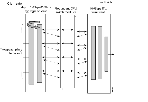
5.5.1 Facility Loopbacks
Facility loopbacks on 4-port 1-Gbps/2-Gbps FC aggregation cards verify the functioning of the SFP optics from the client side (see Figure 5-2).
Figure 5-2 Facility Loopback Example
Procedure: Create a Facility Loopback
Step 1
Step 2
Step 3
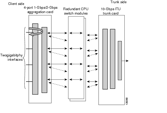
5.5.2 Terminal Loopbacks
Terminal loopbacks verify the functioning of the 4-port 1-Gbps/2-Gbps FC aggregation cards from the trunk side (see Figure 5-3).
Figure 5-3 Terminal Loopback Example
Procedure: Create a Terminal Loopback
Step 1
Step 2
Step 3
![]()
![]()
![]()
![]()
![]()
![]()
![]()
![]()
Posted: Mon Apr 30 13:37:48 PDT 2007
All contents are Copyright © 1992--2007 Cisco Systems, Inc. All rights reserved.
Important Notices and Privacy Statement.