|
|

Table Of Contents
Troubleshooting ESCON Aggregation Card Problems
4.2 Initial Troubleshooting Checklist
4.3 Troubleshooting ESCON Aggregation Card Interface Problems
4.3.1 Removing an SFP Optics Causes Alarms on Other Esconphy Interfaces
4.3.2 Shutting Down One Esconphy Interface Raises Alarms on Other Esconphy Interfaces
4.3.3 Reenabling an Esconphy Interface Clears Alarms on Other Esconphy Interfaces
4.3.5 Client Side Laser Unexpectedly Shuts Down
4.3.6 Client Traffic Does Not Flow End-to-End
4.3.7 Portgroup Interface Shows Continuous Errors
4.3.8 Esconphy Interface Not Created
4.4 Troubleshooting ESCON Aggregation Card Problems Using Loopbacks
Troubleshooting ESCON Aggregation Card Problems
This chapter describes how to troubleshoot ESCON aggregation card problems. This chapter includes the following sections:
•
Overview
•
•
•
4.1 Overview
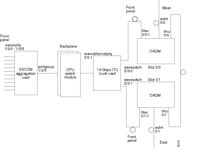
The ESCON aggregation card aggregates up to ten ESCON data streams into a single 2.5-Gbps signal, which is transmitted through the switch fabric to a 2.5-Gbps ITU trunk card, 10-Gbps ITU trunk card, 10-Gbps ITU tunable trunk card, or 10-Gbps uplink card. The ESCON aggregation card can be populated with up to ten SFP (small form-factor pluggable) optics.
Figure 4-1 shows an example path of an ESCON signal through the Cisco ONS 15530 and the associated interfaces.
Figure 4-1 Interface Model for ESCON Aggregation
4.2 Initial Troubleshooting Checklist
Follow this initial checklist before proceeding with the troubleshooting procedures:
•
•
•
•
•
•
•
•
4.3 Troubleshooting ESCON Aggregation Card Interface Problems
This section contains troubleshooting procedures for ESCON aggregation card interface problems.
4.3.1 Removing an SFP Optics Causes Alarms on Other Esconphy Interfaces
Symptom You removed one of the SFP optics on an ESCON aggregation card and alarm messages appear on the console for other interfaces on the same card.
Table 4-1 describes the potential cause of the symptom and the solution.
4.3.2 Shutting Down One Esconphy Interface Raises Alarms on Other Esconphy Interfaces
Symptom You shut down one esconphy interface and alarm messages appear on the console for other esconphy interfaces on the same ESCON aggregation card.
Table 4-2 describes the potential cause of the symptom and the solution.
4.3.3 Reenabling an Esconphy Interface Clears Alarms on Other Esconphy Interfaces
Symptom You issued a no shutdown command on one esconphy interface and alarm messages appear on the console for other esconphy interfaces on the same ESCON aggregation card.
Table 4-3 describes the potential cause of the symptom and the solution.
4.3.4 All Client Side Lasers Shut Down When Traffic to One Esconphy Interface Falls Below a Threshold
Symptom The client signal to one esconphy interface fell below an alarm threshold value which caused all client side lasers to shut down.
Table 4-4 describes the potential cause of the symptom and the solution.
4.3.5 Client Side Laser Unexpectedly Shuts Down
Symptom A client side laser unexpectedly shuts down without affecting other client side lasers on the ESCON aggregation card.
Table 4-5 describes the potential causes of the symptom and the solutions.
4.3.6 Client Traffic Does Not Flow End-to-End
Symptom The client traffic does not reach the remote system.
Table 4-6 describes the potential causes of the symptom and the solutions.
4.3.7 Portgroup Interface Shows Continuous Errors
Symptom A portgroup interface reports continuous errors to the system console.
Table 4-7 describes the potential causes of the symptom and the solutions.
Table 4-7 Portgroup Interface Shows Continuous Errors
A fault occurred in the switch fabric.
Issue a redundancy switch-activity command to switch over to the standby CPU switch module. If the switchover corrects the problem, replace the faulty CPU switch module.
A fault occurred in the ESCON aggregation card.
Perform signal loopbacks as described in the "Troubleshooting ESCON Aggregation Card Problems Using Loopbacks" section.
4.3.8 Esconphy Interface Not Created
Symptom A esconphy interface does not appear in the configuration and is not recognized by the system.
Table 4-8 describes the potential cause of the symptom and the solution.
4.4 Troubleshooting ESCON Aggregation Card Problems Using Loopbacks
This section describes how to use software loopbacks to perform fault isolation for signals on ESCON aggregation cards.
To perform further loopback operations, see the "8.4 Troubleshooting 2.5-Gbps ITU Trunk Card Problems Using Loopbacks" section on page 8-5, "10.4 Troubleshooting 10-Gbps ITU Tunable Trunk Card Problems Using Loopbacks" section on page 10-6, and the "9.4 Troubleshooting 10-Gbps ITU Trunk Card Problems Using Loopbacks" section on page 9-5.
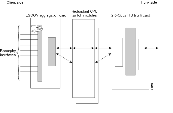
4.4.1 Client Signal Loopbacks
Client signal loopbacks on ESCON aggregation cards verify the functioning of the SFP optics (see Figure 4-2).
Figure 4-2 Client Signal Loopback Example
Procedure: Create a Client Signal Loopback
Step 1
Step 2
Step 3
![]()
![]()
![]()
![]()
![]()
![]()
![]()
![]()
Posted: Mon Apr 30 14:19:31 PDT 2007
All contents are Copyright © 1992--2007 Cisco Systems, Inc. All rights reserved.
Important Notices and Privacy Statement.