|
|

Table Of Contents
Troubleshooting Transponder Line Card Problems
3.2 Initial Troubleshooting Checklist
3.3 Troubleshooting Transponder Line Card Problems
3.3.1 Transponder Line Card Not in show hardware Command Output
3.3.2 Wave Interface Is Down and Shows Loss of Light
3.3.3 Transparent Interface Is Down and Shows Loss of Light
3.3.4 Active and Standby Wavepatch Interfaces Down Due to Loss of Light
3.3.5 Wave Interface Shows Loss of Lock
3.3.6 Transparent Interface Shows Loss of Lock
3.3.7 Interface Shows Loss of Sync
3.3.8 Interface Shows Loss of Frame
3.3.9 Active and Standby Wavepatch Interfaces Down Due to Low Alarm
3.3.10 Unable to Configure Protocol Encapsulation or Clock Rate
3.4 Troubleshooting Transponder Line Card Problems Using Loopbacks
Troubleshooting Transponder Line Card Problems
This chapter describes how to troubleshoot transponder line card problems. This chapter includes the following sections:
•
Overview
•
•
•
3.1 Overview
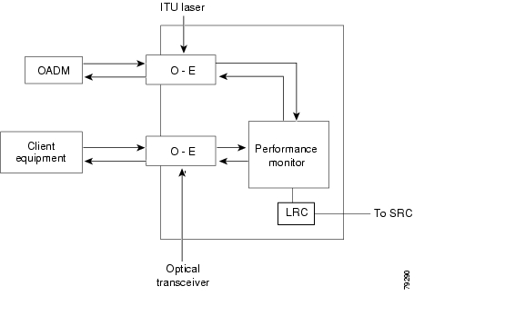
The protocol-transparent and bit-rate transparent transponder line card converts a client signal into an ITU wavelength, or channel. The transponder line cards have tunable lasers and you can configure the line cards to work in two different wavelengths.
The Cisco ONS 15530 supports four types of client interface transponder line cards: SM (single mode) unprotected, SM splitter protected, MM (multimode) unprotected, and MM splitter protected. Both types of SM transponder line cards accept SM client signals on the 1310-nm wavelength through an SC connector and support client signal clock rates ranging from 16 Mbps to 2.5 Gbps. Both types of MM transponder line cards accept SM and MM client signals on the 1310-nm wavelength through an SC connector and support client signal clock rates ranging from 16 Mbps to 622 Mbps.
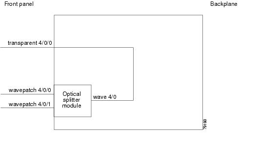
Figure 3-1 and Figure 3-2 show the architecture and the interfaces of the transponder line card.
Figure 3-1 Transponder Line Card Architecture
Figure 3-2 Transponder Line Card Interfaces
3.2 Initial Troubleshooting Checklist
Follow this initial checklist before proceeding with the troubleshooting procedures:
•
•
•
•
•
•
•
•
•
•
•
•
•
•
3.3 Troubleshooting Transponder Line Card Problems
This section contains troubleshooting procedures for transponder line card problems.
3.3.1 Transponder Line Card Not in show hardware Command Output
Symptom Transponder line card line is not listed in the show hardware command output.
Table 3-1 describes the potential causes of the symptom and the solutions.
3.3.2 Wave Interface Is Down and Shows Loss of Light
Symptom The wave interface is down and shows Loss of Light.
Table 3-2 describes the potential causes of the symptom and the solutions.
3.3.3 Transparent Interface Is Down and Shows Loss of Light
Symptom The transparent interface is down and shows Loss of Light.
Table 3-3 describes the potential causes of the symptom and the solutions.
3.3.4 Active and Standby Wavepatch Interfaces Down Due to Loss of Light
Symptom The active and standby wavepatch interfaces are down due to Loss of Light.
Table 3-4 describes the potential causes of the symptom and the solutions.
3.3.5 Wave Interface Shows Loss of Lock
Symptom The wave interface shows Loss of Lock.
Table 3-5 describes the potential causes of the symptom and the solutions.
3.3.6 Transparent Interface Shows Loss of Lock
Symptom The transparent interface shows Loss of Lock.
Table 3-6 describes the potential causes of the symptom and the solutions.
3.3.7 Interface Shows Loss of Sync
Symptom The wave or transparent interface shows Loss of Sync.
Table 3-7 describes the potential causes of the symptom and the solutions.
3.3.8 Interface Shows Loss of Frame
Symptom The wave or transparent interface shows Loss of Frame.
Table 3-8 describes the potential causes of the symptom and the solutions.
3.3.9 Active and Standby Wavepatch Interfaces Down Due to Low Alarm
Symptom The active and standby wavepatch interfaces are down due to low alarm.
Table 3-9 describes the potential causes of the symptom and the solutions.
3.3.10 Unable to Configure Protocol Encapsulation or Clock Rate
Symptom The CLI (command-line interface) rejects the protocol encapsulation or clock rate for the transparent interface.
Table 3-10 describes the potential cause of the symptom and the solution.
3.4 Troubleshooting Transponder Line Card Problems Using Loopbacks
This section describes how to use software loopbacks to perform fault isolation on the client and trunk interfaces of the transponder line cards.
Note
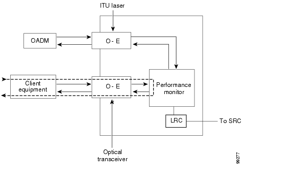
3.4.1 Client Signal Loopbacks
The client signal loopback verifies the continuity of the client signal path (see Figure 3-3).
Figure 3-3 Client Signal Loopback Example
Symptom Client signal loopback fails.
Table 3-11 describes the potential causes of the symptom and the solutions.
Procedure: Create a Client Signal Loopback
Step 1
Step 2
Step 3
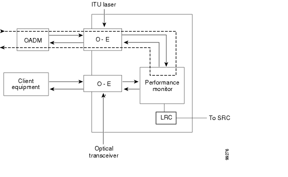
3.4.2 Trunk Loopbacks
The trunk loopback on a transponder line card verifies the configuration of the wave interface (see Figure 3-4).
Figure 3-4 Trunk Loopback Example
Symptom The trunk loopback fails.
Table 3-12 describes the potential causes of the symptom and the solutions.
Procedure: Create a Trunk Loopback
Step 1
Step 2
Step 3
![]()
![]()
![]()
![]()
![]()
![]()
![]()
![]()
Posted: Mon Apr 30 12:14:21 PDT 2007
All contents are Copyright © 1992--2007 Cisco Systems, Inc. All rights reserved.
Important Notices and Privacy Statement.