|
|

Table Of Contents
Installing the Cisco ONS 15530
Unpacking and Inspecting the Shelf
General Rack-Mount Installation Guidelines
Flush-Mounting the Cisco ONS 15530 CHAS-N in a 19-Inch Rack
Flush-Mounting the Cisco ONS 15530 CHAS-E in a 21-Inch Rack
Installing and Removing Line Cards or Motherboards
Installing Line Cards or Motherboards
Removing Line Cards or Motherboards
Installing SFPs into Aggregation Cards and Muxponders
Installing SFP with Mini SMB Coax Connectors
Removing SFP from Aggregation Cards and Muxponders
Installing and Removing Modules
Installing OADM Modules and PSMs
Installing OSC Modules, WB-VOA Modules, and PB-OE Modules
Power Connection Guidelines for DC-Powered Systems
Installing and Removing the Power Supplies
Installing the Cisco ONS 15530
This chapter describes the installation procedures for the Cisco ONS 15530 chassis and its components. This chapter includes the following sections:
•
Installing and Removing Line Cards or Motherboards
•
Note
Note
Before Installing
Before you install the Cisco ONS 15530, you must complete the following tasks:
•
•
•
•
Caution
Unpacking and Inspecting the Shelf
The Cisco ONS 15530 comes with the standard mounting set. The shelf is thoroughly inspected before shipment. If any damage has occurred during transportation or if any item is missing, notify your Cisco customer service representative immediately.
Upon receipt, inspect the equipment as follows:
Step 1
Compare the equipment inside with the packing slip and the equipment list provided by customer service. If there are any discrepancies, notify the Customer Service Center.
Step 2
Visually check all components and immediately report any shipping damage to your customer service representative. Have the following information ready:
•
•
•
•
Keep a record of all of your hardware, configuration options, and network settings.
Mounting the Shelf
The unit is designed for rack-mounting in a cabinet rack. Use star-type lock washers on the rack screws to ensure a good conductive connection between the chassis and the rack. For information about installing the units in a customer cabinet, see the instructions from the cabinet manufacturer.
Chassis-Lifting Guidelines
The fully configured system weighs approximately 71 pounds. The chassis is not intended to be moved frequently. Before you install the system, ensure that your site is properly prepared so you can avoid having to move the chassis later to accommodate power sources and network connections.
Two or more people are required to lift the chassis. Each time you lift the chassis or any heavy object, follow these guidelines:
•
•
•
•
•
•
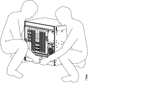
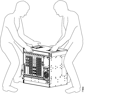
To safely lift the chassis, follow these steps:
Warning
Step 1
Step 2
Figure 2-1 Lifting the Cisco ONS 15530 CHAS-E
Figure 2-2 Lifting the Cisco ONS 15530 CHAS-N
Rack-Mounting the Shelf
Rack-mounting the shelf is the preferred method of installation for the Cisco ONS 15530. This section gives general rack-mount installation guidelines and explains how to install the rack-mount and cable-management brackets on the Cisco ONS 15530 for the following types of installations:
•
•
•
General Rack-Mount Installation Guidelines
When planning your rack-mount installation, consider the following guidelines:
•
Note
•
•
•
Caution
Caution
•
•
•
•
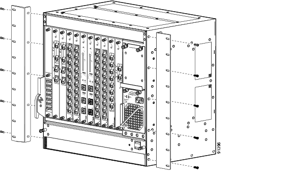
Flush-Mounting the Cisco ONS 15530 CHAS-N in a 19-Inch Rack
The Cisco ONS 15530 CHAS-N can be flush-mounted in a 19-inch equipment rack using the rack-mounting kit provided with your system. The rack-mounting kit contains the following parts:
•
•
•
Note
Warning
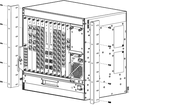
To flush-mount the Cisco ONS 15530 CHAS-N chassis in a 19-inch equipment rack, follow these steps :
Step 1
Step 2
Step 3
Figure 2-3 Attaching Mounting Brackets to Shelf
Figure 2-4 Attaching Shelf to Equipment Rack
Step 4
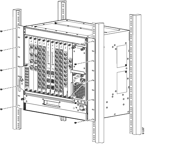
Flush-Mounting the Cisco ONS 15530 CHAS-E in a 21-Inch Rack
The Cisco ONS 15530 CHAS-E can be flush-mounted in a 21-inch equipment rack using the rack-mounting kit provided with your system. The rack-mounting kit contains the following parts:
•
•
Caution
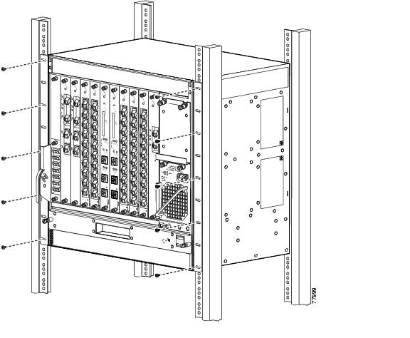
To flush-mount the Cisco ONS 15530 CHAS-N chassis in a 19-inch equipment rack, use the following steps:
Step 1
Step 2
Step 3
Figure 2-5 Attaching Mounting Brackets to Shelf
Figure 2-6 Attaching Shelf to Equipment Rack
Step 4
Step 5
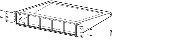
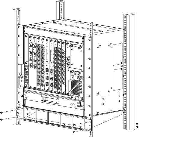
Attaching the Air Ramp Baffle
The air ramp baffle redirects the intake of cooling air from directly below, to the front of the Cisco ONS 15530 CHAS-E chassis, while deflecting hot exhaust air from equipment installed below.
To attach the air ramp baffle to the Cisco ONS 15530 CHAS-E chassis, follow these steps:
Step 1
Figure 2-7 Air Ramp Baffle Mounting Brackets
Step 2
Step 3
Figure 2-8 Installing the Air Ramp Baffle
Installing the Fiber Routing Management System
The fiber routing management system contains two main components; the cable routing tray and the cable routing drawer. The fiber routing tray is installed directly over the fan assembly, and the fiber routing drawer is installed below the Cisco ONS 15530 chassis. (See Figure 2-9.)
Figure 2-9 Fiber Management System
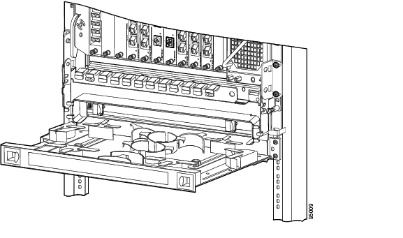
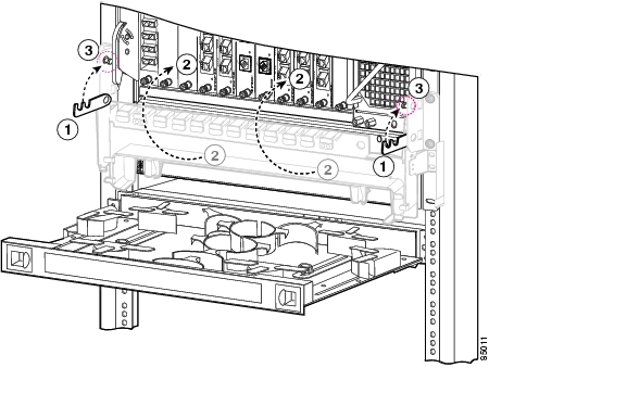
Installing the Fiber Routing Tray
To install the fiber routing tray, follow these steps:
Step 1
Figure 2-10 Raising the Fiber Routing Tray
Step 2
Step 3
Step 4
Step 5
Installing the Fiber Routing Drawer
To install the fiber routing drawer, follow these steps:
Step 1
Step 2
Step 3
Grounding the Shelf
Two system (earth) grounding holes are provided under the power supplies at the bottom right of the shelf.
Shelf Grounding Guidelines
To make an adequate grounding connection, you need the following parts and tools:
•
•
•
•
•
•
Note
Shelf Grounding Procedures
This section describes how to connect the Cisco ONS 15530 to earth ground. You must complete this procedure before connecting system power or powering up your shelf.
To ground the shelf, follow these steps:
Step 1
Figure 2-11 Attaching the Grounding Wire to Grounding Lug
Step 2
Step 3
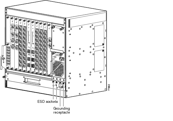
Step 4
Figure 2-12 Cisco ONS 15530 ESD Sockets
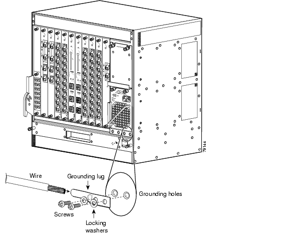
Step 5
Figure 2-13 Installing the Grounding Lug
Step 6
Step 7
Step 8
Note
Preventing ESD Damage
Electrostatic discharge (ESD) damage occurs when electronic cards or components are mishandled and can result in complete or intermittent failures. Note the following guidelines before you install or service the system:
•
•
•
•
Note
Installing and Removing Line Cards or Motherboards
The line cards and modules used on the Cisco ONS 15530 are hot-swappable. This section describes the procedures for installing and removing the following line cards and motherboards from the chassis:
•
•
•
•
•
•
•
•
•
•
•
Installing Line Cards or Motherboards
To install a line card or motherboard, follow these steps:
Step 1
Step 2
Step 3
Step 4
Step 5
Step 6
Removing Line Cards or Motherboards
To remove a line card or motherboard, follow these steps:
Step 1
Step 2
Step 3
Step 4
Step 5
Step 6
Installing SFPs into Aggregation Cards and Muxponders
To install SFPs into the ESCON aggregation cards, 8-port FC/GE aggregation cards, and 8-port multi-service muxponders, follow these steps:
Step 1
Step 2
Step 3
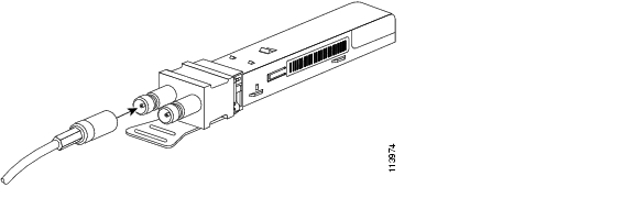
Installing SFP with Mini SMB Coax Connectors
To install the 15500-XVRA-10E1SFP with mini SMB coax connectors into the 8-port multi-service muxponder, follow these steps:
Step 1
Step 2
Note
Figure 2-14 Installing the 15500-XVRA-10E1 SFP
Step 3
Step 4
Tip
Removing SFP from Aggregation Cards and Muxponders
The SFPs used on the aggregation cards and muxponders have different types of connectors. The different connector types on the SFP optics are:
•
•
•
•
Each connector requires a different method of removal.
Note
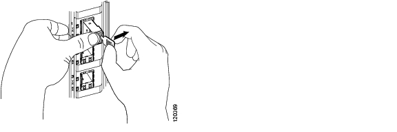
Removing Pull Tab SFPs with RJ-45 Connectors
To remove an SFP with an RJ-45 connector from the muxponder, follow these steps:
Step 1
Step 2
Step 3
Step 4
Figure 2-15 Releasing the SFP
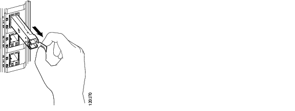
Step 5
Figure 2-16 Removing the SFP
Tip
Note
Removing Non-Pull Tab SFPs with RJ-45 Connectors
To remove an SFP with an RJ-45 connector from the muxponder, follow these steps:
Step 1
Step 2
Step 3
Note
Removing SFP Optics with MT-RJ Connectors
Note
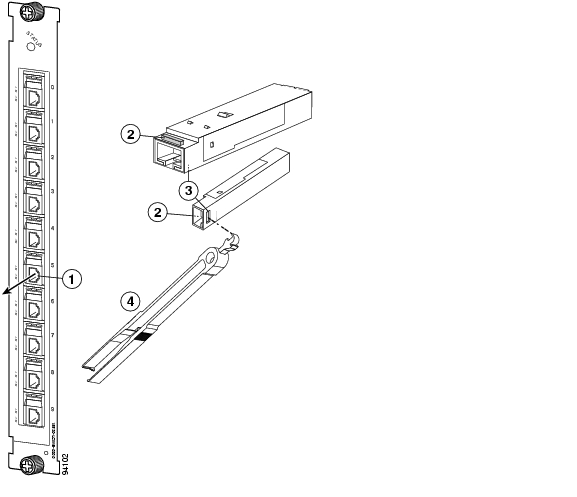
To remove an SFP with an MT-RJ connector from the ESCON aggregation card, follow these steps:
Step 1
Step 2
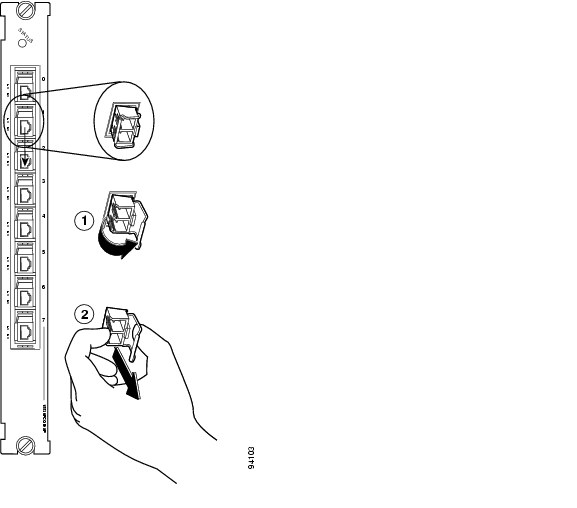
Figure 2-17 Removing the SFP with MT-RJ Connector
SFP placement in the module
Hole where the SFP extraction end of the tool is inserted (two views)
Lever on the SFP (two views)
SFP extraction and cable installation and removal tool
Step 3
Step 4
Removing SFP Optics with LC Connectors
To remove an SFP with an LC connector from the 8-port FC/GE aggregation card, follow these steps:
Step 1
Step 2
Figure 2-18 Removing the Transceiver with the LC Connector
Step 3
Step 4
Removing SFPs with Mini SMB Coax Connectors
To remove the 15500-XVRA-10E1 SFP with mini SMB coax connectors(MINISMB/BNC=) from the 8-port multi-service muxponder, follow these steps:
Step 1
Step 2
Step 3
Step 4
Note
Step 5
Step 6
Step 7
Installing and Removing Modules
The modules used on the Cisco ONS 15530 are hot-swappable. This section describes the procedures for installing and removing the OADM (optical add drop multiplexing) module, the PSM (protection switch modules), the OSC (optical supervisory channel) module, the WB-VOA (wide-band variable optical attenuator) module, and the PB-OE (per-band power equalizer) module.
Warning
Installing OADM Modules and PSMs
Slot 0 of the Cisco ONS 15530 chassis holds half height OADM modules and PSMs.
To install an OADM module or PSM, follow these steps:
Step 1
Step 2
Step 3
Step 4
Step 5
Installing OSC Modules, WB-VOA Modules, and PB-OE Modules
Up to two OSC modules can be installed in the carrier motherboard, one module for the west direction and one for the east direction. The WB-VOA module and PB-OE module are also installed in the carrier motherboard.
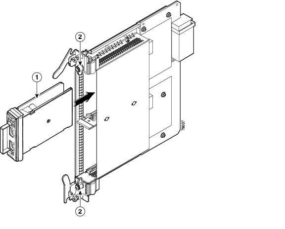
To install the OSC module, the WB-VOA module, or the PB-OE module, follow these steps:
Step 1
Step 2
Step 3
Step 4
Figure 2-19 Module Insertion in Carrier Motherboard
Step 5
Step 6
Save the filler modules with the packaging material.
Removing Modules
Warning
Warning
To remove a module from the Cisco ONS 15530 without interrupting system operation, follow these steps:
Step 1
Step 2
Step 3
Step 4
Step 5
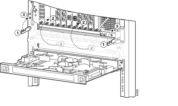
Replacing the Fan Assembly
To replace the fan assembly in the Cisco ONS 15530, follow these steps:
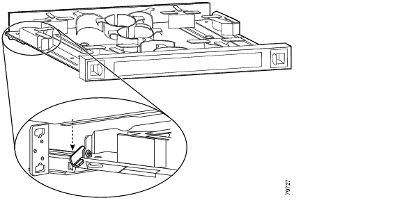
Step 1
Step 2
Figure 2-20 Drawer Lock
Step 3
Figure 2-21 Loosening the Cables
Step 4
Step 5
Figure 2-22 Hooking the Cable Management Tray
Step 6
Step 7
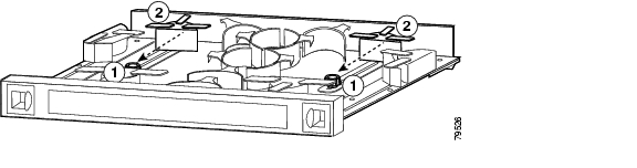
Step 8
Step 9
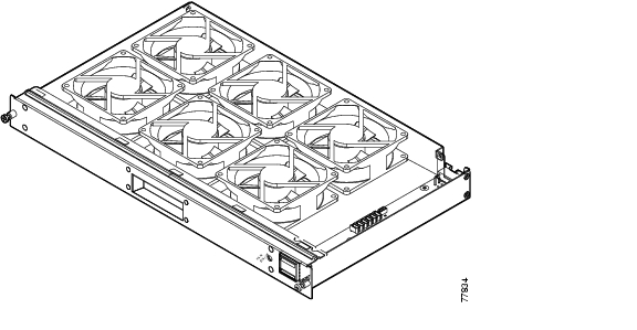
Figure 2-23 Fan Assembly
Step 10
Step 11
Step 12
Step 13
Power Guidelines
Follow these precautions and recommendations when planning power connections to the Cisco ONS 15530:
•
•
Caution
Note
Power Connection Guidelines for DC-Powered Systems
The DC-input power supply allows the Cisco ONS 15530 to operate at -48 VDC nominal in North America and -60 VDC in Europe.
See Appendix A, "Specifications," for system power specifications, including input voltage and operating frequency ranges.
Note
Warning
Warning
Plant Wiring Guidelines
Following are guidelines for setting up the plant wiring and cabling at your site. When planning the location of the new system, consider the distance limitations for signaling, EMI, and connector compatibility, as described in the following sections.
Interference Considerations
When wires are run for any significant distance in an electromagnetic field, interference can occur between the field and the signals on the wires. This fact has two implications for the construction of plant wiring:
•
•
Note
If you use twisted-pair cable in your plant wiring with a good distribution of grounding conductors, the plant wiring is unlikely to emit radio interference. If you exceed the recommended distances, use a high-quality twisted-pair cable with one ground conductor for each data signal when applicable.
If wires exceed recommended distances, or if wires pass between buildings, give special consideration to the effect of a lightning strike in your vicinity. The electromagnetic pulse caused by lightning or other high-energy phenomena can easily couple enough energy into unshielded conductors to destroy electronic devices. If you have had problems of this sort in the past, you may want to consult experts in electrical surge suppression and shielding.
Cabling Guidelines
The size of your networks and the distances between connections depend on the type of signal, the signal speed, and the transmission media (the type of cabling used to transmit the signals). For example, standard coaxial cable has a greater channel capacity than twisted-pair cabling. The distance and rate limits in the following descriptions are the IEEE recommended maximum speeds and distances for signaling; however, you can usually get good results at speeds and distances far greater than these. For example, the recommended maximum rate for V.35 is 2 Mbps, but it is commonly used at 4 Mbps without any problems. If you understand the electrical problems that might arise and can compensate for them, you should get good results with rates and distances greater than those shown here; however, do so at your own risk.
When preparing your site for network connections to the Cisco ONS 15530, you must consider a number of factors related to each type of interface:
•
•
•
•
Before you install the Cisco ONS 15530, have all additional external equipment and cables on hand. For ordering information, contact a customer service representative.
The extent of your network and the distances between network interface connections depend in part on the following factors:
•
•
•
The distance and rate limits referenced in the following sections are the IEEE-recommended maximum speeds and distances for signaling purposes. Use this information as a guideline in planning your network connections prior to installing the Cisco ONS 15530.
Powering Up the Shelf
System power is supplied by redundant -48 VDC or by redundant 120-240 VAC power supplies located on the right side of the chassis. The Cisco ONS 15530 supports the use -48 VDC and 120-240 VAC power supplies used together to provide redundancy.
Connecting DC-Input Power
Warning
Warning
To apply DC-input power to your Cisco ONS 15530, follow these steps:
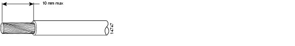
Step 1
Figure 2-24 Stripping Insulation
Step 2
Note
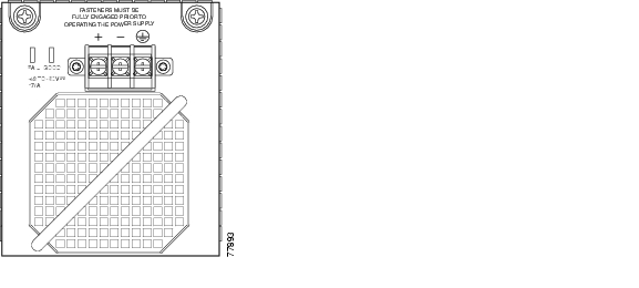
Step 3
Figure 2-25 DC Power Supply
Step 4
Step 5
Connecting AC-Input Power
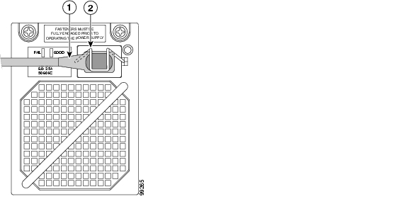
The Cisco ONS 15530 can be powered directly from the facility VAC input through the Cisco ONS 15530 120-240 VAC power supply (see Figure 2-26). A retention clip secures the power cord to the power supply.
Figure 2-26 120-240 VAC Power Supply
Note
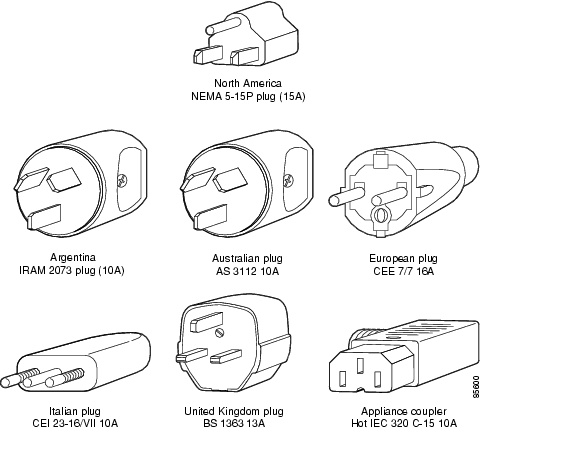
The AC-input power supply differ in plug type; make sure you have the correct style for your site (see Figure 2-27 and Table 2-1.) All AC-input power supply power cords measure 8 feet (2.5 m). We recommend that you:
•
•
Figure 2-27 AC Power Cords
Table 2-2 lists the nominal and acceptable value ranges for source AC power.
Installing and Removing the Power Supplies
To install an AC or DC power supply, follow these steps:
Step 1
Step 2
Step 3
Step 4
Step 5
To power on the chassis, see the "Powering Up the Shelf" section.
To remove an AC or DC power supply, follow these steps:
Step 1
Note
Step 2
Step 3
![]()
![]()
![]()
![]()
![]()
![]()
![]()
![]()
Posted: Fri Jun 2 04:42:26 PDT 2006
All contents are Copyright © 1992--2006 Cisco Systems, Inc. All rights reserved.
Important Notices and Privacy Statement.