|
|

Table Of Contents
Connecting the Cisco ONS 15530
Preparing for Network Connections
Cleaning the Shelf and Connectors
Connecting the CPU Switch Module
Ethernet Network Management Cable Connections
Connecting a Terminal to the Console Port
Connecting the Transponder Line Card
Connecting the ESCON Aggregation Card
Connecting the 4-Port 1-Gbps/2-Gbps FC Aggregation Card
Connecting the 8-Port FC/GE Aggregation Card
Connecting the 8-Port Multi-Service Muxponder
Connecting the 2.5-Gbps ITU Trunk Card
Connecting the 10-Gbps ITU Tunable and Non tunable Trunk Card
Connecting the 10-Gbps Uplink Card
Connecting the WB-VOA and PB-OE Modules
WB-VOA Attenuation on the Receive Side
PB-OE on the Trunk to Equalizing Add Channel Power to Pass Through Power
Using PB-OE Modules to Terminate Unused Bands
Connecting the Cisco ONS 15530
The Cisco ONS 15530 uses RJ-45, SC, MT-RJ and MU connectors on the faceplates of the line cards and modules. Fiber optic cables are routed to the cable management guides that are at the top and bottom of the shelf. The Cisco ONS 15530 is powered by 120-240 VAC or -48 VDC power. Positive, negative, and ground power terminals are accessible on the front of the chassis.
This chapter describes how to connect the Cisco ONS 15530 to the network and contains the following sections:
•
Preparing for Network Connections
•
•
•
•
•
•
•
•
•
•
•
•
Note
Note
Connector Types
Various types of connectors are used to connect the line cards and modules of the Cisco ONS 15530 to each other and the Internet. Table 3-1 lists the connector types used on each line card and module. Figure 3-1 through Figure 3-4 show the connector types.
Table 3-1 Line Card and Module Connector Types
CPU switch module
RJ-45 ( Figure 3-1)
OSC module
MU ( Figure 3-4)
Transponder line card
MU ( Figure 3-4), SC-Type ( Figure 3-2)
OADM module
MU ( Figure 3-4)
4-Port 1-Gbps/2-Gbps FC aggregation card
MU ( Figure 3-4)
8-Port FC/GE aggregation card
MU ( Figure 3-4)
ESCON aggregation card
MT-RJ ( Figure 3-3)
10-Gbps ITU tunable and non tunable trunk card
MU ( Figure 3-4)
10-Gbps uplink line card
SC-Type ( Figure 3-2)
WB-VOA module
MU ( Figure 3-4)
PB-OE module
MU ( Figure 3-4)
PSM
MU ( Figure 3-4)
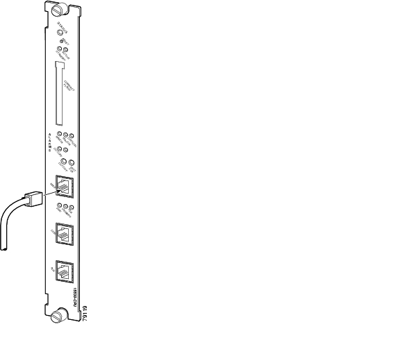
Figure 3-1 RJ-45 Connector
Figure 3-2 Simplex SC-Type Connector
Figure 3-3 MT-RJ Connector
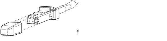
Figure 3-4 MU Connector
Preparing for Network Connections
When preparing your site for network connections to the Cisco ONS 15530, consider the following for each type of interface:
•
•
•
Before installing the component, have all additional external equipment and cables on hand.
Cleaning the Shelf and Connectors
If the cleaning process must be done while the system is running, be aware that the airflow system is in operation. Be careful of the following:
•
•
•
Warning
Fiber optic connectors are used to connect two fibers together. When these connectors are used in a communication system, proper connection becomes a critical factor. Fiber optic cable connectors can be damaged by improper cleaning and connection procedures. Dirty or damaged fiber optic connectors can result in not repeatable or inaccurate communication.
Fiber optic connectors differ from electrical or microwave connectors. In a fiber optic system, light is transmitted through an extremely small fiber core. Because fiber cores are often 62.5 microns or less in diameter, and dust particles range from a tenth of a micron to several microns in diameter, dust and any contamination at the end of the fiber core can degrade the performance of the connector interface where the two cores meet. Therefore, the connector must be precisely aligned and the connector interface must be absolutely free of trapped foreign material.
Connector, or insertion, loss is a critical performance characteristic of a fiber optic connector. Return loss is also an important factor. It specifies the amount of reflected light; the lower the reflection the better the connection. The best physical contact connectors have return losses better than -40 dB, although -20 to -30 dB is more common.
The connection quality depends on two factors: the type of connector and the proper cleaning and connection techniques. Dirty fiber connectors are a common source of light loss. Keep the connectors clean at all times and keep the dust cover installed when not in use.
Before installing any type of cable or connector, refer to Cisco ONS 15530 Cleaning Procedures for Fiber Optic Connections.
When cleaning fiber components, procedures must be followed precisely and carefully with the goal of eliminating any dust or contamination. A clean component connects properly; a dirty component may transfer contamination to the connector, or it may even damage the optical contacts. Inspecting, cleaning, and re-inspecting are critical steps that must be done before making any fiber connection.
As a general rule, whenever there is a significant, unexplained loss of light, clean the connectors.
Caution
Connecting the CPU Switch Module
The CPU switch module has three RJ-45 ports on the front of the card. This section provides the procedures for making the following connections:
•
•
•
Keep the following guidelines in mind when connecting external cables to the Cisco ONS 15530:
•
•
Ethernet Network Management Cable Connections
The CPU switch module provides an Ethernet port to a LAN for a 10BASE-T or 100BASE-T connection for network management. Use the following procedures to connect the Cisco ONS 15530 to an Ethernet network.
Note
Connecting to a 10BASE-T Ethernet Network
To make A 10BASE-T Ethernet connection, you need the following additional equipment (not included with your Cisco ONS 15530):
•
•
–
–
You can identify a straight-through Ethernet cable either by using a cable tester or by making a visual inspection. To make a visual inspection, hold the two ends of a cable side by side, with the tab for each at the back.
•
•
To connect the CPU switch module to a 10BASE-T Ethernet LAN, follow these steps:
Step 1
Figure 3-5 Connecting 10BASE-T to Ethernet Port
Step 2
Step 3
This LED is green if the CPU switch module is correctly connected to the 10BASE-T Ethernet LAN.
Connecting to a 100BASE-T Ethernet Network
To make a 100BASE-T Ethernet connection, you need the following additional equipment (not included with your Cisco ONS 15530):
•
•
–
–
You can identify a straight-through Ethernet cable either by using a cable tester or by making a visual inspection. To make a visual inspection, hold the two ends of a cable side by side, with the tab for each at the back.
•
•
Note
The port labeled NME on the CPU switch module is configurable for 100-Mbps full-duplex or half-duplex operation (half-duplex is the default) and supports IEEE 802.3, Ethernet, and IEEE 802.3u interfaces compliant with 100BASE-T specifications.
To connect the CPU switch module to a 100BASE-T Ethernet LAN, follow these steps:
Step 1
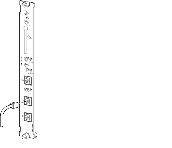
Figure 3-6 Connecting 100BASE-T to Ethernet Port
Step 2
Step 3
This LED is green if the CPU switch module is correctly connected to the 100BASE-T Ethernet LAN.
Connecting a Terminal to the Console Port
The Cisco ONS 15530 CPU switch module has an asynchronous serial (EIA/TIA-232) RJ-45 console port labeled CON on its front panel. You can connect this port to most types of terminals through use of the console cable kit that is included with your Cisco ONS 15530. The console cable kit contains:
•
•
•
A crossover cable reverses pin connections from one end to the other. In other words, it connects pin 1 (at one end) to pin 8 (at the other end), pin 2 to pin 7, pin 3 to pin 6, and so on. You can identify a crossover cable by comparing the two modular ends of the cable. Hold the cable ends in your hand, side-by-side, with the tabs at the back. Ensure that the wire connected to the outside (left) pin of the left plug (pin 1) is the same color as the wire connected to the outside (right) pin of the right plug (pin 8).
To connect a terminal to the console port on a CPU switch module, follow these steps:
Note
Step 1
Figure 3-7 Console Port Connection on the CPU Switch Module
Step 2
•
•
Figure 3-8 Connecting an RJ-45-to-DB-9 Console Cable Adapter
Step 3
Step 4
Step 5
•
•
•
•
•
Auxiliary Modem Connection
This asynchronous EIA/TIA-232 serial port connects a modem to the CPU switch module for remote administrative access.
To connect the Cisco ONS 15530 to a modem, follow these steps:
Step 1
Figure 3-9 Connecting Modem Cable to Auxiliary Port
Step 2
Connecting the OSC Module
One or two OSC modules can be installed in the carrier motherboard. When two OSC modules are installed, one module is for the west direction and one is for the east direction.
The OSC modules are connected to the OADM modules before they terminate on a neighboring node. To install the OSC cables proceed as follows:
Step 1
Figure 3-10 OSC Module Cable Connections
Step 2
Step 3
Figure 3-11 Dual OSC Module Cable Connections
Connecting the PSM
The PSM (protection switch module) is a shelf replaceable unit that plugs into one of the OADM subslots in the shelf. The unit has a front panel set of MU connectors that interface with the trunk fiber in a 1+1 protection scheme.
To install fiber optic cables in the Cisco ONS 15530, a fiber cable with the corresponding connector type must be connected to the transmit and receive ports on the modules. We recommend that you label the transmit, receive, and the working and protection fibers at each end of the fiber span to avoid confusion with cables that are similar in appearance. Labels are shipped with the system.
Warning
Note
Cabling PSMs
To attach and route fiber optic cables for the PSM and OADM module, follow these steps:
Step 1
Figure 3-12 PSM Cable Connections
Step 2
Step 3
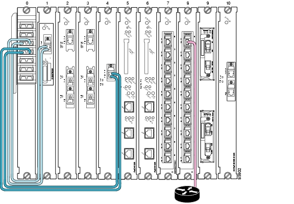
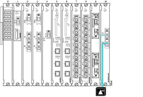
The PSM supports direct connections from the ITU trunk cards, transponder line cards, and 10-Gbps uplink cards. Figure 3-13 shows a the PSM directly connected to a 2.5-Gbps ITU trunk card.
Figure 3-13 PSM Cabled to a 2.5-Gbps ITU Trunk Card
To connect the PSM, follow these steps:
Step 1
Step 2
Step 3
Connecting the Transponder Line Card
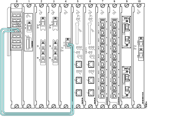
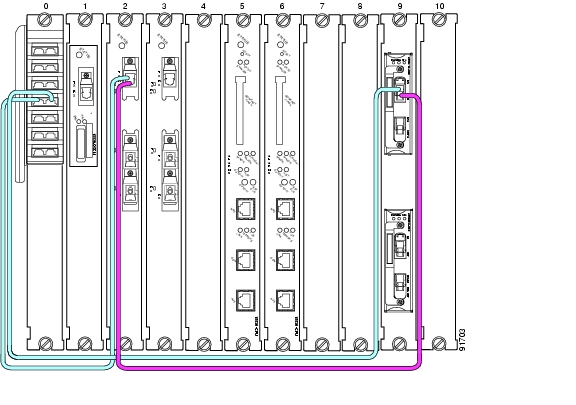
The transponder line card receives a single client signal, converts it into an ITU wavelength or channel, and sends it to the OADM module. Figure 3-14 shows the cable connections in an unprotected configuration. The ITU transmit port of the transponder line card is connected to the Coexists IN port of the OADM module and the ITU receive port is connected to the Coexists OUT port. The client side transmit and receive ports on the transponder line card are connected to the client router.
Figure 3-14 Transponder Line Card Cable Connections (Unprotected)
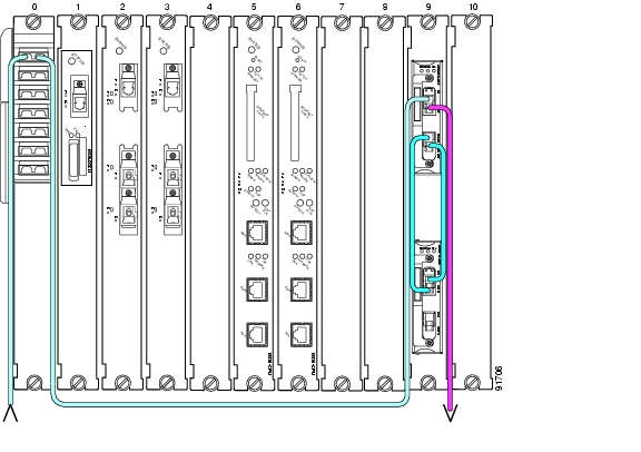
In a splitter configuration the connections are the same, with the addition of a second set of ITU ports on the transponder line card. In a splitter configuration the two sets of ITU ports are labeled WEST and EAST and two OADM modules are required. Figure 3-15 shows the cable connections in a splitter configuration.
Figure 3-15 Transponder Line Card Cable Connections (Splitter)
Connecting the OADM Module
The OADM module takes signals from the transponder line cards and the 10-Gbps ITU trunk cards, multiplexes the signals, and puts the multiplexed signal on the network. In the reverse direction, the OADM modules demultiplexes incoming signals and sends them to the transponder line cards and the 10G ITU line cards. See the "Connecting the PSM" section and the "Connecting the 10-Gbps ITU Tunable and Non tunable Trunk Card" section for specific information on these connections.
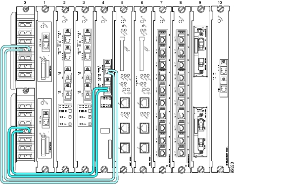
Figure 3-16 shows the OADM module network connections in a splitter configuration. The TRUNK_IN and TRUNK_OUT ports of the first OADM module are connected to the west side trunk. The TRUNK_IN and TRUNK_OUT ports of the second OADM module are connected to the east side trunk. In addition the MID_IN port of the first OADM module is connected to the MID_OUT port of the second OADM module, and the MID_OUT port of the first OADM module is connected to the MID_IN port of the second OADM module.
Figure 3-16 OADM Module Trunk Cable Connections
Connecting the ESCON Aggregation Card
The ESCON aggregation card converts up to 10 client signals from optical to electrical and aggregates them into a single 2.5-Gbps signal. The aggregated signal is then sent through the backplane and the active switch fabric to either a 2.5-Gbps ITU trunk card, 10-Gbps ITU trunk card, or a 10-Gbps uplink line card. Figure 3-17 shows the connections.
Note
Figure 3-17 ESCON Aggregation Card Cable Connections (Unprotected)
Connecting the 4-Port 1-Gbps/2-Gbps FC Aggregation Card
The 4-port 1-Gbps/2-Gbps FC aggregation card accepts up to four Cisco-certified SFP (small form-factor pluggable) optics for client traffic. Each SFP supports Fibre Channel, FICON, or ISC depending on how it is configured in the CLI. The 4-port 1-Gbps/2-Gbps FC aggregation card converts client signals from optical form to electrical form, and then aggregates them into four 2.5-Gbps signals over the backplane. These aggregated signals pass through the backplane and the switch fabric on the active CPU switch module to a 2.5-Gbps ITU trunk card, a 10-Gbps ITU trunk card, or a 10-Gbps uplink card. The cross connections between the two cards through the backplane and switch fabric are configured using the CLI. The 4-port 1-Gbps/2-Gbps FC aggregation card has redundant connections over the backplane to the switch fabric on the active and standby CPU switch modules. Figure 3-18 shows the connections.
Figure 3-18 4-port 1-Gbps/2-Gbps FC Aggregation Card Cable Connections
The Cisco ONS 15530 supports up to four 4-port 1-Gbps/2-Gbps FC aggregation cards for a total of 16 unprotected and protected client signals and up to three 4-port 1-Gbps/2-Gbps FC aggregation cards for 12 protected client signals.
The 4-port 1-Gbps/2-Gbps FC aggregation cards is configurable on a single port basis. The SFPs enable this card to support four Fibre channel, FICON, or ISC interfaces running at full speed. The card has four ports on the client side and four 2.5-GE lanes on the trunk side.
The 4-port 1-Gbps/2-Gbps FC aggregation card uses single-mode and multimode SFPs for the client signals. There are no restrictions on populating the line card with SFPs. For example, you can mix a single-mode SFP optic with a multimode SFP optic.
Note
Connecting the 8-Port FC/GE Aggregation Card
The 8-port FC/GE aggregation card accepts up to eight Cisco-certified SFP (small form-factor pluggable) optics for client traffic. Each SFP supports either FC, FICON, GE or ISC, depending on how it is configured in the CLI. The 8-port FC/GE aggregation card converts client signals from two adjacent port pairs (0-1, 2-3, 4-5, or 6-7) from optical form to electrical form, and then aggregates them into four 2.5-Gbps signals over the backplane. These aggregated signals pass through the backplane and the switch fabric on the active CPU switch module to a 2.5-Gbps ITU trunk card, a 10-Gbps ITU trunk card, or a 10-Gbps uplink card. The cross connections between the two cards through the backplane and switch fabric are configured using the CLI. The 8-port FC/GE aggregation card has redundant connections over the backplane to the switch fabric on the active and standby CPU switch modules. Figure 3-19 shows the connections.
Figure 3-19 8-Port FC/GE Aggregation Card Cable Connections
Note
The Cisco ONS 15530 supports up to four 8-port FC/GE aggregation cards for a total of 32 unprotected client signals and up to three 8-port FC/GE aggregation cards for 24 protected client signals.
The 8-port FC/GE aggregation card is configurable on a single port basis. The SFPs enable this card to support eight Fibre channel or Gigabit Ethernet interfaces running at full speed. The card has eight ports on the client side and four 2.5-GE lanes on the trunk side.
The 8-port FC/GE aggregation card uses single-mode and multimode SFP optics for the client signals. There are no restrictions on populating the line card with SFPs. For example, you can mix a single-mode SFP optic with a multimode SFP optic in the same port pair.
Note
Connecting the 8-Port Multi-Service Muxponder
The 8-port multi-service muxponder accepts up to eight Cisco-certified SFPs for client traffic. Each SFP supports different protocols that can be aggregated and transported ranging from high-speed services such as Fibre Channel and Gigabit Ethernet to low-speed services such as OC-3, Fast Ethernet, T1, or E1, depending on how it is configured in the CLI. The 8-port multi-service muxponder is configurable on a single port basis. The Cisco ONS 15530 supports up to four 8-port multi-service muxponders for a total of 32 unprotected client signals and up to three 8-port multi-service muxponders for 24 protected client signals. Figure 3-20 shows the possible connections.
Figure 3-20 8-Port Multi-Service Muxponder Cable Connections
Note
Connecting the 2.5-Gbps ITU Trunk Card
The 2.5-Gbps ITU trunk card has three redundant interfaces to the backplane that pass signals to and from the line cards. The optical ports on the front of the line card are connected to the OADM module. The TX port of the 2.5-Gbps ITU trunk card is connected to the CHxxxIN port of the OADM module and the RX port is connected to the CHxxxOUT port. Figure 3-21 shows these connections in an unprotected configuration.
Figure 3-21 2.5-Gbps ITU Trunk Card Cable Connections (Unprotected)
Figure 3-22 shows these connections in a splitter configuration. The WEST port connections go to the first OADM module and the EAST port connections go to the second OADM module.
Figure 3-22 2.5-Gbps ITU Trunk Card Cable Connections (Splitter)
Connecting the 10-Gbps ITU Tunable and Non tunable Trunk Card
The 10-Gbps ITU trunk card, both tunable and non tunable, has four separate redundant interfaces to the backplane that passes signals to and from the line cards. The optical ports on the front of the line card are connected to the OADM module. The TX port of the 10-Gbps ITU trunk card is connected to the CHxxxIN port of the OADM module and the RX port is connected to the CHxxxOUT port. Figure 3-23 show these connections in an unprotected configuration.
Figure 3-23 10-Gbps ITU Tunable or Non tunable Trunk Card Cable Connections (Unprotected)
Figure 3-24 shows these connections in a splitter configuration. The WEST port connections go to the first OADM module and the EAST port connections go to the second OADM module.
Figure 3-24 10-Gbps ITU Tunable or Non tunable Trunk Card Cable Connections (Splitter)
Connecting the 10-Gbps Uplink Card
The 10-Gbps uplink card sends and receives a 10-GE 1310-nm signal to and from a 10-GE transponder module on a Cisco ONS 15540 ESP or Cisco ONS 15540 ESPx. This card accepts up to four 2.5-Gbps (3.125-Gbps line rate) electrical signals from ESCON line cards and combines them into a 10-GE signal. This signal is converted to a 1310 nm wavelength signal. Figure 3-25 shows the cable connections.
Figure 3-25 10-Gbps Uplink Line Card Cable Connections
Connecting the WB-VOA and PB-OE Modules
The WB-VOA and PB-OE modules allow the Cisco ONS 15530 to extend the inter-nodal and ring circumference distances, and to extend the number of nodes supported for hubbed ring, and meshed ring networks by equalizing power levels. The WB-VOA and PB-OE modules can be configured in several ways.
This section includes the following topics:
•
•
•
Per-Channel Equalization
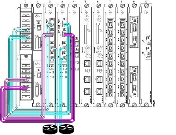
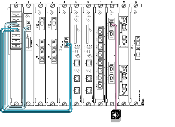
Figure 3-26 shows an example of per-channel equalization in an unprotected configuration. In this example, the WB-VOA is the top module in slot 9.
Figure 3-26 Per Channel Equalization (Unprotected)
Note
To install the cables, follow these steps:
Step 1
Step 2
Step 3
Note
(See Figure 1-16 on page 1-21).WB-VOA Attenuation on the Receive Side
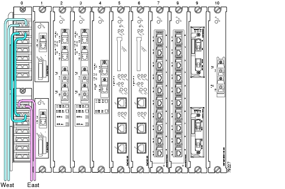
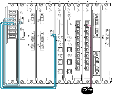
The WB-VOA module can be connected on the receive side to attenuate the signal. Figure 3-27 shows an example of WB-VOA attenuation on the receive side in an unprotected configuration. In this example, the WB-VOA is the top module in slot 9.
Figure 3-27 WB-VOA Attenuation on the Receive Side (Unprotected)
To install the cables, follow these steps:
Step 1
Step 2
Step 3
Note
(See Figure 1-16 on page 1-21).WB-VOA on the Trunk
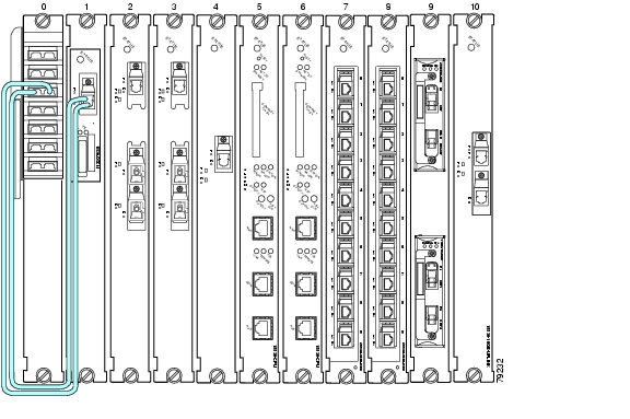
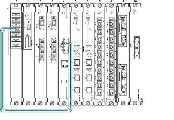
The WB-VOA module can be connected to attenuate the trunk signal leaving the node. Figure 3-28 shows an example of these cable connections on an unprotected configuration. In this example, the WB-VOA is the bottom module in slot 9.
Figure 3-28 WB-VOA on Trunk (TX Side)
To connect the WB-VOA on the trunk, follow these steps:
Step 1
Step 2
Step 3
Note
PB-OE on the Trunk to Equalizing Add Channel Power to Pass Through Power
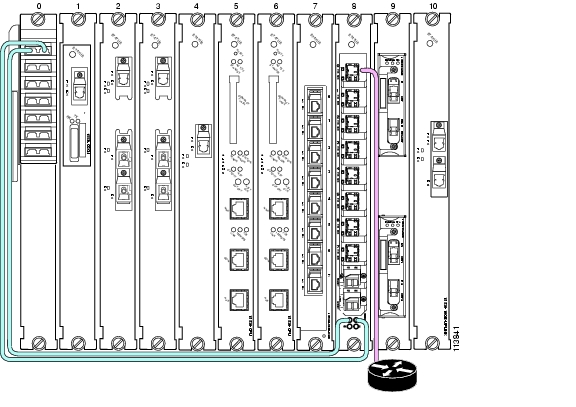
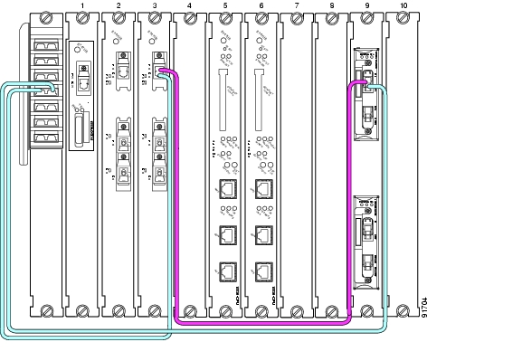
The PB-OE provides per-band attenuation on the trunk. Figure 3-29 shows an example of an unprotected configuration of a PB-OE module cabled on the trunk. In this example, the PB-OE is the top module in slot 9, and the WB-VOA is the bottom module in slot 9.
Figure 3-29 PB-OE on the Trunk (Unprotected)
To install the cables in an unprotected configuration, follow these steps:
Step 1
Step 2
Step 3
Step 4
Step 5
Note
Using PB-OE Modules to Terminate Unused Bands
PB-OE modules can be used to equalize power and terminate unused bands, eliminating potential lasing effects. This configuration is also known as an optical seam. Place optical seams in meshed ring topologies where there are no nodes equivalent to the hub node in a hubbed ring topology where all the used and unused bands terminate. Be sure to have PB-OE modules in the optical seam to equalize every added band on the network.
Figure 3-30 shows an example of two PB-OE modules configured to equalize bands E, F, G and H and terminate the unused bands in the west to east direction only. The east to west direction can be configured on any node.
Figure 3-30 Using PB-OE Modules to Terminate Unused Bands
To install the cables in this configuration, follow these steps:
Step 1
Step 2
Step 3
Step 4
Step 5
Step 6
Step 7
Note
Connecting a Multi-Shelf Node
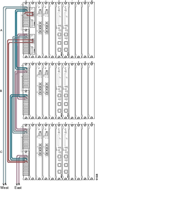
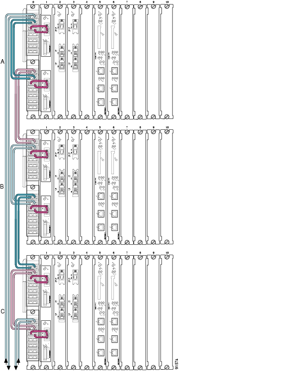
There are a number of ways to configure a multi-shelf node. Figure 3-31 and Figure 3-32 are two examples of how multi-shelf nodes can be connected. Figure 3-31 shows a configuration of cascaded OADMs which supports multiple bands in the node and Figure 3-32 shows a three shelf node with OSC modules that are added and dropped on each shelf.
Figure 3-31 Cascading the OADMs on a Multi-Shelf Node
Figure 3-32 Basic Cable Connections on a Multi-Shelf Node
To connect a three shelf node with cascaded OADMs, follow these steps:
Step 1
a.
b.
c.
Step 2
a.
b.
c.
d.
Step 3
a.
b.
Step 4
a.
b.
Step 5
Note
To connect a three shelf node in a splitter configuration where the OSC modules are added and dropped on each shelf, follow these steps:
Step 1
a.
b.
c.
d.
e.
Step 2
a.
b.
c.
d.
Step 3
a.
b.
c.
d.
Step 4
a.
b.
c.
d.
Step 5
a.
b.
c.
d.
Step 6
a.
b.
c.
Note
Cable Management
Due to the flexibility and complexity of configurations available with the Cisco ONS 15530, managing the placement and storage of the fiber optic cables is a must. To avoid confusion and ensure the integrity of the fiber optic cables used with the Cisco ONS 15530, we recommend that both ends of all fiber optic cables be labelled. Labels for this purpose are shipped with the system.
Note
The cable storage drawer provides the management system for the cabling. The following procedures describe how to connect the cables on your system.
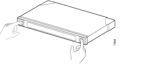
Step 1
Figure 3-33 Opening the Cable Storage Drawer
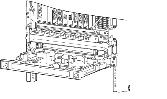
Step 2
Figure 3-34 Pulling out the Cable Storage Drawer
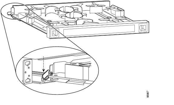
Step 3
Figure 3-35 Locking the Cable Storage Drawer Open
Step 4
Step 5
Step 6
Step 7
Step 8
Figure 3-36 Unlocking the Cable Storage Drawer
![]()
![]()
![]()
![]()
![]()
![]()
![]()
![]()
Posted: Wed May 31 10:16:10 PDT 2006
All contents are Copyright © 1992--2006 Cisco Systems, Inc. All rights reserved.
Important Notices and Privacy Statement.