|
|

Table Of Contents
OSC Modules and Carrier Motherboards
Wide-Band Variable Optical Attenuator and Per-Band Optical Equalizer Modules
4-Port 1-Gbps/2-Gbps FC Aggregation Cards
8-Port FC/GE Aggregation Cards
8-Port Multi-Service Muxponders
10-Gbps ITU Tunable Trunk Cards
Cisco ONS 15530 Overview
The Cisco ONS 15530 is a modular and scalable optical switching and aggregation platform designed to supplement the Cisco ONS 15540 ESP. With the Cisco ONS 15530, users can take advantage of the availability of dark fiber to build a common infrastructure that supports data, storage area network (SAN), and time-division multiplexing(TDM) traffic. For more information about DWDM technology and applications, refer to the Introduction to DWDM Technology publication and the
Cisco ONS 15530 Planning Guide.The Cisco ONS 15530 is designed to meet or exceed stringent ISP (Internet service provider) requirements for product availability and reliability.
Note
Before you install, operate, or service the system, read the Regulatory Compliance and Safety Information for the Cisco ONS 15500 Series for important safety information you should know before working with the system.
This chapter includes the following sections:
Cisco ONS 15530 Chassis
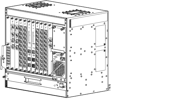
The Cisco ONS 15530 is available in two configurations. Both have two vertically stacked half-height slots specifically for the optical OADM (optical add/drop multiplexing) modules, and 10 vertically oriented slots that hold the CPU switch modules, line cards, and 2.5-G transponder trunk line cards. Slot 0 holds two half height optical OADM modules. Slots 1 through 4 and slots 7 through 10 hold the line cards and transponder cards. Slots 5 and 6 hold the CPU switch modules. Power supplies are located on the right side of the chassis next to slot 10. Air inlet and fan tray assembly are located beneath the slots. Cable management is located beneath the slots. The system has an electrical backplane for system control. All optical connections are located on the front of the cards. Figure 1-1 shows a fully populated chassis.
Figure 1-1 Cisco ONS 15530 Shelf
The chassis configurations differ in how cooling air is routed through the chassis and where the lifting handles are placed.
Cisco ONS 15530-CHAS-E Chassis
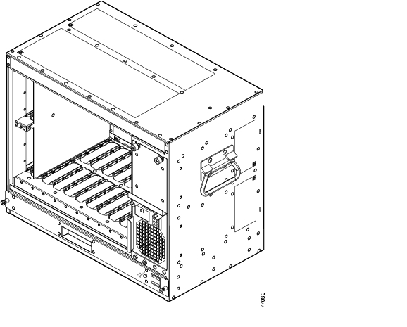
The dimensions of the Cisco ONS 15530 CHAS-E chassis are 14.4 x 17.3 x 10.1 inches (H x W x D) See Figure 1-2. Handles for lifting the chassis are located on the sides.
Figure 1-2 Cisco ONS 15530 CHAS-E Chassis
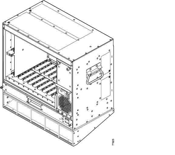
The fan assembly draws in cooling air through the air ramp baffle (see Figure 1-3) on the bottom of the chassis, pushing the air across the internal components and out the exhaust baffles on the top of the chassis.
The air ramp baffle for the Cisco ONS 15530 CHAS-E chassis redirects the cooling air intake as shown in Figure 1-4. The air ramp baffle must be installed when installing the Cisco ONS 15530 CHAS-E type chassis.
Figure 1-3 Cisco ONS 15530 CHAS-E (with Air Ramp Baffle)
Figure 1-4 Cisco ONS 15530 CHAS-E Chassis Airflow (with Air Ramp Baffle Installed)
Cisco ONS 15530 CHAS-N Chassis
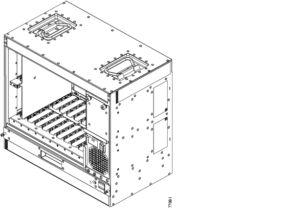
The dimensions of the Cisco ONS 15530 CHAS-N chassis are 14.4 x 15.7 x 10.1 inches (H x W x D). (See Figure 1-5.) Handles for lifting the chassis are located on the top. The fan assembly draws in cooling air through the intake baffles on the front of the chassis, below the fan assembly, pushing the air over the internal components and out the exhaust on the top rear and sides of the chassis (see Figure 1-6).
Figure 1-5 Cisco ONS 15530 CHAS-N Chassis
Figure 1-6 Cisco ONS 15530 CHAS-N Chassis Airflow
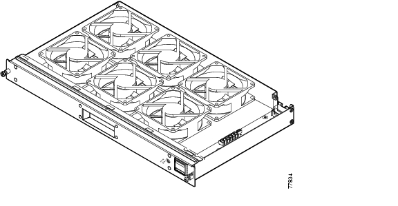
Fan Assembly
The Cisco ONS 15530 fan assembly is located at the bottom of the chassis. The assembly contains six individual fans and a fan controller board (see Figure 1-7).
Figure 1-7 Fan Assembly
The controller board monitors the status of each fan and reports the status to the CPU switch modules. If a single fan fails, a minor alarm is reported to the CPU and the fan assembly LED changes from green to yellow (see Figure 1-8). If two or more fans fail, a major alarm is reported to the CPU and the fan LED changes to red.
Figure 1-8 Fan Assembly LED
Table 1-1 lists the fan assembly LED status describing the alarm reports for the fan assembly. The fan assembly is hot-swappable.
Table 1-1 Fan Assembly Status
None
Green
Normal
One
Yellow
Minor
Two or more
Red
Major
Audible and Visible Alarms
The Cisco ONS 15530 provides audible and visible alarm status to the Telco central office alarm equipment through hardware located on the fan assembly (see Figure 1-8). Software determines the alarm condition and sets the appropriate relays for critical, major, or minor alarms. Table 1-2 lists the terminal block pinouts.
Table 1-2 Terminal Block Pinouts
P1
Visible
Critical
1
C1
Each type and level of alarm is signaled by a contact closure of C to NO and an open from C to NC.
Voltage at contacts is limited to 48 VDC.
Switched current / load is limited to 1-A resistive.
Alarms are signaled when the chassis is unpowered.
2
NC2
3
NO3
Major
4
C
5
NC
6
NO
Minor
7
C
8
NC
9
NO
P2
Audible
Critical
1
C
2
NC
3
NO
Major
4
C
5
NC
6
NO
Minor
7
C
8
NC
9
NO
1 C = center
2 NC = normally closed
3 NO = normally open
Power Supplies
The Cisco ONS 15530 chassis supports redundant 120-240 VAC (see Figure 1-9) or -48 VDC (see Figure 1-10) power. The power supplies are located at the right of the chassis, next to the card slots (see Figure 1-1). Up to two power supplies can be installed for redundancy.
Figure 1-9 120-240 VAC Power Supply
Figure 1-10 -48 VDC Power Supply
See the "Powering Up the Shelf" section on page 2-31 for more information about the power supplies.
Backplane
The Cisco ONS 15530 backplane implements all board-to-board signal interconnects and provides power distribution within the chassis. Connections are present for two power supplies and the fan assembly. The backplane contains a total of 12 slots; two half-height slots for the OADM modules, two full height slots for the CPU switch modules, and eight full height slots for line cards and transponder cards.
Cable Storage Drawer
The cable storage drawer is mounted directly below the fan assembly. It provides storage for the excess cable length. Sliding radius limiters move to release the excess fiber cable slack when the drawer is pulled out, allowing the user to raise the fiber routing tray and access the fan assembly.
Version Identification Labels
The version identifier on a 4-port 1-Gbps/2-Gbps FC aggregation card is located on the inside of the card. We reccommend that you record the version ID in a safe place before installing the card. You can also use the show hardware and show inventory commands to verify the version ID of the card.
Cisco ONS 15530 Components
The following hardware components can be installed in the Cisco ONS 15530:
•
•
•
•
•
•
•
Note
CPU Switch Modules
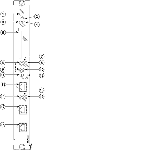
The Cisco ONS 15530 supports two CPU switch modules for redundancy, one in active mode and the other in hot-standby mode. CPU switch modules are installed in slot 5 and slot 6. Each CPU switch module has a processor, a switch fabric, a clock, an Ethernet switch for communication between processors and with the LRC (line card redundancy controller) on the OADM modules and line cards, and an SRC (switch card redundancy controller). The active processor controls the system. All LRCs in the system use the system clock and synchronization signals from the active processor. Interfaces on the CPU switch modules permit access by 10/100 Ethernet, console terminal, or modem connections.
Figure 1-11 shows the front panel of the CPU switch module.
Figure 1-11 Cisco ONS 15530 CPU Switch Module
CPU Switch Module Ports, LEDs, and Switches
Table 1-3 lists the LEDs on the CPU switch module faceplate with a description of the status indication.
Connector Ports
The front panel on the CPU switch module contains three ports with RJ-45 connectors (see Figure 1-11):
•
•
•
The RJ-45 connectors on the front panel of the CPU switch module have an extra EMI shield and the signals going to them are filtered.
Table 1-4 shows the pinouts of the console and auxiliary ports.
CompactFlash Card Slot
A CompactFlash card slot (see Figure 1-11) can store the Cisco IOS image or a system configuration file on a CompactFlash memory card. The system can also boot from the software stored on the CompactFlash memory card.
OSC Modules and Carrier Motherboards
The OSC (optical supervisory channel) module supports an optional out-of-band management channel for communicating between systems on the network. Using a 33rd wavelength (channel 0), the OSC allows control and management traffic to be carried without requiring a separate Ethernet connection to each Cisco ONS 15530 in the network. Up to two OSC modules can be installed in the carrier motherboard, one module for the west direction and one for the east direction.
The OSC always terminates on a neighboring node. By contrast, data channels may or may not be terminated on a given node, depending on whether the channels on the OADM modules are treated as either express (pass-through) or add/drop channels.
Figure 1-12 shows the front panel of the OSC module.
Figure 1-12 OSC Module
OSC Module LEDs
Table 1-5 lists the LEDs on the OSC module faceplate, their default conditions, and what the conditions indicate.
PSMs
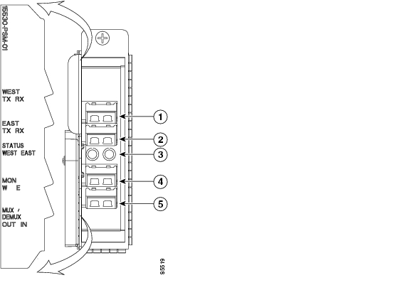
The PSM (protection switch module) provides trunk fiber protection for Cisco ONS 15530 systems configured in point-to-point topologies. The PSM sends the signal from an OADM module, an ITU trunk card, or a transponder line card to both the west and east directions. It receives both the west and east signals and sends to the OADM module, ITU trunk card, or transponder line card. Both nodes in the network topology must have the same shelf configuration.When a trunk fiber cut occurs on the active path, the PSM switches the received signal to the standby path. Because the PSM occupies one of the OADM subslots in the shelf, it protects a maximum of four channels and the OSC in a single shelf configuration.
The PSM also has an optical monitor port for testing the west and east receive signals. This port samples one percent of these signals, which can be monitored with an optical power meter or an optical spectrum analyzer.
A PSM can be installed in subslots 0/0 and 0/1 of the Cisco ONS 15530 chassis.
The PSM for the Cisco ONS 15530 has a front panel with four MU connector pairs, as shown in Figure 1-13.
Figure 1-13 PSM
Rx/Tx West ports
East and West optical monitor ports
Rx/Tx East ports
Common IN/OUT ports
East and West status LEDs
PSM LEDs
Table 1-6 lists the LEDs on the PSM faceplate, their default conditions, and what the conditions indicate.
Table 1-6 PSM LEDs
Status
Green
Software initialization is successful.
Off
Board failure.
Transponder Line Cards
The protocol-transparent and bit-rate transparent transponder line card converts a single client signal into an ITU wavelength, or channel. The transponder line cards have tunable lasers and you can configure the line cards to work in two different wavelengths. The Cisco ONS 15530 holds up to four transponder line cards, one for each wavelength supported by the OADM modules.
The Cisco ONS 15530 supports four types of single client interface transponder line cards: SM (single mode) unprotected, SM splitter protected, MM (multimode) unprotected, and MM splitter protected. Both types of SM transponder line cards accept SM client signals on the 1310-nm wavelength through an SC connector and support client signal clock rates ranging from 16 Mbps to 2.5 Gbps. Both types of MM transponder line cards accept SM and MM client signals on the 1310-nm wavelength through an SC connector and support client signal clock rates ranging from 16 Mbps to 622 Mbps (see Figure 1-14 and Figure 1-15).
Figure 1-14 Transponder Line Card LEDs (Nonsplitter)
Card status LED
Client side transmit LED
ITU side port
Client side transmit port
ITU transmit LED
Client side receive LED
ITU receive LED
Client side receive port
Figure 1-15 Transponder Line Card LEDs (Splitter)
The transponder line cards are hot swappable, permitting in-service upgrades and replacement. All client signals on the transponders are supported in 3R (reshape, retime, retransmit) mode, regardless of protocol encapsulation type. The client interfaces also support the OFC (open fiber control) safety protocol for Fibre Channel, ISC compatibility mode, and FICON. The client side ports use SC-type connectors.
On the trunk side, the transponder line card output laser power ranges from 5 to 10 dBm and the receive detector has a sensitivity of -32 dBm. The ports on the trunk side use MU-type connectors.
Transponder Line Card LEDs
Table 1-7 lists the LEDs on the transponder line card faceplate, their default conditions, and what the conditions indicate.
Table 1-7 Transponder Line Card LEDs
STATUS
Green
Card is properly initialized.
Blinking green
Good system clock is present and card is out of reset state.
Yellow
System clock is not present.
EAST1
Green
Card is listening to the east side signal.
TX (Trunk port)
Green
Port is up and transmit laser is enabled.
RX (Trunk port)
Green
Light reception exists at the port.
WEST 1
Green
Card is listening to the west side signal.
TX (Client port)
Green
Port is up and transmit laser is enabled.
RX (Client port)
Green
Light reception exists at the port.
1 This LED is only present on transponder line cards with splitter.
OADM Modules
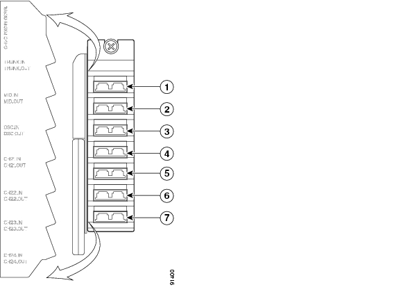
The OADM modules are passive devices that optically multiplex and demultiplex a specific band of four ITU wavelengths. The OADM modules supported by the Cisco ONS 15530 each add and drop a specified band of four channels at a node and pass the other bands through. To support the 32-channel spectrum, there are eight different 4-channel cards (see Figure 1-16).
In the transmit direction, the OADM modules multiplex signals transmitted by the transponder line cards and 10-Gbps ITU trunk cards over optical cross connections and provide the interfaces to connect the multiplexed signal to the DWDM trunk side. In the receive direction, the OADM modules demultiplex the signals from the trunk side before passing them over optical cross connections to the transponder line cards and 10-Gbps ITU trunk cards.
Figure 1-16 OADM Module
Trunk IN/OUT ports
Data channel IN/OUT ports
Thru IN/OUT ports
Data channel IN/OUT ports
OSC IN/OUT ports1
Data channel IN/OUT ports
Data channel IN/OUT ports
1 Only on OADM modules with OSC. These ports are not used on other modules.
Wide-Band Variable Optical Attenuator and Per-Band Optical Equalizer Modules
The WB-VOA (wide-band variable optical attenuator) and PB-OE (per-band power equalizer) modules are half-width modules that allow the ONS 15530 to extend the internodal and ring circumference distances and number of nodes supported for point-to-point, hub ring, and mesh ring networks by equalizing power levels.
The WB-VOA module and the PB-OE module are available in single and dual band versions. These modules are installed into a carrier motherboard. This motherboard is installed into and operates on the Cisco ONS 15530 chassis. The carrier motherboard can be installed in slots 1 to 4 or 7 to 10. All optical connectors are located on the front panel and the connectors are angled.
Figure 1-17 and Figure 1-18 show the single and dual versions of the WB-VOA module. Figure 1-19 and Figure 1-20 show the single-band and dual-band versions of the PB-OE module.
Figure 1-17 Single WB-VOA Module
Table 1-8 lists the LEDs on the single WB-VOA module faceplate, their default conditions, and what the conditions indicate.
Table 1-8 Single WB-VOA Module LEDs
PM1
Green
Light reception exists at the port.
STA
Green
Card is properly initialized.
Figure 1-18 Dual WB-VOA Module
Table 1-9 lists the LEDs on the dual WB-VOA module faceplate, their default conditions, and what the conditions indicate.
Table 1-9 Dual WB-VOA Module LEDs
PM2
Green
Light reception exists at the port.
PM1
Green
Light reception exists at the port.
STATUS
Green
Card is properly initialized.
Figure 1-19 Single-Band PB-OE Module
Table 1-10 lists the LEDs on the single-band PB-OE module faceplate, their default conditions, and what the conditions indicate.
Table 1-10 Single-Band PB-OE Module
PM1
Green
Light reception exists at the port.
STA
Green
Card is properly initialized.
Figure 1-20 Dual-Band PB-OE Module
Table 1-11 lists the LEDs on the dual-band PB-OE module faceplate, their default conditions, and what the conditions indicate.
Table 1-11 Dual-Band PB-OE LEDs
PM2
Green
Light reception exists at the port.
PM1
Green
Light reception exists at the port.
STATUS
Green
Card is properly initialized.
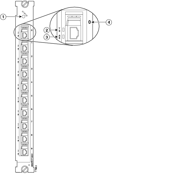
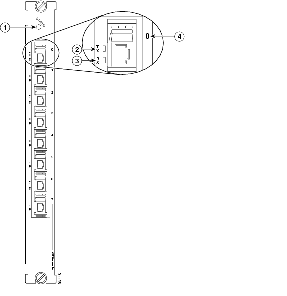
ESCON Aggregation Cards
The ESCON aggregation card is a 10-port card for ESCON (Enterprise Systems Connection) traffic. The ESCON card converts the 10 client signals from optical to electrical and then aggregates them into a single 2.5-Gbps signal. This aggregated signal is sent through the backplane and the active switch fabric to either a 10-Gbps ITU trunk card or a 10-Gbps uplink card. The cross connection between the two cards is configured using the CLI (command-line interface). The ESCON aggregation card has a redundant backplane connection.
The ESCON aggregation card uses multimode 62.5/125 Βm optical cable with SFPs (small form factor pluggables) and MT-RJ connectors for the client signals. (See Figure 1-21.)
Note
Figure 1-21 ESCON Aggregation Card
This signal is sent through the switch fabric to a 10-Gbps ITU trunk card or a 10-Gbps uplink card. The 10-Gbps ITU trunk card converts the aggregated signal to an ITU-compliant wavelength, or channel. The 10-Gbps uplink card converts the aggregated signal to transmit to another shelf.
Table 1-12 describes the ESCON aggregation card LED status.
The ESCON aggregation card uses single-mode and multimode SFP optics for the client signals. There are no restrictions on populating the line card with SFPs. For example, you can mix a single-mode SFP optics with a multimode SFP optics on the same ESCON aggregation card. Table 1-13 lists the characteristics for the SFP optics supported by the ESCON aggregation card.
Note
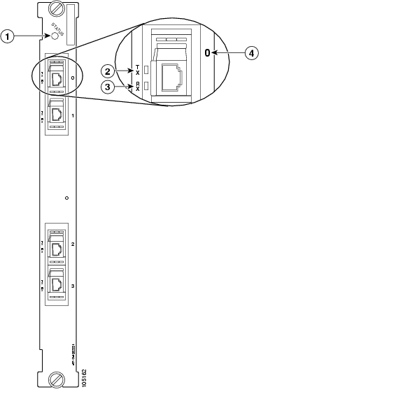
4-Port 1-Gbps/2-Gbps FC Aggregation Cards
The Cisco ONS 15530 supports a line card for FC (Fibre Channel), FICON, and ISC traffic. The 4-port 1-Gbps/2-Gbps FC aggregation card accepts up to four SFP (small form-factor pluggable) optics for client traffic. Each SFP optic supports either FC, FICON, or ISC, depending on how it is configured in the CLI. The 4-port 1-Gbps/2-Gbps FC aggregation card connects four 2.5-Gbps electric signals, or portgroup interfaces, to the switch fabric. The client port data streams must be mapped to one of these portgroup interfaces, using the CLI. Only two 1-Gbps client interfaces or one 2-Gbps client interface can be mapped into a single portgroup interface.The signal on the portgroup interfaces connects through the backplane and the switch fabric on the active CPU switch module to a 2.5-Gbps ITU trunk card, a 10-Gbps ITU trunk card, or a 10-Gbps uplink card, where the signal is converted to, and from, an ITU channel. The cross connections between the two cards through the backplane and switch fabrics are configured using the CLI. The 4-port 1-Gbps/2-Gbps FC aggregation card has redundant connections over the backplane to the switch fabric on the active and standby CPU switch modules. (See Figure 1-22).
Figure 1-22 4-Port 1-Gbps/2-Gbps FC Aggregation Card
Table 1-14 lists the LEDs on the 4-port 1-Gbps/2-Gbps FC aggregation card, their default conditions, and what the conditions indicate.
The 4-port 1-Gbps/2-Gbps FC aggregation card uses single-mode and multimode SFP optics for the client signals. There are no restrictions on populating the line card with SFPs. Table 1-15 lists the characteristics for the SFP optics supported by the 4-port 1-Gbps/2-Gbps FC aggregation card.
Table 1-15 4-port 1-Gbps/2-Gbps FC Aggregation Card SFP Optics Characteristics
15500-XVRA-02C1
Gigabit Ethernet1 , Fibre Channel (1 Gbps)2 , FICON (1 Gbps), ISC-1 (1-Gbps)
MM 50/125 Βm
MM 62.5/125 Βm850 nm
LC
15500-XVRA-03B1
Gigabit Ethernet3 , Fibre Channel (1 Gbps)4 , FICON (1 Gbps), ISC-3 links compatibility mode
SM 9/125 Βm
1310 nm
LC
15500-XVRA-03B2
Fibre Channel (1-Gbps and 2-Gbps), FICON (1-Gbps and 2 Gbps)
SM 9/125 Βm
1310 nm
LC
15500-XVRA-11B1
Mid-band variable rate 200-Mbps to 1.25-Gbps, ISC-1
SM 9/125 Βm
1310 nm
LC
15500-XVRA-12B1
High-band variable rate 1.062-Gbps to 2.488-Gbps, ISC-1, ISC-3
SM 9/125 Βm
1310 nm
LC
15454-SFP-GEFC-SX
Fibre Channel (2-Gbps), Fibre Channel (1-Gbps), FICON (1-Gbps and 2 Gbps)
ISC-3 (1-Gbps and 2 Gbps)MM 50/125 Βm
MM 62.5/125 Βm850 nm
LC
ONS-SE-GEFC-SX
Fibre Channel (2-Gbps), Fibre Channel (1-Gbps), FICON (1-Gbps and 2 Gbps)
ISC-3 (1-Gbps and 2 Gbps)MM 50/125 Βm
MM 62.5/125 Βm850 nm
LC
1 1000BASE-SX
2 FC-0-100-M5-SN-S and FC-0-100-M6-SN-S standards
3 1000BASE-LX
4 FC-0-100-SM-LC-S standard
8-Port FC/GE Aggregation Cards
The Cisco ONS 15530 supports a line card specifically for ISC (compatibility and peer mode), FICON, FC (Fibre Channel) and GE (Gigabit Ethernet) traffic. The 8-port Fibre Channel/Gigabit Ethernet aggregation card accepts up to eight SFP (small form-factor pluggable) optics for client traffic. Each SFP optic supports either FC or GE, depending on how it is configured in the CLI. The 8-port FC/GE aggregation card converts client signals from two adjacent port pairs (0-1, 2-3, 4-5, or 6-7) from optical form to electrical form, and then aggregates them into four 2.5-Gbps signals. These aggregated signals pass through the backplane and the switch fabric on the active CPU switch module to a 2.5-Gbps ITU trunk card, a 10-Gbps ITU trunk card, or a 10-Gbps uplink card. The cross connections between the two cards through the backplane and switch fabric are configured using the CLI. The 8-port FC/GE aggregation card has redundant connections over the backplane to the switch fabric on the active and standby CPU switch modules. (See Figure 1-23).
Figure 1-23 8-Port FC/GE Aggregation Card
Note
Note
The Cisco ONS 15530 supports up to four 8-port FC/GE aggregation cards for a total of 32 client signals.
Table 1-16 describes the LEDs on the 8-port FC/GE aggregation card.
The 8-port FC/GE aggregation card uses single-mode and multimode SFP optics for the client signals. There are no restrictions on populating the line card with SFPs. For example, you can mix a single-mode SFP optics with a multimode SFP optics on the same port pair. Table 1-17 lists the characteristics for the SFP optics supported by the 8-port FC/GE aggregation card.
Table 1-17 8-port FC/GE Aggregation Card SFP Optics Characteristics
15500-XVRA-02C1
Gigabit Ethernet1 , Fibre Channel (1 Gbps)2 , FICON (1 Gbps)
MM 50/125 Βm
MM 62.5/125 Βm850 nm
LC
15500-XVRA-03B1
Gigabit Ethernet3 , Fibre Channel (1 Gbps)4 , FICON (1 Gbps), ISC-3 links compatibility mode, ISC peer mode
SM 9/125 Βm
1310 nm
LC
15500-XVRA-11B1
Mid-band variable rate 200 Mbps to 1.25 Gbps
SM 9/125 Βm
1310 nm
LC
15500-XVRA-11B2
Mid-band variable rate 200 Mbps to 1.25 Gbps
SM 9/125 Βm
1310 nm
LC
15500-XVRA-12B1
High-band variable rate 1.062 Gbps to 2.488 Gbps
SM 9/125 Βm
1310 nm
LC
1 1000BASE-SX
2 FC-0-100-M5-SN-S and FC-0-100-M6-SN-S standards
3 1000BASE-LX
4 FC-0-100-SM-LC-S standard
Note
Protocol monitoring is the same as for single mode transponder modules and multimode transponder modules.
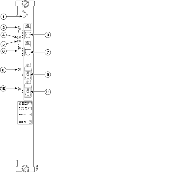
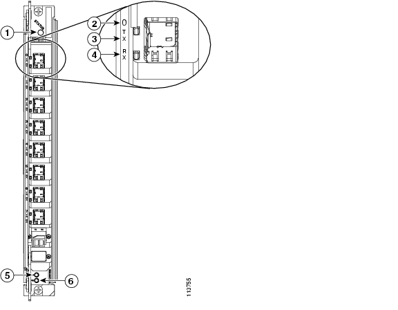
8-Port Multi-Service Muxponders
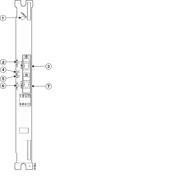
The 8-port multi-service muxponder aggregates up to eight ports of client traffic into 2.5-Gbps DWDM traffic to the trunk. The muxponder transports a mix of different protocols between sites in a metro DWDM network. The protocols that can be aggregated and transported range from high-speed services such as Fibre Channel and Gigabit Ethernet to low- speed services such as OC-3, Fast Ethernet, or even T1 or E1. Figure 1-24 shows a nonsplitter protected 8-port multi-service muxponder.
Figure 1-24 8-Port Multi-Service Muxponder (Nonsplitter)
Status LED
Port Rx (receive) LED
Port number
Trunk Tx (transmit) LED
Port Tx (transmit)
Trunk Rx (receive) LED
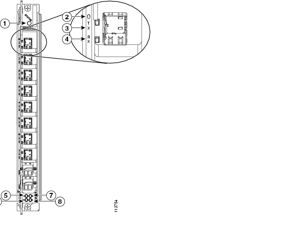
Figure 1-25 shows a splitter protected 8-port multi-service muxponder.
Figure 1-25 8-Port Multi-Service Muxponder (Splitter)
Status LED
Trunk Tx (transmit) LED
Port number
Trunk Rx (receive) LED
Port Tx (transmit)
Trunk east LED
Port Rx (receive)
Trunk west LED
Table 1-18 lists the LEDs on the 8-port multi-service muxponder faceplate, their default conditions, and what the conditions indicate.
The 8-port multi-service muxponder uses SFPs for the client signals. There are no restrictions on populating the line card with SFPs. For example, you can mix a single-mode SFP with a multimode SFP on the same card. Table 1-19 lists the characteristics for the SFPs supported by the 8-port multi-service muxponder.
Table 1-19 8-Port Multi-Service Muxponder SFP Characteristics
15500-XVRA-10A2
Low band 8 Mbps to 200 Mbps
MM 50/125 Βm MM 62.5/125 Βm
1310 nm
LC
15500-XVRA-10B2
Low band 8 Mbps to 200 Mbps
SM 9/125 Βm
1310 nm
LC
15500-XVRA-11A2
Mid-band 200 Mbps to 622 Mbps
MM 62.5/125 Βm
1310 nm
LC
15500-XVRA-11B2
Mid-band 200 Mbps to 1.25 Gbps
SM 9/125 Βm
1310 nm
LC
15500-XVRA-12B1
High-band 1.062 Gbps to 2.488 Gbps
SM 9/125 Βm
1310 nm
LC
15454-SFP-GEFC-SX
Fibre Channel (2.125 Gbps), Fibre Channel (1 Gbps), Gigabit Ethernet
MM 50/125 Βm
MM 62.5/125 Βm850 nm
LC
15500-XVRA-08D1
T11 1.544 Mbps
Copper T1
-
RJ-45
15500-XVRA-09D1
E1 2.044 Mbps
Copper E1
-
RJ-45
15500-XVRA-10E12
SDI and DVB-ASI3 Video
Copper Digital Video
-
Mini SMB Coax
15500-XVRA-11D1 4
GE 1.25 Gbps, FE 1.25 Mbps
Copper GE/FE
-
RJ-45
1 DSX-1 interface
2 In a normal operating environment, the maximum digital video application connection length using a Belden 1694A cable is 200 m (218 yd). If the chassis ambient operating temperature is above 45ΑC (113Α F) and ports 0 and 1 are used for video applications with this SFP, the maximum cable connection length supported may be less than the specified 200 m (218 yd), depending on the operating environment.
3 Data Video Broadcast Asynchronous Serial Interface
4 To ensure proper operation of the 15500-XVRA-11D1 SFP, the ambient operating temperature should not exceed 45ΑC (113ΑF).
The following warning applies to the copper SFPs listed in Table 1-19.
Warning
15500-XVRA-08D1, 15500-XVRA-09D1, 15500-XVRA-10E1 and 15500-XVRA-11D1. Statement 1044
Note
2.5-Gbps ITU Trunk Cards
The 2.5-Gbps ITU trunk card sends and receives the ITU grid wavelength signal to and from an OADM module. This card accepts a 2.5-Gbps (3.125-Gbps line rate) electrical signal from either a 10-port ESCON aggregation card or an 8-port FC/GE aggregation card, which is converted to the ITU grid wavelength, or channel. The 2.5-Gbps ITU trunk card has redundant interfaces to the backplane, connecting to the switch fabrics on the active and standby CPU switch modules. The ITU laser is tunable to one of two channel frequencies. There are 16 different 2.5-Gbps ITU trunk cards (for channels 1-2, 3-4,..., 31-32) to support the 32 channels.
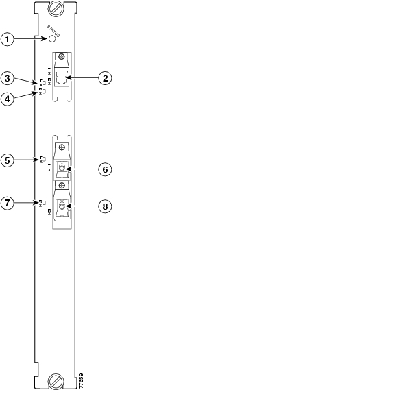
The 2.5-Gbps ITU trunk card has two versions: nonsplitter (shown in Figure 1-26) and splitter (shown in Figure 1-27). The nonsplitter version has only one pair of optical connectors on the front panel, which connects to either the east or the west OADM module, and can be used for unprotected, line card protected, or switch fabric protected applications. The card supports 32 channels as shown in Table A-2 on page A-3.
Figure 1-26 2.5-Gbps ITU Trunk Card (Nonsplitter)
Figure 1-27 2.5-Gbps ITU Trunk Card (Splitter)
Card status LED
Receive LED
West side port LED
East side port LED
West side port
East side port
Transmit LED
Table 1-20 lists and describes the 2.5-Gbps ITU Trunk Card LEDs.
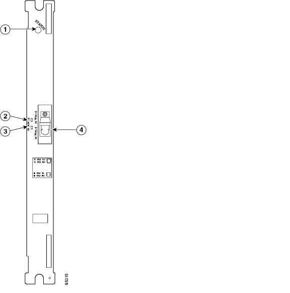
10-Gbps ITU Trunk Cards
The 10-Gbps ITU trunk card sends and receives the ITU grid wavelength signal to and from an OADM module. This card accepts up to four 2.5-Gbps (3.125-Gbps line rate) electrical signals from the 10-port ESCON aggregation cards and 8-port FC/GE aggregation cards, and combines them into one 10-Gbps signal, which is converted to the ITU grid wavelength, or channel. The 10-Gbps ITU trunk card has four separate redundant interfaces to the backplane, each connecting to the switch fabrics on the active and standby CPU switch modules.
The 10-Gbps ITU trunk card has two versions: nonsplitter and splitter. The nonsplitter version has only one pair of optical connectors on the front panel, which connects to either the east or the west OADM module, and can be used for unprotected, line card protected, or switch fabric protected applications (see Figure 1-28). The splitter version of the 10-Gbps ITU trunk card has two pairs of optical connectors on the front panel, which connect to the east and west OADM modules, and is designed for splitter protected applications (see Figure 1-29).
The Cisco ONS 15530 supports up to four 10-Gbps ITU trunk cards for a total of four channels.
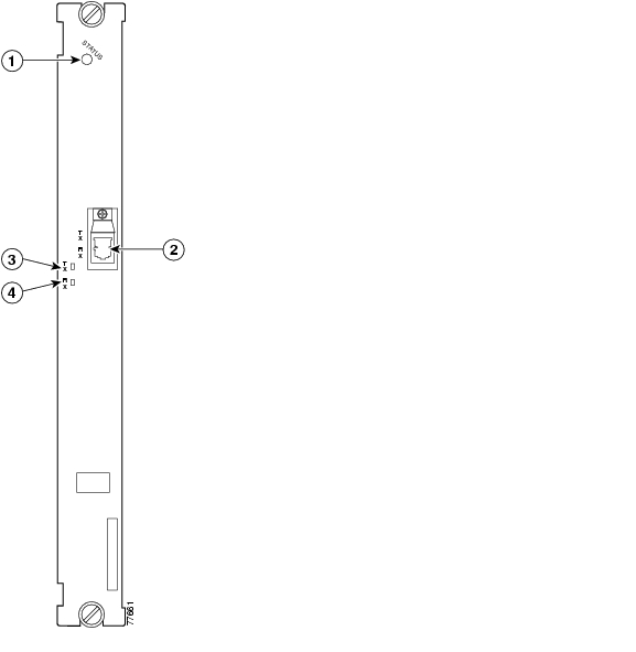
Figure 1-28 10-Gbps ITU Trunk Card (Nonsplitter)
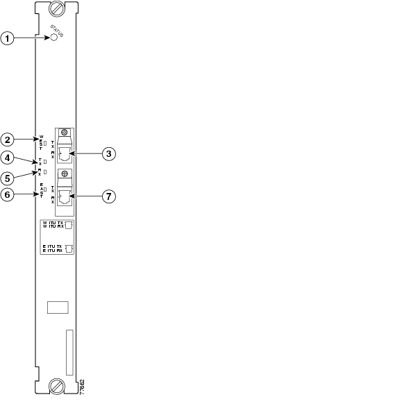
Figure 1-29 10-Gbps ITU Trunk Card (Splitter)
Card status LED
Receive LED
West side port LED
East side port LED
West side port
East side port
Transmit LED
Table 1-21 describes the10-Gbps ITU trunk card LED status.
10-Gbps ITU Tunable Trunk Cards
The 10-Gbps ITU tunable trunk card works similar to the 10-Gbps ITU trunk card. The 10-Gbps ITU tunable trunk card sends and receives the ITU grid wavelength signal to and from an OADM module. This card accepts up to four 2.5-Gbps (3.125-Gbps line rate) electrical signals from the 10-port ESCON aggregation cards and 8-port FC/GE aggregation cards, and combines them into one 10-Gbps signal, which is converted to the ITU grid wavelength, or channel. The 10-Gbps ITU tunable trunk card has four separate redundant interfaces to the backplane, each connecting to the switch fabrics on the active and standby CPU switch modules.
The 10-Gbps ITU tunable trunk card has two versions: nonsplitter and splitter. The nonsplitter version has only one pair of optical connectors on the front panel, which connects to either the east or the west OADM module, and can be used for unprotected, line card protected, or switch fabric protected applications (see Figure 1-30). The splitter version of the 10-Gbps ITU tunable trunk card has two pairs of optical connectors on the front panel, which connect to the east and west OADM modules, and is designed for splitter protected applications (see Figure 1-31).
The Cisco ONS 15530 supports up to four 10-Gbps ITU tunable trunk cards for a total of four channels. The 10-Gbps ITU tunable trunk cards are equipped with Universal Transponders (UT1) with tuneable lasers. The cards are programmable to four different frequencies belonging to one of the A, B, C, D, E, F, G, or H bands. For more information on tunable frequencies, see Cisco ONS 15530 Planning Guide.
Figure 1-30 10-Gbps ITU Tunable Trunk Card (Nonsplitter)
Figure 1-31 10-Gbps ITU Tunable Trunk Card (Splitter)
Card status LED
Receive LED
West side port LED
East side port LED
West side port
East side port
Transmit LED
Table 1-22 describes the10-Gbps ITU tunable trunk card LED status.
10-Gbps Uplink Cards
The 10-Gbps uplink card, shown in Figure 1-32, sends and receives a 10-GE 1310-nm signal to and from a 10-GE uplink card on another Cisco ONS 15530, or to and from a 10-GE transponder module on a Cisco ONS 15540 ESP or Cisco ONS 15540 ESPx. This card accepts up to four (3.125-Gbps line rate) electrical signals from 10-port ESCON aggregation cards and 8-port FC/GE aggregation cards, and combines them into one 10-GE signal.
The 10-Gbps uplink card has four separate redundant interfaces to the backplane. Each interface connects to the switch fabric on the active and standby CPU switch modules.
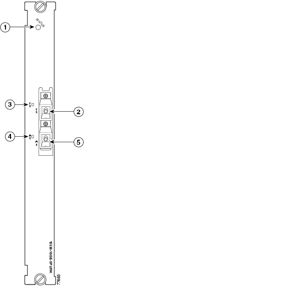
The 10-Gbps uplink card has only one version: nonsplitter. The nonsplitter version has only one pair of optical connectors on the front panel and can be used for unprotected or line card protected applications. For splitter protected configurations, the splitter line card motherboards on the Cisco ONS 15540 ESP and the Cisco ONS 15540 ESPx provide the facility protection.
The Cisco ONS 15530 supports up to four 10-Gbps uplink cards for a total of four signals.
Figure 1-32 10-Gbps Uplink Card
Table 1-23 describes the 10-Gbps uplink line card LED status.
![]()
![]()
![]()
![]()
![]()
![]()
![]()
![]()
Posted: Wed May 31 10:22:33 PDT 2006
All contents are Copyright © 1992--2006 Cisco Systems, Inc. All rights reserved.
Important Notices and Privacy Statement.