|
|

This chapter describes the features and hardware components of the Catalyst 5000 family switches and includes the following sections:
 |
Note The information in this chapter applies to all Catalyst 5000 family switches unless otherwise noted. |
This section describes the Catalyst 5000 family hardware features. For software feature descriptions, refer to the Software Configuration Guide for your switch. For supervisor engine descriptions and installation procedures, refer to the Catalyst 5000 Family Supervisor Engine Installation Guide.
The Catalyst 5000 family switches have the following features:
All modules (including the supervisor engine if you have redundant supervisors), fans, and dual power supplies, support hot-swapping, so that you can add, replace, or remove modules without interrupting the system power or causing other software or interfaces to shut down. For information about hot-swapping supervisor engines, refer to the Catalyst 5000 Family Supervisor Engine Installation Guide.
This section describes the Catalyst 5000 family hardware components.
The standard and optional equipment available for individual switches is listed in this section.
The Catalyst 5002 switch has the following standard equipment:
The Catalyst 5002 switch has optional switching modules.
These switches have the following standard equipment:
These switches have the following optional equipment:
The system fan assembly provides cooling air for the supervisor engine, the switching modules, and the backplane. The fan assembly is located in the chassis.
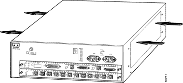
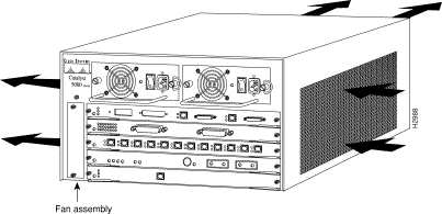
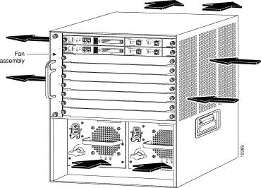
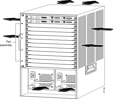
The following figures show the direction of airflow in to and out of the switches:
If an individual fan within an assembly fails, the fan LED on the supervisor engine turns red. Sensors on the supervisor engine also monitor the internal air temperatures. If the air temperature exceeds a desired threshold, the environmental monitor displays warning messages. For specific threshold and status level descriptions, see the "Power Supplies" section.
To replace a fan assembly, see "Removal and Replacement Procedures."
For complete environmental specifications, including airflow requirements, see "Specifications."
 |
Note The Catalyst 5002 fan assembly is not a field-replaceable unit (FRU). |
 |
Note The airflow shown in Figure 2-1 is the same for the Catalyst 5002 equipped with DC-input power supplies. |
 |
Note For complete power specifications, see "Specifications." |
The Catalyst 5000 family power supplies differ for each switch.
 |
Note Catalyst 5002 power supplies are described later in this section. |
 |
Note Important Power Supply Information—The Catalyst 5505 switch requires power supply WS-C5008B. The Catalyst 5505 switch might have short-term power peaks, which this new supply is designed to handle. The Catalyst 5000 switch can use either WS-C5008A or WS-C5008B. These units are fully compatible in the Catalyst 5000 chassis. |
The Catalyst 5000, Catalyst 5505, Catalyst 5509, and Catalyst 5500 switches support redundant AC-input or DC-input power supplies. When using dual power supplies, both must be the same type, that is, either AC- or DC-input power. Each power supply has an individual power switch and a status LED on the supervisor engine.
Many telco organizations require a -48 VDC power supply to accommodate their power distribution systems. From an operational perspective, the DC power supply has the same characteristics as the AC version.
The AC-input power supply has a power cord that connects each power supply to the site power source. The DC-input power supplies are connected to the power source with heavy gauge wiring connected to a terminal block. The AC-input power supplies are shown in Figure 2-5. The DC-input power supplies are shown in Figure 2-6 (Catalyst 5000, Catalyst 5505, and Catalyst 5509 switches) and Figure 2-7 (Catalyst 5500 switch).
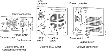
Both AC-input and DC-input power supplies support redundant hot swapping. When power is removed from one power supply, the redundant power feature causes the second power supply to produce full power.
 |
Note You cannot power the Catalyst 5000, Catalyst 5505, Catalyst 5509, and Catalyst 5500 switches with AC-input and DC-input power supplies in the same chassis. |
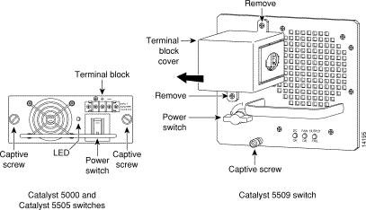
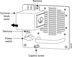
When two power supplies are installed and turned on, each concurrently provides approximately half of the required power to the system. If one power supply fails, the second power supply immediately assumes full power to maintain uninterrupted system operation. Load sharing and fault tolerance are enabled automatically when you install the second power supply; no software configuration is required.
 |
Note Catalyst 5509 and Catalyst 5500 switches only—For proper load sharing operation in a redundant power supply configuration, you must install at least two modules in the chassis. Failure to install at least two modules may result in spurious Output Fail indications on one or both power supplies. |
Using the environmental monitoring and reporting functions, you can maintain normal system operation by resolving adverse environmental conditions prior to loss of operation.
Each power supply monitors its own temperature and output voltages. If conditions reach critical thresholds, the system might shut down to avoid damaging equipment from excessive heat or electrical current.
The supervisor engine power supply status LEDs (PS1 and PS2) are described in Chapter 1, "Product Overview," in the Catalyst 5000 Family Supervisor Engine Installation Guide.
The power supply front panel LEDs are described in Table 2-1.
| LED | State | Description |
|---|---|---|
| Catalyst 5500 and 5509 AC- and DC-input power supplies: | ||
AC OK |
| Indicates the status of the input voltage. |
| Green | Input voltage is okay. |
| Red | There is a problem with the input voltage. |
| Indicates whether or not the fan is operational. | |
| Green | The fan is operational. |
| Red | The fan is not operational. |
OUTPUT FAIL |
| Indicates the status of the DC power output voltage of the power supplies. |
| Off | The DC power output voltage of the power supplies are operational. |
| Red | There is a problem with the DC output voltage of one or more power supplies. |
| Catalyst 5000 and 5505 AC- and DC-input power supplies: | ||
POWER SUPPLY |
| Indicates the status of the power supply. |
| Green | The power supply is operational. |
| Red | There is a problem with the power supply. |
 |
Note Some versions of the power AC-input power supply may not be able to detect output undervoltage conditions when operating in a redundant configuration. |
The power supplies monitor their own internal temperature and voltages. Table 2-2 and Table 2-3 list temperature thresholds for the processor-monitored levels.
| Parameter | Normal | Alarm |
|---|---|---|
Temperature | < 45ºC | > 45ºC |
| Parameter | Normal | Alarm |
|---|---|---|
Temperature | 10-55ºC | > 55ºC |
Table 2-4 shows whether the power system is either within tolerance (normal) or out of tolerance (critical level).
| Parameter | Critical | Normal | Critical |
|---|---|---|---|
+5V | < 4.74V | 4.74 to 5.26V | > 5.26V |
+12V | < 11.4V | 11.40 to 12.6V | > 12.6V |
+24V | < 20V | 20.00 to 30V | > 30V |
The power supplies have a built-in fan; air enters the front of the fan (power-input end) and exits through the back. An air dam keeps the airflow separate from the rest of the chassis, which is cooled by the system fan assembly.
To replace a power supply, see "Removal and Replacement Procedures."
The Catalyst 5002 switch is configured with either two internal AC-input power supplies or two internal DC-input power supplies. Each power supply has a status LED on the supervisor engine.
The dual power supplies operate in a load-sharing mode. If one power supply fails, the other supply fully powers the system without interruption.
In normal operation, each power supply concurrently provides approximately half of the required power to the system. If one power supply fails, the second power supply immediately assumes full power to maintain uninterrupted system operation. Load sharing and fault tolerance are enabled automatically.
The supervisor engine front panel has two LEDs that provide power indications. The LEDs (PS1 and PS2) are described in Chapter 1, "Product Overview," in the Catalyst 5000 Family Supervisor Engine Installation Guide.
Catalyst 5002 switches that are equipped with the 175W power supply have the power factor correction (PFC) feature. PFC reduces harmonic distortion and increases transmission efficiency. For more information on the Catalyst 5002 switch and the 175W power supply with PFC, see the "Catalyst 5002 Switch" section.
![]()
![]()
![]()
![]()
![]()
![]()
![]()
![]()
Posted: Tue Sep 26 10:33:56 PDT 2000
Copyright 1989-2000©Cisco Systems Inc.