|
|

This chapter describes the Catalyst 5000 family switches. For detailed descriptions of system features and components, see "Switch Description."
 |
Note For a detailed description of supervisor engine operation in a redundant configuration, see Chapter 3, "Installing the Supervisor Engine," in the Catalyst 5000 Family Supervisor Engine Installation Guide. |
The Catalyst 5000 family consists of five modular LAN switches:
|
Note Throughout this guide and all Catalyst 5000 family documents, "Catalyst 5000 family switches" refers to all of the Catalyst 5000 switches unless otherwise noted. |
All switches share the same set of modules and software features—providing scalability while maintaining interoperability across all platforms.
All switches accept Ethernet, Fast Ethernet, Gigabit Ethernet, Fiber Distributed Data Interface (FDDI), Copper Distributed Data Interface (CDDI), and ATM modules. All switches, except the Catalyst 5002 switch, accept the Route Switch Module (RSM) and the RSM/Versatile Interface Processor 2 (VIP2). The Catalyst 5500 switch accepts LightStream 1010 ATM modules.
The Catalyst 5505, Catalyst 5509, and Catalyst 5500 switches accept redundant supervisor engines.
All switches can use Category 5 unshielded twisted-pair (UTP) cabling, coaxial cable, and multimode and single-mode fiber-optic cable.
Typically, Catalyst 5000 family Ethernet interfaces connect workstations and repeaters while the Fast Ethernet interfaces connect workstations, servers, switches, and routers. The nine-port Gigabit Ethernet switching module provides a high-performance gigabit switching backbone while the Supervisor Engine III Gigabit Ethernet interfaces serve as uplinks that aggregate traffic from high-density 10/100-Mbps wiring closets. The Gigabit EtherChannel switching module is used primarily for backbone interconnection of other high-performance Catalyst 5000 family switches and Cisco routers through Gigabit EtherChannel.
Table 1-1 lists and describes the Catalyst 5000 family switches.
| Switch | Description | Features | ||
|---|---|---|---|---|
2-slot switch |
| |||
Catalyst 5002 (continued) |
|
| ||
5-slot switch |
| |||
5-slot switch |
| |||
Catalyst 5505 (continued) |
|
| ||
9-slot switch |
| |||
13-slot switch |
| |||
Catalyst 5500 (continued) |
|
|
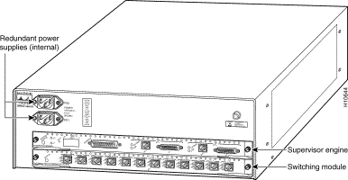
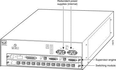
The Catalyst 5002 switch chassis has two slots. Slot 1 is for the supervisor engine, which provides switching, local and remote management, and multiple uplink interfaces. Slot 2 is available for switching modules.
The Catalyst 5002 switch comes equipped either with a 155W power supply or a 175W power supply with PFC. Figure 1-1 shows the Catalyst 5002 switch with a 155W power supply. Figure 1-2 shows the Catalyst 5002 switch with a 175W power supply with PFC.
|
Note The Catalyst 5002 switch with 155W power supply does not support Supervisor Engine III. |
The Catalyst 5002 switch has a 1.2-Gbps media-independent switching fabric that provides the connections between power supplies, the supervisor engine, and the switching module. This switching fabric supports wire-speed switching for the supported line modules. See Table 1-1 for additional information.
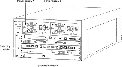
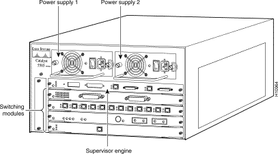
The Catalyst 5000 switch chassis has five slots. (See Figure 1-3.) Slot 1 is for the supervisor engine, which provides switching, local and remote management, and dual uplink interfaces. Slots 2 through 5 are available for switching modules.
The Catalyst 5000 switch has a 1.2-Gbps media-independent switching fabric that provides the connections between power supplies, the supervisor engine, and the switching modules. This switching fabric supports wire-speed switching for the supported line modules. See Table 1-1 for additional information.
The Catalyst 5505 switch chassis has five slots. (See Figure 1-4.) Slot 1 is for the supervisor engine, which provides switching, local and remote management, and dual uplink interfaces. Slot 2 can contain an additional redundant supervisor engine, which acts as a backup function in case the first module fails. A failure of the active supervisor engine is detected by the standby module, which then takes control of the supervisor engine switching functions. If a redundant supervisor engine is not required, slots 2 through 5 are available for switching modules.
The Catalyst 5505 switch is an enhanced version of the Catalyst 5000 switch with a three-bus, 3.6-Gbps media-independent switching fabric that provides the connections between power supplies, the supervisor engine, and the switching modules. The 3.6-Gbps media-independent fabric supports Ethernet, Fast Ethernet, Gigabit Ethernet, FDDI/CDDI, ATM LAN Emulation (LANE), ATM dual physical layer (PHY) DS3, RSM, and RSM/VIP2 modules. See Table 1-1 for additional information.
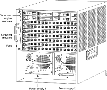
The Catalyst 5509 switch chassis has nine slots. (See Figure 1-5.) Slot 1 is for the supervisor engine, which provides switching, local and remote management, and multiple uplink interfaces. Slot 2 can contain an additional redundant supervisor engine, which acts as a backup in case the first module fails. A failure of the active supervisor engine is detected by the standby module, which then takes control of the supervisor engine switching functions. If a redundant supervisor engine is not required, slots 2 through 9 are available for switching modules.
The Catalyst 5509 switch has a three-bus, 3.6-Gbps media-independent switching fabric that provides the connections between power supplies, the supervisor engine, and the switching modules. The three-bus, 3.6-Gbps backplane is accessible from all nine slots. The 3.6-Gbps media-independent fabric supports Ethernet, Fast Ethernet, Gigabit Ethernet, FDDI/CDDI, ATM LANE, ATM dual PHY DS3, RSM, and RSM/VIP2 modules. See Table 1-1 for additional information.
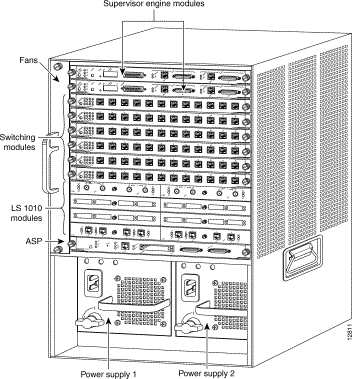
The Catalyst 5500 switch chassis has 13 slots. (See Figure 1-6.) Slot 1 is for the supervisor engine, which provides switching, local and remote management, and multiple uplink interfaces. Slot 2 can contain an additional redundant supervisor engine, which acts as a backup in case the first module fails. A failure of the active supervisor engine is detected by the standby module, which takes control of supervisor engine switching functions. If a redundant supervisor engine is not required, slot 2 is available for any switching module.
Slots 3 through 12 are available for any combination of switching modules.
Slot 13 is a dedicated slot, which accepts only the ATM switch processor (ASP) module or the Catalyst 8510 Campus Switch Router (CSR) switch route processor (SRP). When using the ASP in slot 13, the Catalyst 5500 switch accepts LightStream 1010 ATM port adapters in slots 9 through 12. When using the Catalyst 8510 CSR SRP in slot 13, the Catalyst 5500 switch accepts Catalyst 8510 CSR modules in slots 9 through 12.
The Catalyst 5500 switch has a 3.6-Gbps media-independent switch fabric and a 5-Gbps cell-switch fabric. The backplane provides the connection between power supplies, supervisor engine, switching modules, and backbone module. The 3.6-Gbps media-independent fabric supports Ethernet, Fast Ethernet, Gigabit Ethernet, FDDI/CDDI, ATM LANE, ATM dual PHY DS3, RSM, and RSM/VIP2 modules. The 5-Gbps cell-based fabric supports an ASP module and ATM port adapters. See Table 1-1 for additional information.
![]()
![]()
![]()
![]()
![]()
![]()
![]()
![]()
Posted: Tue Sep 26 10:33:32 PDT 2000
Copyright 1989-2000©Cisco Systems Inc.