|
|

 |
Warning Before you install, operate, or service the system, read the Site Preparation and Safety Guide. This guide contains important safety information you should know before working with the system. |
 |
Note The information in this chapter applies to all Catalyst 5000 family switches unless otherwise noted. |
This chapter describes how to perform the following removal and replacement procedures for Catalyst 5000 family field-replaceable units (FRUs):
For instructions on installing and replacing switching modules, refer to the Catalyst 5000 Family Module Installation Guide.
For instructions on installing and replacing supervisor engines, supervisor engine uplink modules and Flash PC cards, refer to the Catalyst 5000 Family Supervisor Engine Installation Guide.
For instructions on upgrading a Supervisor Engine III with the NetFlow Feature Card (NFFC), refer to the Catalyst 5000 Family Multilayer Switching User Guide.
 |
Note The Catalyst 5002 power supplies are not FRUs. Instructions for connecting the input wires to the DC-input power supplies are included in the "Connecting DC-Input Wires on the Catalyst 5002 Switch" section. |
This section describes how to remove and install power supplies for the Catalyst 5000, Catalyst 5505, Catalyst 5509, and Catalyst 5500 switches. A flat-blade screwdriver is required to perform these procedures.
This warning applies to Catalyst 5500 AC-input power supplies only.
 |
Warning A design problem might affect a small percentage of Catalyst 5500 AC-input power supplies shipped as spares and AC-input power supplies shipped with chassis orders between December 1996 and December 1997. If you do not handle these power supplies with caution, you might experience a mild shock. We do not believe that the risk associated with this design problem is significant. We believe that the current design is safe when the power supply is handled correctly. To safely remove AC-input power from the Catalyst 5500 power supply, use the procedure in the next section. The power supply manufacturer, with technical assistance from Cisco, has implemented a design change to correct the problem. In addition, we will provide replacement AC-input power supplies to any customer upon request at no cost to the customer. To arrange for a replacement, contact Cisco Systems Customer Service at 800 553-NETS (6387), 408 526-7208, or e-mail cs-rep@cisco.com. If you need further technical assistance, contact the Technical Assistance Center (TAC) at 800 553-24HR (2447) or e-mail tac@cisco.com. |
Remove power from the AC-input power supply as follows:
Step 2 Turn off the power switch on the power supply you are removing.
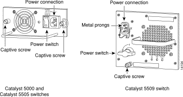
Step 3 Remove the power cord from the power connection on the supply. Do not touch the metal prongs embedded in the power supply.
Step 4 Continue the power supply removal with Step 4 in the following procedure.
 |
Note The Catalyst 5505 switch requires power supply WS-C5008B. The Catalyst 5505 switch might have short-term power peaks that this new supply is designed to handle. The Catalyst 5000 switch can use either WS-C5008A or WS-C5008B. These units are fully compatible in the Catalyst 5000 chassis. |
 |
Caution Do not mix AC-input and DC-input power supplies in the same switch. |
 |
Note In systems with redundant power supplies, you can replace the faulty supply while the system is operating. |
To remove an AC-input power supply, follow these steps:
 |
Caution Failure to turn off the power supply could result in equipment damage. |
Step 2 Disconnect the power cord from the power source.
Step 3 Disconnect the power cord from the power supply being removed.
Step 4 Use a flat-blade screwdriver to loosen and remove the captive installation screws. (See Figure 5-1 for the Catalyst 5000, Catalyst 5505, and Catalyst 5509 switches, and Figure 5-2 for the Catalyst 5500 switch.)
 |
Caution Catalyst 5000 and Catalyst 5505 switches—Make sure you turn the captive installation screws simultaneously. If you fail to do this, the power supply might stick in the chassis and damage the captive installation screws. |
 |
Caution Use both hands to install and remove power supplies. |
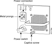
Step 5 Grasp the power supply handle with one hand. Place your other hand underneath to support the bottom of the supply, as shown in Figure 5-3 (Catalyst 5000 power supply is shown).

Step 6 Pull the supply out of the bay and put it aside.
Step 7 If the power supply bay is to remain empty, install a blank power supply filler plate over the opening; secure it with the mounting screws.
 |
Note The Catalyst 5505 switch requires power supply WS-C5008B. The Catalyst 5505 switch might have short-term power peaks that this new supply is designed to handle. The Catalyst 5000 switch can use either WS-C5008A or WS-C5008B. These units are fully compatible in the Catalyst 5000 chassis. |
Follow these steps to install an AC-input power supply, connect it to a power source, and verify its operation:
 |
Caution Failure to turn off the power supply could result in equipment damage. |
 |
Caution Use both hands to install and remove power supplies. The weight for each power supply is as follows: |
Step 2 Grasp the power supply handle with one hand. Place your other hand underneath to support the bottom of the supply, as shown in Figure 5-3.
Step 3 Slide the power supply all the way into the power supply bay.
Step 4 Use a flat-blade screwdriver to tighten the captive installation screws. (See Figure 5-1 for the Catalyst 5000, Catalyst 5505, and Catalyst 5509 switches, and Figure 5-2 for the Catalyst 5500 switch.)
 |
Caution Catalyst 5000 and Catalyst 5505 switches—Make sure you turn the captive installation screws simultaneously. If you fail to do this, the power supply might stick in the chassis and damage the captive installation screws. |
Step 5 Prior to connecting the power supply to a power source, ensure that all site power and grounding requirements described in "Site Planning," have been met.
Step 6 Plug the power cord into the power supply.
Step 7 Connect the other end of the power cord to an AC-input power source.
 |
Note Catalyst 5500 switch only—Each AC-input power supply operating at 120 VAC requires a dedicated 20A service and 20A plug and receptacle. It is not acceptable to power the Catalyst 5500 switch from a 15A line cord because of the safety ratings under which the Catalyst 5500 switch has been certified. |
 |
Caution In a system with dual power supplies, connect each power supply to a separate input source. In case of a power source failure, the second source will most likely still be available and can maintain maximum overcurrent protection for each power connection. |
Step 8 Turn the power switch to the On (|) position on the power supply.
Step 9 Verify power supply operation.
Catalyst 5000 and Catalyst 5505 switches—Verify that the green LED on the power supply front panel is lit. This indicates that the power supply is on and receiving AC source power, providing +5, +12, and +24 VDC to internal components, and all internal voltages are within tolerance.
Catalyst 5509 and Catalyst 5500 switches—Verify that the power supply front panel LEDs are in the following states:
Catalyst 5000, Catalyst 5505, Catalyst 5509, and Catalyst 5500 switches— Verify that the appropriate supervisor engine module PS1 and PS2 LEDs are green.
Enter the show system command to display the power supply and system status.
If the LEDs or show system command indicate a power or other system problem, see "Troubleshooting the Installation," for troubleshooting information.
Follow these steps to remove a DC-input power supply:
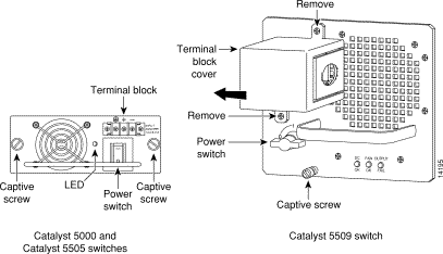
Step 2 Turn the power switch to the Off (0) position on the power supply you are removing. (See Figure 5-4 for the Catalyst 5000, Catalyst 5505, and Catalyst 5509 switches, and Figure 5-5 for the Catalyst 5500 switch.)
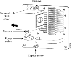
Step 3 Remove the terminal block cover (see Figure 5-4 for the Catalyst 5000, Catalyst 5505, and Catalyst 5509 switches, and Figure 5-5 for the Catalyst 5500 switch).
Catalyst 5000 and Catalyst 5505 switches—Press down the two plastic levers on each side of the terminal block cover and then remove the cover.
Catalyst 5509 and Catalyst 5500 switches—Remove the two screws securing the terminal block cover and slide the cover straight off the terminal block.
Step 4 Disconnect the DC-input wires from the terminal block. Disconnect the ground wire last.
Step 5 Use a screwdriver to loosen and remove the captive screws on the power supply. (See Figure 5-4 for the Catalyst 5000, Catalyst 5505, and Catalyst 5509 switches, and Figure 5-5 for the Catalyst 5500 switch.)
 |
Caution Catalyst 5000 and Catalyst 5505 switches—Make sure you turn the captive installation screws simultaneously. If you fail to do this, the power supply might stick in the chassis and damage the captive installation screws. |
 |
Caution Use both hands to remove and install power supplies. |
Step 6 Grasp the power supply handle with one hand. Place your other hand underneath as you slowly pull the power supply out of the bay. (See Figure 5-6.)

Step 7 If the bay is to remain empty, install a blank power supply filler plate (Cisco part number 700-00177-01) over the opening and secure it with the mounting screws. This protects the inner chassis from dust and prevents accidental contact with live voltage at the rear of the bay.
 |
Caution Always install a filler plate over an empty power supply bay, not only to protect the inner chassis and connectors from dust or other contamination, but to prevent possible contact with the high current levels of those connectors when the chassis is turned on. |
Step 8 Reinstall the power supply terminal block cover.
To install a DC-input power supply, connect it to a power source, verify its operation, and follow these steps:
Step 2 Connect the switch to the central office (CO) ground through the CO ground connector shown in Figure 5-7. Remove the adhesive strip covering the CO ground connector on the switch.
Use the following guidelines when connecting the switch to the CO ground:
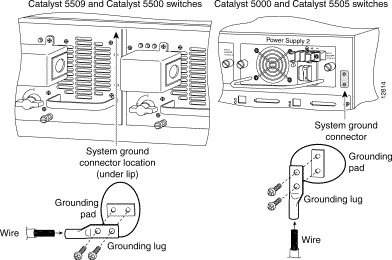
Step 3 Turn the power switch to the Off (0) position on the power supply you are installing. (See Figure 5-4 for the Catalyst 5000, Catalyst 5505, and Catalyst 5509 switches, and Figure 5-5 for the Catalyst 5500 switch.)
 |
Caution Use both hands to remove and install power supplies. |
Step 4 Grasp the power supply handle with one hand. Place your other hand underneath as you slowly insert the power supply into the bay. (See Figure 5-6.)
Step 5 Use a screwdriver to tighten the captive screws on the power supply. (See Figure 5-4 for the Catalyst 5000, Catalyst 5505, and Catalyst 5509 switches, and Figure 5-5 for the Catalyst 5500 switch.)
 |
Caution Catalyst 5000 and Catalyst 5505 switches—Make sure you turn the captive installation screws simultaneously. If you fail to do this, the power supply might stick in the chassis and damage the captive installation screws. |
Step 6 Remove the terminal block cover (see Figure 5-4 for the Catalyst 5000, Catalyst 5505, and Catalyst 5509 switches, and Figure 5-5 for the Catalyst 5500 switch).
Catalyst 5000 and Catalyst 5505 switches—Press down the two plastic levers on each side of the terminal block cover and remove the cover.
Catalyst 5509 and Catalyst 5500 switches—Remove the two screws securing the terminal block cover and slide the cover straight off the terminal block.
Step 7 Attach the appropriate lugs to the DC-input wires.
Maximum width of the lugs is 0.300 inch (7.6 mm). Suggested lugs are AMP 322985 or 52941. Suggested DC-input wires (90-degree copper conductors) are as follows:
 |
Note Catalyst 5500 switch only—We recommend that you use UL-listed crimp lugs and the appropriate crimp tool for installation. We recommend either the Thomas and Betts, No. 54104 or BURNDY No.YA8CLBOX crimp lug and either the Thomas and Betts Model TBM12 or TBM15 Hydraulic Head crimping tool. Crimp the lugs to the specifications given in the manufacturer's instructions furnished with the lug or crimp tool. |
 |
Caution When stranded wiring is required, use approved wiring terminations, such as closed-loop or spade-type with upturned lugs. These terminations should be the appropriate size for the wires and should clamp both the insulation and conductor. |
Step 8 Connect the DC-input wires to the terminal block.
Catalyst 5000 and Catalyst 5505 switches—From the top of the terminal block, connect the DC-input wires to the terminal block as follows (see Figure 5-8):
 |
Note Be sure to route the wires from the top of the terminal block to allow access to the power supply switch. |
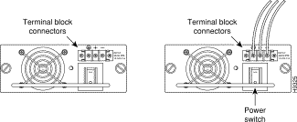
Catalyst 5509 and Catalyst 5500 switches—Route the DC-input power cable through the conduit from your power source, through the conduit bracket on the power supply. Make a sufficient length of wire available to attach to the three terminal block connections.
Attach and tighten the conduit to the conduit bracket. The method to attach this conduit depends on your site; the attachment procedure is beyond the scope of this publication.
Connect the DC-input wires to the terminal block. See Figure 5-9 (Catalyst 5509 switch) or Figure 5-10 (Catalyst 5500 switch). The proper wiring sequence is ground to ground, positive to positive (line to L), and negative to negative (neutral to N). You should always connect the ground wire first and disconnect the ground wire last.
 |
Caution Connect the ground wire first. |
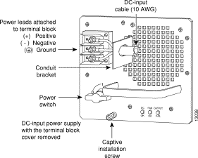
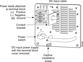
Step 9 After ensuring that all wire connections are secure, reinstall the terminal block cover.
 |
Caution To prevent a short-circuit or shock hazard after wiring the DC-input power supply, reinstall the terminal block cover. |
 |
Caution Figure 5-9 (Catalyst 5509 switch) and Figure 5-10 (Catalyst 5500 switch) show the DC power supply terminal block. Wire the DC power supply using the appropriate lugs at the wiring end, as illustrated. The proper wiring sequence is ground to ground, positive to positive (line to L), and negative to negative (neutral to N). You should always connect the ground wire first and disconnect the ground wire last. |
 |
Caution Connect the ground wire first. |
 |
Caution In a system with dual power supplies, use the modular power cord to connect each power supply to a separate input line. In case of a line failure, the second source will most likely still be available and can maintain maximum overcurrent protection for each power connection. |
Step 10 Remove the tape from the circuit breaker switch handle and restore power by moving the circuit breaker switch handle to the On (|) position.
Step 11 Turn the power switch to the On (|) position on the power supply.
Step 12 Verify power supply operation.
Catalyst 5000 and Catalyst 5505 switches—Verify that the green LED on the power supply front panel is on. This indicates that the power supply is on and receiving DC source power, providing +5, +12, and +24 VDC to internal components, and all internal voltages are within tolerance.
Catalyst 5509 and Catalyst 5500 switches—Verify that the power supply front panel LEDs are in the following states:
Catalyst 5000, Catalyst 5505, Catalyst 5509, and Catalyst 5500 switches—Verify that the appropriate supervisor engine PS1 and PS2 LEDs are green.
Enter the show system command to display the power supply and system status.
If the LEDs or show system command indicate a power or other system problem, see "Troubleshooting the Installation."
To connect the DC-input wires to the DC-input power supplies, follow the steps in this section.
The required tools and materials are as follows:
To connect the DC-input wires, follow these steps:
Step 2 Remove the adhesive strip covering the CO ground point on the switch, and then connect the switch to the CO ground through the CO ground point (located at the lower left side of the switch).
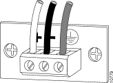
Step 3 Connect the DC-input wires to the terminal block as follows (see Figure 5-11):
a. Using a small flathead screwdriver, loosen the three screws on the terminal block.
b. From the top of the terminal block, insert the input wires as follows:
c. Tighten the three screws, ensuring that each input wire is securely connected.
d. Repeat Step a through Step c for the other terminal block.
 |
Note Japan only: See the "Japan OnlyTerminal Block Cover Installation" section and install the terminal block cover. |
Step 4 Remove the tape from the circuit breaker switch handle; restore power by moving the circuit breaker switch handle to the On (|) position.
Step 5 Verify power supply operation as follows:
a. Listen for the system fans and ensure that the fan LED on the supervisor engine is green.
b. While the system initializes, check that the System Status LED on the supervisor engine is orange until the boot is complete.
Some interface LEDs might light or blink for a short time. Some LEDs, such as the Link LED, stay on during the entire boot process. If you already configured an interface, the LEDs might be on steadily as they detect traffic on the line. Wait until the system boot is complete before attempting to verify the switching module LED indications.
 |
Note Many switching module LEDs are not lit until you configure the interfaces. |
c. When the system boot is complete (it takes a few seconds), the supervisor engine begins to initialize the switching module.
d. Enter the show system command to display the power supply and system status.
e. Check the LEDs or the show system command display for an indication of a power or other system problem. If a problem is observed, see "Troubleshooting the Installation."
Install the terminal block cover as follows (see Figure 5-12):
 |
Note The terminal block cover and two standoffs shipped with your Catalyst 5002 switch in the DC-input power supply accessory kit. |
Step 2 Screw the two standoff posts into the two outer screw holes. Do not overtighten the standoff posts.
Step 3 Position the terminal block cover over the terminal block while carefully routing the input wires out the side of the cover.
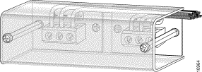
Step 4 Secure the terminal block cover using the two screws removed earlier.
Step 5 Return to Step 4 of the installation procedure.
 |
Note The Catalyst 5002 fan assemblies are not FRUs. |
This section describes how to remove and install chassis fan assemblies for the Catalyst 5505, Catalyst 5000, Catalyst 5509, and Catalyst 5500 switches. A flat-blade screwdriver is required to perform this procedure.
 |
Caution Never operate the system if the fan assembly is removed or if it is not functioning properly. An overtemperature condition can result in severe equipment damage. |
 |
Note The fan assembly is designed to be removed and replaced while the system is operating without presenting an electrical hazard or damage to the system. |
To remove the existing chassis fan assembly, follow these steps:
Step 2 Loosen the two captive installation screws by turning them counterclockwise.
Step 3 Grasp the fan assembly with both hands and pull it outward; joggle it if necessary to unseat it from the backplane. Pull it clear of the chassis and place it in a safe place.
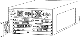
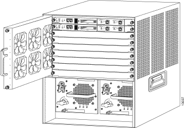
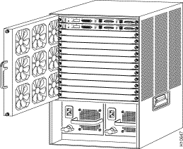
To install the new fan assembly, follow these steps:
Step 2 Place the fan assembly into the front chassis cavity so it rests on the chassis, and then lift the fan assembly up slightly aligning the top and bottom guides.
Step 3 Push the fan assembly into the chassis until the captive installation screws meet the chassis.
Step 4 Tighten the captive installation screws by turning them clockwise.
To verify that the new fan assembly is installed correctly, follow these steps:
Step 2 If after several attempts the fans do not operate, or if you experience trouble with the installation (for instance, if the captive installation screws do not align with the chassis holes), contact a Cisco customer service representative for assistance.
![]()
![]()
![]()
![]()
![]()
![]()
![]()
![]()
Posted: Tue Sep 26 10:33:59 PDT 2000
Copyright 1989-2000©Cisco Systems Inc.