|
|

This chapter gives step-by-step instructions for installing and configuring the Catalyst 3000 and verifying that it is operating properly.
This chapter covers the following topics:
Figure 5-1, "Front Panel View" and Figure 5-2, "Rear Panel View" shows the Catalyst 3000.


The Catalyst 3000 and the Catalyst Matrix mount in a standard 19-inch rack or cabinet. The installation area should be near a power source and should have enough room around the front and rear panels for cabling and access to controls. Use the following procedures for the installation of Catalyst Stack equipment.
If you install the Catalyst 3000 in a closed or multi-unit rack, observe the environmental guidelines from the last chapter, Chapter 4, "Preparing for Installation."
 | Caution The following rack mounting instructions need to be observed to ensure that the Catalyst Stack units and any other equipment are mechanically stable. |
The following steps describe how to mount the Catalyst 3000 or Catalyst Matrix in a rack or cabinet:
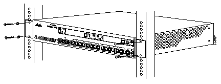
Step 1 Using a Phillips, or cross-head, screwdriver, attach the two L-shaped mounting brackets to both sides of the Catalyst 3000 or the Catalyst Matrix with four 8-mm M4 screws for each side. The following illustration, Figure 5-3, shows mounting the brackets to a Catalyst 3000 unit. The position of the brackets are the same on the Catalyst Matrix.

Before starting the next step, be sure you have the proper hardware for mounting the chassis with the attached brackets to you cabinet or rack.
Step 2 Position the Catalyst 3000 or the Catalyst Matrix in the rack or cabinet and slide it up or down until the rack holes line up with the bracket holes. Attach the Catalyst 3000 to the rack with appropriate mounting screws. Make sure you have the proper screws that fit your cabinet or rack before attempting to mount the switch.
 | Caution Due to weight constraints, place no more than one unit (or the equivalent weight of other equipment) directly on top of another chassis. More than one unit on top of another unit may cause damage to the lower unit. |
The Catalyst 3000 should be mounted in an appropriate mounting rack, but if the situation warrants, such as a shortage of rack space or location constraints, the Catalyst 3000 can be surface mounted. The unit operates at a low noise level, which makes it suitable for a work area or almost anywhere with a large enough flat surface such as a table, desktop or similar area. Simply place the unit on a clear and level location. Leave enough room around the unit for ventilation and access to the controls and cable connectors.
There are two Catalyst Stack configurations.
How to cable the Catalyst Stack equipment is described in the next two sections. The first section explains connecting two Catalyst 3000 units back-to-back. The next section describes how to connect Catalyst 3000 units to the Catalyst Matrix.
To connect two Catalyst 3000 units together, an installed Catalyst Stack Port module must be in the expansion slot in the back of each Catalyst 3000. (See Figure 5-5.) One stack port cable is used to connect to the I/O stack port on each of the Catalyst Stack Port modules. The stack ports and the stack port cable ends are SCSI-2 type connectors.
Use the following steps to install two Catalyst 3000 units in a back-to-back configuration.
Step 1 Connect one end of the stack port cable to the stack port of the Catalyst Stack Port module on one Catalyst 3000 units.
It does not matter which end of the cable to use. Either end of the stack port cable can be connected to either one of the Catalyst 3000 units.
Step 2 Connect the other end of the cable to the stack port on the other Catalyst 3000.
The following illustrations, Figure 5-5 and Figure 5-6, show how two Catalyst 3000 units are cabled together. (The cable connector is shown at an angle for illustration purposes.)


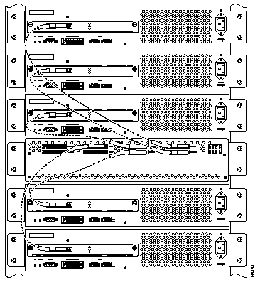
Up to eight Catalyst 3000 units can be connected to a Catalyst Matrix. This configuration requires a stack port cable and a Catalyst Stack Port Module for each Catalyst 3000. The connection is made through one of the eight I/O stack ports on the back panel of the Catalyst Matrix to the single I/O stack port on the Catalyst Stack Port installed in the back of each Catalyst 3000. All of the I/O ports are SCSI-2 type connectors. Use the following instructions (after mounting the Catalyst 3000 units and Catalyst Matrix in a rack or cabinet) to cable the units together.
Step 1 Attach one end of the stack port cable to Port 1 (recommended port to use first) on the Catalyst Matrix. (See Figure 5-7.) It does not matter which end of the cable is used and it does not matter if the Catalyst 3000 or Catalyst Matrix is powered on or off.

Step 2 Attach the other end of the cable to the Catalyst Stack Port connector on the back of a Catalyst 3000 (See Figure 5-8.) Repeat these steps for each Catalyst 3000 using the next highest numbered Catalyst Matrix port (See Figure 5-9.) In Figure 5-8 the Catalyst Matrix port is shown as the fourth unit from the top.

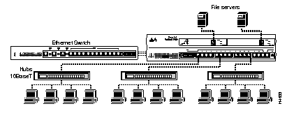
There is one AUI/UTP port, 15 UTP (Unshielded Twisted Pair) ports and two expansion module ports on the front panel of each Catalyst 3000. The UTP ports are 10Base-T using RJ-45 connectors. Use these ports to connect to computers, hubs, servers, and other network devices, or to a network backbone. Figure 5-9 shows examples of Ethernet switches, devices, and networks connected to the Catalyst 3000 ports.
MDI (Media Dependent Interface, or "straight cable") is the IEEE 10Base-T standard for the UTP cable interface. For two 10Base-T devices to communicate with each other, the transmitter of each device must be connected to the receiver of the other device. You can achieve this connection by using a crossover cable, or by using a port that implements the crossover internally. Ports that implement the crossover internally are called MDI-X; "X" stands for crossover.
UTP ports 1 through 15 on the Catalyst 3000 are always MDI-X mode.
When connecting devices that have the same port type, that is, both are MDI or both are MDI-X, use a cross-over cable. For example, when connecting hubs and concentrators that have MDI-X ports to the MDI-X ports on the Catalyst 3000, use a cross-over cable.
When connecting devices that have different port types, that is, one is MDI and one is MDI-X, use a straight cable. For example, servers, PCs, routers, bridges or similar equipment use MDI type ports, therefore use a straight cable to connect these MDI ports to the MDI-X ports on the Catalyst 3000.
See the pinouts in "Appendix A" if a crossover cable needs to be made.
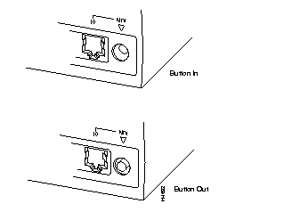
Port 16 can be set on the Catalyst 3000 to either MDI or MDI-X by using the push-button to the right of that port. Refer to the following table (Table 5-1) and illustration (Figure 5-11) to make sure the button is set correctly.
| Push-button | Mode |
| In (below level of front panel) | MDI |
| Out (flush with front panel) | MDI-X |
In Figure 5-11, in the top example, the button is shown in the depressed position.
Because of different combinations of equipment and cables, you should refer to the table below to determine whether you should use the MDI or MDI-X setting:
| Device | Crossover Cable | Straight Cable |
| Hub (MDI-X) | MDI-X | MDI |
| Router | MDI | MDI-X |
| Server | MDI | MDI-X |
If you do need to order, or make a crossover cable, see the pin-outs in Appendix A.
This section explains how to connect a 10Base-T cable to a 10Base-T port on a Catalyst 3000.
 | Caution Do not touch the connector pins of connectors or cables. Static discharge may damage equipment. |
The Catalyst 3000 has 16 10Base-T ports. Connect them as follows:
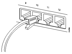
This section explains how to connect to the AUI port on the Catalyst 3000.
 | Caution Do not touch the hub connector pins or the cable connector pins. Static discharge may damage the equipment. |
To connect the AUI port to different media types, use an external transceiver. The Catalyst 3000 supports full-duplex Ethernet when connected to a transceiver supporting full-duplex.
The following section describes how to connect the AUI port on the Catalyst 3000 to an external transceiver.

On Enhanced models, 10BaseT ports on the Catalyst 3000 can be set to either Half-Duplex or Full-Duplex communication mode by the use of DIP switches on the back panel (see Figure 5-14) If the enhanced feature is not configured, then only half-duplex can be used. The enhanced feature must be set and verified through the console. See Chapter 7, "Console Configuration."
Contact your Cisco sales representative for information on how to obtain the enhanced software version.
Use the following four steps to set full-duplex or half-duplex communication modes for 10Base-T ports (1 through 16) on the Catalyst 3000:
Step 1 Locate the DIP switches on the rear panel as illustrated in the following figure:
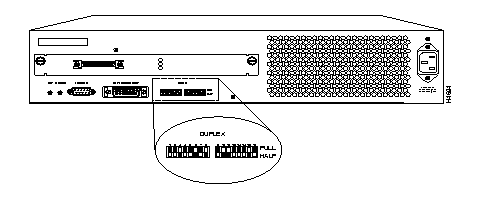
Step 2 Set the DIP switch for each port as follows:
| Half Duplex | Down |
| Full Duplex | Up |
Step 3 When power is applied to the Catalyst 3000, the switch settings will automatically take effect.
Step 4 The settings can be changed while the Catalyst 3000 is running. The new settings take effect right after you change the switch.
The LNK/FDX LED on the front panel is on when a half or full-duplex communications link has been established. The color of the LED responds to whether half or full-duplex:
| Green | Half-Duplex |
| Yellow | Full-Duplex |
Before you apply power, inspect the equipment thoroughly. Verify that all cables are installed correctly. Check their routing, so they are not damaged or create a safety hazard. Be sure all equipment is mounted properly and securely.
 | Warning The chassis does not have an on/off switch. Power is on when the Catalyst 3000 or the Catalyst Matrix is plugged into the power source. There are no user serviceable parts inside the Catalyst 3000. Any internal upgrades or service should be performed by Qualified Personnel ONLY. |
Use the following steps to power on your Catalyst 3000.
Step 1 Ensure that you are using the correct power source.
Step 2 Using the supplied power cable, plug the female end of the cable into the AC receptacle on the Catalyst 3000 or Catalyst Matrix module.
Step 3 Plug the male end of the power cord(s) into a properly grounded electrical outlet.
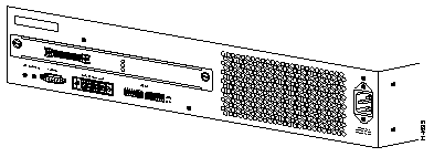
Step 4 Verify that the power (PWR) LED is on. If not, make sure the outlet is working properly. If the outlet is working, but the PWR LED and the fans are not on, see Chapter 11, "Troubleshooting."
Step 5 When the Catalyst 3000 powers on, observe the self-test diagnostic that the unit runs for approximately 6-8 minutes. The DIAG LED is on for the duration of the test, turning off when the self-test is complete.
Step 6 At the completion of the diagnostics, the front panel LEDs should be illuminated according to the status of the unit's configuration.
The following tables list and describe the connectors, switches and status LEDs on the Catalyst 3000.
The following tables list a description of connectors, switches, and status LEDs on the front panel of the Catalyst 3000.
| Name | Description |
|---|---|
| MDI | Sets port 16 to MDI (button in) or MDI-X (button out). Ports 1-15 are always MDI-X. |
The following table lists the rear panel controls on the Catalyst 3000.
The following tables list and provide a description of the connectors, switches, and status LEDs on the Catalyst Matrix.
Table 5-7, Table 5-8, and Table 5-9 list the front panel controls on the Catalyst Matrix.
| Name | Description |
|---|---|
| AC connection | Standard AC power connection. |
| Name | Description |
|---|---|
| SWITCH ID | When pressed, each Catalyst 3000 attached to the Catalyst Matrix will display its box number. |
| ACTIVATE | When the ACTIVATE pushbutton is pressed on an off-line module, it will go on-line and the previous on-line module will go off-line. There is no effect if it is pressed on an on-line module. |
| Name | Color | Description |
|---|---|---|
| READY | Green | Indicates module is fully inserted and powered up. |
| POWER | Green | Indicates module is receiving power. |
| ACTV | Green | ACTIVE LED: On when module is on-line.
Off when off-line. |
Table 5-10 and Table 5-11 list the rear panel controls on the Catalyst Matrix.
| Name | Description |
|---|---|
| PORT1 to PORT8 | SCSI 2 type connectors. For connecting the Catalyst Matrix to Catalyst 3000s to form a stack. |
| Name | Color | Description |
|---|---|---|
| LINK; P1 to P8 | Green | LED off = no link detected.
Green = Shows connection to Catalyst 3000. |
The chassis design allows two Catalyst Matrix modules to be installed; a primary module, and a secondary module for redundancy. Each module contains complete packet switch circuitry, power supply, fan, and AC input power connector. The modules are front accessible and field replaceable.
Internally the chassis contains the I/O backplane and connectors for two modules. Externally, the chassis has I/O connectors and indicators (one per port) for connecting Catalyst 3000 units.
The chassis is 2 RU (Rack Units) in height. The width is 19 inches for rack mounting. The chassis depth is approximately 14 inches.
The following LEDs are on the front panel of the module:
The following push-buttons are on the front panel of the switch module:
The AC input power connector is on the front of each module.
The following LED is on the back panel and is associated with the I/O connectors:
LINK (green) There are eight green LINK LEDs, one per port; P(ort)1 to P8. These LEDs are on only when the port is connected to a powered-on Catalyst 3000.
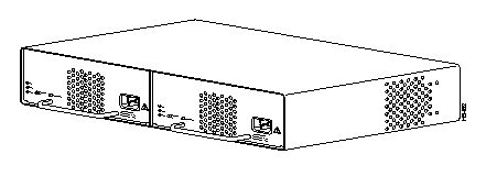
The standard configuration for the Catalyst Matrix includes a chassis and one Catalyst Matrix module (see Figure 5-17). A Catalyst Matrix module includes a fan, power supply, front AC power receptacle, and complete logic circuitry. The Catalyst Matrix chassis needs only one module to operate, but has another slot available for a second, redundant module. If two modules are used, the unit runs with the one on-line (primary) module installed in the left hand side and an off-line (secondary) module installed in the right hand side. If the primary module should fail, Catalyst Matrix operation is switched to the secondary module through automatic logic control. The modules can be also be switched manually using the ACTIVATE push-button on the front panel. For a detailed explanation of the Catalyst Matrix modules, see the section, Catalyst Matrix Module Description, later in this chapter.
The following figure shows the Catalyst 3000 with a Catalyst Matrix module in the left (primary) position and a blank cover plate over the right (secondary) position.

A Catalyst Matrix module can be installed in either the left hand, right hand or both positions of the Catalyst Matrix chassis. If a module fails, it can be easily replaced by the user. The only tool needed is a Phillips or cross-headed screwdriver. The following describes the procedure for adding or replacing a Catalyst Matrix module.
The following steps describe how to install or replace a Catalyst Matrix module.
Use the following steps for installing or replacing a Catalyst Matrix module. If you are installing a module into an open slot proceed to Step 5.
Step 1 If there is a blank cover plate, remove the screw located at the top center and then remove the plate. (Reverse the procedure to install a cover plate.)
Step 2 If removing a module, switch it off-line and disconnect power from the module. (See previous note pertaining to power to the module.)
Step 3 Remove the screw located at the top center of the front of the module.
Step 4 Using the handle on the front of the module, pull the module straight out from the chassis.
Step 5 Insert the module into the open slot. In Figure 5-18 the secondary module is being inserted into the unit. Place the bottom of the module against the bottom of the slot and slide the module into the slot. You should feel some resistance as the module connector mates with the Matrix connector. If you feel solid resistance, pull the module back a little and try again while moving the module slightly to the left or right until you feel the two connectors engage. After the connectors start to engage you should be able to insert the module approximately one-half inch further and then you should feel hard resistance. The connectors should be seated at that point.
Step 6 Install the screw at the top center of the module's front plate.
Step 7 Connect the power cord to the module.
Step 8 To bring this module on-line, press the ACTIVATE push-button.
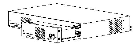
There are two slots in the Catalyst Matrix for modules; a primary slot (normally on-line), and a secondary slot (normally off-line). The modules are hot- swappable. When a secondary module is installed, it provides a redundant module that can be switched on-line if the primary module fails. The primary slot is the one on the left, as viewed from the front of the unit.
Modules switch-over automatically or manually. Automatic switch-over occurs if power fails on the active module or if a primary to secondary switch-over is initiated through any attached Catalyst 3000. Switch-overs can also be initiated manually using the ACTIVATE front panel push-button on the Catalyst Matrix module. Pressing the push-button on the off-line module forces it on-line and the other module to go off-line. The newly activated module assumes the switching functions. The following sections are detailed descriptions of module switch-overs.
Automatic switch-over is initiated when a Catalyst 3000 senses that the primary module has failed. When a failure is detected, any Catalyst 3000 can request the Catalyst Matrix to switch from the primary module to the secondary module. Once the secondary module is on-line, no further switch-over requests are generated by the Catalyst 3000. This one-time switch-over prevents module swap oscillations. The Catalyst 3000 cannot initiate a switch-over from the secondary module to the primary module.
Each Catalyst 3000 periodically sends a packet to itself (self-ping). As long as the packet returns, the on-line Catalyst Matrix module is considered OK. If the self-ping packets do not arrive after a time-out, the on-line module is considered faulty and the Catalyst 3000 requests a module switch-over. The request is via a software controlled request line in the Stack Port link. If a switch-over is requested and the primary module is on-line, the Catalyst Matrix will switch to the secondary module (if present).
A manual switch-over is one that is initiated by the operator. Each module has an ACTIVATE push-button on the front panel. Pressing this push-button on the off-line module turns it on-line (active) and the module that was on-line is forced off-line. Pressing the push-button on the on-line module has no effect.
During a controlled switch-over, data transfer management helps prevent errors. A controlled switch-over is one activated by an Catalyst 3000 (automatic) or by the user push-button (manual).
An uncontrolled switch-over occurs when the on-line module is removed or powered off. Several packets could get corrupted during this time.
If the Catalyst Matrix ports are idle during module switch-over, no packets will be corrupted.
Powering a module on or off, or moving a module has the following effects:
Simultaneous power up - When both modules are installed and powered up at the same time, the primary module will go on-line. The secondary module has a power-up delay that allows the primary module to go on-line first.
Hot insertion - If a second module (primary or secondary) is inserted and powered up after the other module has gone on-line, nothing will happen; the new module will stay off-line and the other will stay on-line.
On-line module powered off or removed - Whether primary or secondary, the remaining module will detect the other's absence and go on-line. (Packet errors may occur with this type of switch-over.)
Both ACTIVATE push-buttons pressed simultaneously - Whichever push-button is pressed first causes its module to go on-line and force the other off-line. In the unlikely case of a tie, the primary module will go on-line.
The following section explains the installation and use of the Catalyst Stack Port connection module, which enables two or more Catalyst 3000 units to work together as a stack.
The Catalyst Stack Port is a single-port expansion module with a special 50-pin connector. If you have two Catalyst 3000 units each equipped with a Catalyst Stack Port module, then when you connect the modules the two Catalyst 3000 units can function as a stack. If you have more than two Catalyst 3000 units each equipped with a Catalyst Stack Port module, you can combine them into a unified Catalyst Stack by connecting each module to a Catalyst Matrix unit. See the section "Connecting Catalyst 3000 Units to the Catalyst Matrix." The Catalyst Matrix supports a stack of up to eight Catalyst 3000 units.
The module can be inserted in its expansion slot as shown in Figure 5-19.
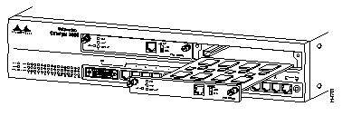
 | Caution Catalyst Stack Port modules are not "hot-swappable." Always be sure that the power is off before installing or removing a Catalyst Stack Port module. If the power is on, damage to the equipment may result. |
| **before**Do not touch the components or connectors on the Catalyst Stack Port module. Do not touch cable connector pins when the other end is plugged in. Damage may result from static discharge.@@before@@ | Caution **after**Do not touch the components or connectors on the Catalyst Stack Port module. Do not touch cable connector pins when the other end is plugged in. Damage may result from static discharge.@@after@@ |
| **before**During installation, the connector on the Catalyst Stack Port module must line up evenly with the connector inside the expansion slot. Mis-alignment may cause the connector pins to bend. When inserting the Catalyst Stack Port module into the expansion slot, be sure that the board is level and that the left and right sides slide evenly into the slot@@before@@ | Caution **after**During installation, the connector on the Catalyst Stack Port module must line up evenly with the connector inside the expansion slot. Mis-alignment may cause the connector pins to bend. When inserting the Catalyst Stack Port module into the expansion slot, be sure that the board is level and that the left and right sides slide evenly into the slot@@after@@ |
Use the following steps when installing a Catalyst Stack Port module into a the rear expansion slot of the Catalyst 3000 chassis.
Step 1 Disconnect the power to the Catalyst 3000.
Step 2 If a blank cover is over the Catalyst Stack Port module slot, remove it by unscrewing its two attachment screws.
Step 3 To prevent possible static damage to the module, hold it by its edges only. Be careful not to touch the top or bottom.
Step 4 Slide the module into the slot evenly, taking care to line up the edges with the guides.
Step 5 Seat the module by pressing the front of the module with your thumbs.
Step 6 Secure the module to the chassis by tightening the thumb (panel) screws at the left and right edges of the expansion modules front panel. Do not overtighten the screws.
Step 7 Return power to the switch.
The Catalyst Stack Port module has a 50-pin SCSI-2 connector designed to accept stack-port cables. These cables are available from your local reseller
The 100Base-TX expansion module is explained in the following sections.
The WS-X3001 is a single-port 100Base-TX expansion module. Use the 100Base-TX to connect to computers, hubs, servers, and other high-speed network devices. The following sections explain the installation, cable connection, and network connection for the 100Base-TX expansion module. For a functional description of the 100Base-TX and the Catalyst 3000, see Chapter 2, "Catalyst 3000 Theory of Operation" in this manual.
The 100Base-TX expansion module is shown in Figure 5-20.

Figure 5-21 is an example of a network connection showing a Catalyst 3000 with two 100Base-TX modules. Each module is linked to an independent high-speed file server.

A Network Interface Card (NIC) is required in some network devices in order to connect them to the 100Base-TX. Several NICs, produced by different manufacturers, have been tested to ensure compatibility and optimum performance between the 100Base-TX and these network devices. For a list of approved NICs, contact your Cisco sales representative.
The modules can be inserted in either of the two expansion slots, as shown in Figure 5-22.
Use the following steps when installing a 100Base-TX module into an expansion slot of the Catalyst 3000 chassis.
 | Caution Expansion modules are not "hot-swappable." Always be sure that the power is off before installing or removing an expansion module. If the power is on, damage to the equipment may result. |
| **before**Do not touch the components or connectors on the expansion module. Do not touch cable connector pins when the other end is plugged in. Damage may result from static discharge.@@before@@ | Caution **after**Do not touch the components or connectors on the expansion module. Do not touch cable connector pins when the other end is plugged in. Damage may result from static discharge.@@after@@ |
| **before**During installation, the connector on the expansion module must line up evenly with the connector inside the expansion slot. Misalignment may cause the connector pins to bend. When inserting the module into the expansion slot, be sure that the board is level and that the left and right sides slide evenly into the slot.@@before@@ | Caution **after**During installation, the connector on the expansion module must line up evenly with the connector inside the expansion slot. Misalignment may cause the connector pins to bend. When inserting the module into the expansion slot, be sure that the board is level and that the left and right sides slide evenly into the slot.@@after@@ |
Step 1 Disconnect the power to the Catalyst 3000.
Step 2 If a blank cover is over the expansion module slot, remove it by unscrewing its two attachment screws.
Step 3 To prevent possible static damage to the module, hold it by its edges only. Be careful not to touch the top or bottom.
Step 4 Slide the module into the slot evenly, taking care to line up the edges with the guides.

Step 5 Seat the module by pressing the front of the module with your thumbs.
Step 6 Secure the module to the chassis by tightening the thumb (panel) screws at the left and right edges of the expansion modules front panel. Do not overtighten the screws.
Step 7 Return power to the switch.
The 100Base-TX module's network port is an RJ-45 connector that uses 100Base-TX cable.
The 100Base-TX module's network port is an RJ-45, 100Base-TX type that is always in MDI-X mode. Cabling the 100Base-TX to different types of equipment that have MDI or MDI-X ports will require different types of 100Base-TX cable. The cable types are described below.
Use the 10Base-T cable information in Appendix A as a reference for 100Base-TX cable.
Connect cables to the RJ-45 port on the front of the 100Base-TX module as follows:
Step 1 Half/full-duplex mode. If the Catalyst 3000 is an enhanced version, see the section "Configuring Full-Duplex Communications" (earlier in this chapter) for a detailed explanation on how to determine whether the communication mode will be half- or full-duplex. The Catalyst 3000 and the 100Base-TX will operate in half-duplex mode only for non-enhanced Catalyst 3000 units. Set the DUPLEX switch on the front of the module to the appropriate position: down for half-duplex, or up for full-duplex. Set to half-duplex only for non-enhanced Catalyst 3000 units.
Step 2 Determine that you have the correct cable. See "Appendix A" for a description of 100Base-TX cables.
Step 3 Connect a 100Base-TX cable from a hub or end-node device to the RJ-45 jack on the front of the expansion module.
Step 4 Insert the cable's 8-pin (RJ-45) plug into the jack until it clicks into place.

When the connection is established, the LNK/FDX LED is on: green in Half-Duplex mode, or yellow in Full-Duplex mode. If the LED is not on, there may be a cable problem. Verify that you are using the correct type of cable, then check if the cable is bad by trying a different one.
If, after installation, there is poor system performance or the 100Base-TX module does not work at all, remove the module and check for any damage or bent connector pins. You may need a bright light to see inside the expansion module slot to check for bent pins. If you cannot find an immediate cause for the problem, refer to Chapter 11, "Troubleshooting."
The following tables describe the connectors, LEDs, and switches on the 100Base-TX module.
| Name | Description |
| Network Port | 8-pin, RJ-45, 100Base-TX |
| Name | Description |
| XMIT | A packet has been transmitted to the attached segment. |
| RCV | A packet has been received from the attached segment. |
| LNK/FDX | Off = link not detected
Green = half-duplex Yellow = full-duplex (Enhanced version only) |
| DIAG | Running diagnostic. |
| Name | Description |
| Duplex | Establishes the communication mode of the network port if the Catalyst 3000 is an enhanced version. Only set to half-duplex for non-enhanced versions.
Full-Duplex (up) or Half-Duplex (down). |
|
|