|
|

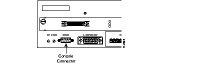
Console interfacing can be established by connecting to the CONSOLE serial port on the back panel of the Catalyst 3000. Use this connection to set up In-band management, which is the management of the Catalyst 3000 "through" the network, or Out-of-band management, which is management "outside" of the network:
NMS application (in-band management) is beyond the scope of this guide. Information is available from the source of the application. How to use the console (out-of-band management) for configuring and monitoring the Catalyst 3000 is described in this chapter in the following topics:
The following steps explain connecting a console to the Catalyst 3000:
Step 1 Connect the Catalyst 3000 to a PC or other DTE (Data Terminal Equipment) device using a straight, 25-pin to 9-pin EIA (RS)-232 cable and a null modem adapter. See Appendix A for a description of the cables and adapters.
Step 2 Connect the EIA-232 cable to the DB-9 connector (console) on the back panel of the Catalyst 3000. The male DB-9 connector on the Catalyst 3000 is configured as a DTE device.
See Figure 6-1 for a view of the cable connection to the back panel of the Catalyst 3000.

The next step is for configuring the console settings for communication with the Catalyst 3000.
Step 3 Use Table 6-1 to set the configuration parameters on the console.
| Baud rate | 2400, 4800, 9600, 19.2K, 38.4K, 57.6K (default: 9600) |
| Parity | None |
| Data bits | 8 |
| Stop bits | 1 |
| Handshaking | None |
| Terminal emulation | VT100 |
| Duplex | Full |
| Soft flow control (XON/XOFF) | Off (input and output) |
| Hard flow control (RTS/CTS) | Off |
| Autobaud upon break | On |
| Line wrap | On |
| Screen scroll | On |
| CR translation | CR |
| Backspace (BS) translation | Destructive |
| Break length (milliseconds) | 350 |
| Enquiry (ENQ) | Off |
| EGA/VGA true underline | Off |
| Terminal width | 890 |
| ANSI 7 or 8 bit commands | 7 |
| Microsoft WindowsTM, terminal emulation | Disable the "Use Function, Arrow, and Ctrl Keys for Windows" option, located in the Terminal Preference menu |
Step 4 At power on (cold boot), the Catalyst 3000 performs a series of self-test diagnostics that verify that hardware components are functioning. An example of the self diagnostic screen is shown later in this chapter.
The three main types of communications problems you may encounter are, no communication, garbled communication, or dropping characters. This section explains how to resolve these problems.
 | Caution Hardware handshaking must be turned on at both the terminal and the Catalyst 3000 and you must have a 7-wire or a 9-wire cable to the terminal. If hardware handshaking is off and you are using a 3-wire cable, a catrostraphic failure of the Catalyst 3000 could occur. |
 | Caution Hardware handshaking must be turned on at both the terminal and the Catalyst 3000 and you must have a 7-wire or 9-wire cable to the terminal. If hardware handshaking is off and you are using a 3-wire cable, a catrostraphic failure of the Catalyst 3000 could occur. |
The diagnostic self-test displays two different screens (lists of information), depending on whether you perform a cold boot (power on cycle with full diagnostics), or a warm boot (a reset without full diagnostics).
During a cold boot, the following comprehensive list of messages appear on the console screen in sequence, as the tests are performed. The warm boot contains portions of this list.
Cisco Catalyst Boot Firmware P/N 57-1327-02, Copyright 1995
- Initiating bootstrapping sequence.
- Boot image integrity check...Passed.
- Control transferred to boot process.
- Relocating main image to DRAM.......Done.
- Main image integrity check...succeeded.
- Control transferred to main process.
Cisco Catalyst 3000 System Software Version 1.1.1-B7, Copyright 1994, 1995.
System started on Fri. November 17, 1995  13:02:46
4 Megabytes System memory
2 Megabytes Network memory
- Initialization started
- File system initialized
- System temperature is within safe operating levels
- Warmboot initialization started
- Checking file system integrity
- LAN ports detected:
  - 10Base-T  : 1 2 3 4 5 6 7 8 9 10 11 12 13 14 15 16
  - StkPort   : 25
- Initializing Ports: 1 2 3 4 5 6 7 8 9 10 11 12 13 14 15 16 25
- Initializing system address table
- No existing diagnostic information, forcing diagnostic mode
- Starting Power Up Diagnostics test
  - UART loopback test on diagnostic port...Passed
  - UART loopback test on console port...Passed
  - RTC memory test...Passed
  - Real Time Clock test...Passed
  - CPU loopback test..............Passed
  - Ethernet Port loopback test...................Passed
  - Ethernet Port fast transmit loopback test...................Passed
  - Ethernet Port fast receive loopback test...................Passed
  - Ethernet Port cross port loopback test...................Passed
  - Ethernet Port broadcast test...................Passed
  - Catalyst Stack Port loopback test...Passed
  - Catalyst Stack Port cross port loopback test...Passed
  - Catalyst Stack Port broadcast test...Passed
  - CPU broadcast test...Passed
- Completed Power Up Diagnostics test
- System entering stand-alone mode
- Catalyst  initiating bootp requests on one or more VLANs
- System initialization complete
- Enabling port: 1 2 3 4 5 6 7 8 9 10 11 12 13 14 15 16 25
Press RETURN key to activate console...
Verify that all diagnostics have passed and that the FAULT LED is off. If the FAULT LED is on, read the screen to determine which test has failed. Power cycle the Catalyst 3000 to re-run the diagnostics to see if that will clear the error. If the error does not clear, see Chapter 11, "Troubleshooting" to help find the cause.
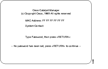
At the end of the boot messages, you should be prompted to press RETURN. The following Greeting screen of the Catalyst 3000 Console Manager should appear.

At the Greeting screen, press RETURN to enter the Main menu. The contents of the Main menu, setting a Password and all information within the menus and sub-menus are described in subsequent chapters. These chapters include configuring, monitoring, and viewing statistics on the Catalyst 3000 Catalyst Stack.
|
|