|
|

Table Of Contents
Catalyst 2955 Switch Power Converter
Overview
This chapter provides these topics that describe the Catalyst 2955 switch, hereafter referred to as the switch.
•
Features
•
Features
The Catalyst 2955 switch is a member of the Catalyst 2950 switch family. Catalyst switches are a series of Ethernet switches that you can use to connect any Ethernet-enabled devices.
The Catalyst 2955 switch is an Ethernet switch that mounts on a DIN rail in an industrial enclosure as well as in a standard 19-inch rack. Its components are designed to withstand extremes in temperature, vibration, and shock so that the switch can be deployed in an industrial environment.
Note
Refer to the switch software configuration guide for examples that show how you might deploy the switches in your network.
Figure 2-1 through Figure 2-3 show the Catalyst 2955 switches.
These are the switch features:
•
–
–
–
•
–
–
–
–
Front-Panel Description
The switch front panel contains the ports, the LEDs, and the power and relay cable connector.
Figure 2-1 to Figure 2-3 show the switch front panels.
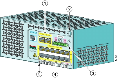
Figure 2-1 Catalyst 2955T-12 Switch
10/100/1000 uplink ports
10/100 ports
Functional ground screw
LEDs
Power and relay connector
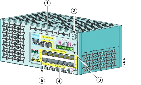
Figure 2-2 Catalyst 2955C-12 Switch
100BASE-FX uplink ports
10/100 ports
Functional ground screw
LEDs
Power and relay connector
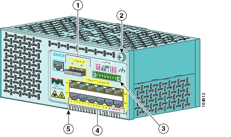
Figure 2-3 Catalyst 2955S-12 Switch
Warning Labels
The laser safety warning label (as shown in Figure 2-4) is on the Catalyst 2955C-12 and 2955S-12 switch front panels. The MM fiber-optic ports on the Catalyst 2955C-12 are Class 1 LEDs. The SM fiber-optic uplink ports on the Catalyst 2955S-12 are Class 1 laser products.
The laser safety warning label means that you should be careful when working with fiber-optic ports and cabling. See Appendix C, "Translated Safety Warnings" for more information about laser safety guidelines.
Figure 2-4 Laser Safety Warning Label
The hot surface warning label (shown in Figure 2-5) is on the Catalyst 2955C-12, 2955S-12, and 2955T-12 switch front panels. This label means that the surface of the switch is hot. See Appendix C, "Translated Safety Warnings," for more information about proper handling guidelines for hot surfaces.
Figure 2-5 Hot Surface Warning Label
10/100 Ports
The 10/100 ports use RJ-45 connectors and twisted-pair cabling. The ports can connect to these devices:
•
•
Note
The 10/100 ports can be set to operate in any combination of half duplex, full duplex, 10 Mbps, or 100 Mbps. They can also be set for speed and duplex autonegotiation, compliant with IEEE 802.3U. In all cases, the cable length from a switch to an attached device cannot exceed 328 feet (100 meters).
When set for autonegotiation, a port senses the speed and duplex settings of the attached device and advertises its own capabilities. If the attached device supports autonegotiation, the port negotiates the best connection (that is, the fastest line speed that both devices support and full-duplex transmission, if the attached device supports it) and configures itself accordingly.
10/100/1000 Ports
The 10/100/1000 uplink ports on the Catalyst 2955T-12 switch use RJ-45 connectors and twisted-pair cabling. The ports can connect to these devices:
•
•
•
Note
Note
The 10/100/1000 ports on the Catalyst 2955T-12 switch can be set to operate at 10 or 100 Mbps at half- or full-duplex mode or 1000 Mbps in full-duplex mode. They can also be set for speed autonegotiation, compliant with IEEE 802.3ab. In all cases, the cable length from a switch to an attached device cannot exceed 328 feet (100 meters).
100BASE-FX Ports
The 100BASE-FX ports on the Catalyst 2955C-12 use 50/125- or 62.5/125-micron MM fiber-optic cabling. In full-duplex mode, the MM fiber-optic cable length from a switch to an attached device cannot exceed 6562 feet (2 kilometers).
For MM connections, you can connect a 100BASE-FX port to a port on a target device by using one of the MT-RJ fiber-optic patch cables listed in Table B-1 on page B-3. Use the Cisco part numbers in Table B-1 to order the patch cables that you need.
100BASE-LX Ports
The 100BASE-LX ports on the Catalyst 2955S-12 use 9/125-micron SM fiber-optic cabling. The cable length from a switch to an attached device cannot exceed 9.375 miles (15 kilometers).
For SM connections, use one of the connectors listed in Table B-2 on page B-4. Use the Cisco part numbers in Table B-2 to order the connectors that you need.
Power and Relay Connector
The power and relay connector provides wire connections to the switch for DC power and configurable alarms (see Figure 2-6). The power and relay connector is to the right of the uplink ports on the faceplate.
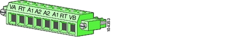
Figure 2-6 Power and Relay Connector
The connector is a pluggable-screw terminal block connector that provides power and return connections for both the primary and secondary power supplies. The positive DC power connection for power supply A is labeled VA, and the return for power supply A is the adjacent connection labeled RT. For power supply B (the redundant power supply), the positive DC power connection is labeled VB, and the return is the adjacent connection labeled RT.
The Catalyst 2955 switch can operate with a single power supply or with dual power supplies. In dual-power mode, the switch draws power from the power supply with higher voltage. If the primary power supply fails in dual-power mode, the alternate power supply gives power to the switch.
Warning
Failure to securely tighten the power and relay connector captive screws can result in an electrical arc if the connector is accidentally removed. Statement 1058
The power and relay connector provides an interface for two independent, normally open (NO) alarm relays. The relays can be triggered by alarms for environmental, power supply, and port status conditions. The relays can be configured to send a fault signal to an external alarm device, such as a bell or a light indicator. You can use the CLI to associate any alarm condition with a single alarm relay or with both relays.
To connect an external alarm device to the relay, you must connect two relay contact wires to complete an electrical circuit. Because each external alarm device requires two connections to a relay, the Catalyst 2955 switch supports a maximum of two external alarm devices.
Note
For more information about the power and relay connector, see Appendix B, "Connectors and Cables."
Note
Console Port
You can connect a switch to a PC through the console port and the supplied RJ-45-to-DB-9 adapter cable. If you want to connect a switch to a terminal, you need to provide an RJ-45-to-DB-25 female DTE adapter. You can order a kit (part number ACS-DSBUASYN=) with that adapter from Cisco Systems. For console-port and adapter-pinout information, see the "Cable and Adapter Specifications" section on page B-5.
Warning
To verify switch operation, perform POST on the switch in a nonhazardous location before installation.Statement 1065
LEDs
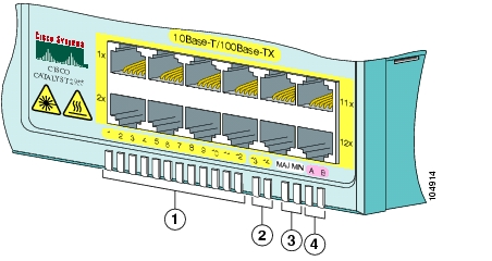
You can use the LEDs to monitor switch activity and performance. The LEDs on all Catalyst 2955 switches are on the bottom edge of the front panel. The LEDs are visible in both face-up and parallel mounting configurations, as shown in Figure 2-7 and Figure 2-8.
Note
All of the LEDs described in this section are visible in the Cluster Management Suite (CMS). The switch software configuration guide describes how to use CMS to configure and to monitor individual switches and switch clusters.
Figure 2-7 LEDs on the Catalyst 2955T-12 Switch
Figure 2-8 LEDs on Catalyst 2955C-12 and Catalyst 2955S-12 Switches
Power Status LEDs
The Catalyst 2955 switch can operate with one or two power supplies. Each power supply input has an associated LED that shows the power supply status.
If the switch is in single-power mode and only power supply A is present and functioning, the LED for power supply B is green, and the LED for power supply A shows its status.
If the switch is in single-power mode and only power supply B is present and functioning, the LED for power supply A is green, and the LED for power supply B shows its status.
In dual-power mode, the switch draws power from the power supply with the higher voltage. If the primary power supply fails in dual-power mode, the alternate power supply gives power to the switch.
The power status LEDs show whether the individual power supplies are receiving power and functioning properly.
Table 2-1 lists the LED colors and meanings.
Note
In dual-power mode, the power status LEDs show status for both power inputs, VA and VB.
Table 2-1 Power Status LEDs
Off
System is not powered up.
Green
Power present on associated contact.
Red
Power not present on associated contact.
For information about the power LED colors during the power-on self-test (POST), see the "Powering On the Switch and Running POST" section on page 3-13.
10/100 Port Status LEDs
Each 10/100 port has a port status LED, also called a port LED, shown in Figure 2-7 and Figure 2-8. These LEDs display information about the switch and the individual ports, shown in Table 2-2.
Uplink Port Status LEDs
The Catalyst 2955 switch has two uplink port status LEDs to the right of the port status LEDs. On the Catalyst 2955C-12 and 2955S-12 switches, the fiber-optic uplink port status LEDs are labeled 13 and 14 (see Figure 2-8). On the Catalyst 2955T-12, the 10/100/1000BASE-T uplink ports are labeled 1 and 2 (see Figure 2-7).
These LEDs display information about the switch and the individual uplink ports, as shown in Table 2-3, Table 2-4, and Table 2-5.
Note
Alarm Relay LEDs
Two alarm relay LEDs labeled MAJ and MIN are to the right of the uplink port status LEDs, as shown in Figure 2-7 and Figure 2-8. These LEDs reflect the state of the major and minor system alarms.
You can use the Cisco IOS command-line interface (CLI) to configure the major and minor LEDs to drive the relay contacts so that the connected external alarm device state mirrors the alarm state of the major (MAJ) or minor (MIN) LED. You can also use the CLI to associate port and global status alarms to one or both relays. Refer to the switch software configuration guide for details.
Warning
An electrical arc can occur when you connect or disconnect the relay wires with field side power applied. This could cause an explosion in switch installations in a hazardous location. Before proceeding, be sure that power is removed or the area is not hazardous. Statement 1061.
Table 2-6 lists the LED colors and meanings.
Note
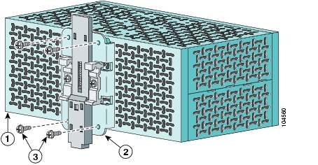
Rear-Panel Description
The rear panel of the Catalyst 2955 switch has a DIN rail mounting clip assembly, as shown in Figure 2-9.
The switch ships with the clip assembly installed on the rear panel, for a parallel mounting configuration.
Figure 2-9 Catalyst 2955 Switch Rear Panel
Catalyst 2955 Switch Power Converter
The Catalyst 2955 switch can be used with an optional AC/DC power converter in a nonhazardous environment. The power converter (PWR-2955-AC=) can supply 24 VDC power in three modes—110 V nominal AC, 220 V nominal AC, and up to 375 VDC (see Table 3-2)—to one or two Catalyst 2955 switches. The power converter is mounted on a DIN rail.
For installation and connection procedures for the power converter, see the "Connecting the Switch to the Power Converter" section on page 3-29.
Caution
Note
Figure 10 shows the power converter.
Figure 10 The Catalyst 2955 Switch AC/DC Power Converter
DC positive connections
AC line connection
DC return connections
AC neutral connection
Earth ground connection
Management Options
Catalyst 2955 switches offer these management options:
•
CMS is made up of three web-based applications that you can use to manage switches. You can use Cluster Builder, which includes Cluster View, and Cluster Manager to create, configure, and monitor switch clusters. You can also use Device Manager to manage individual and standalone switches. For more information, refer to the switch software configuration guide and the CMS online help.
•
You can manage switches by using command-line entries. To access the CLI, connect a PC or terminal directly to the console port on the switch. If the switch is attached to your network, you can use a Telnet connection to manage the switch from a remote location. For more information, refer to the switch command reference.
•
You can use the CiscoView device-management application to set configuration parameters and to view switch status and performance information. This application, which you purchase separately, can be a standalone application or part of an Simple Network Management Protocol (SNMP) network-management platform. For more information, refer to the documentation that came with your CiscoView application.
•
You can manage switches by using an SNMP-compatible management station running platforms such as HP OpenView and SunNet Manager. The switch supports a comprehensive set of MIB extensions and MIB II, the IEEE 802.1D bridge MIB, and four Remote Monitoring (RMON) groups. For more information, refer to the documentation that came with your SNMP application.
•
•
![]()
![]()
![]()
![]()
![]()
![]()
![]()
![]()
Posted: Fri Aug 6 18:43:16 PDT 2004
All contents are Copyright © 1992--2004 Cisco Systems, Inc. All rights reserved.
Important Notices and Privacy Statement.