|
|

Table Of Contents
Cable and Adapter Specifications
Two Twisted-Pair Cable Pinouts
Four Twisted-Pair Cable Pinouts for 10/100 Ports
Four Twisted-Pair Cable Pinouts for 1000BASE-T Ports
Connectors and Cables
This appendix describes the connectors, cables, and adapters that you use to connect the switch to other devices.
Connector Specifications
These sections describe the connectors used with the Catalyst 2955 switches and contain this information:
•
10/100 and 10/100 /1000 Ports
10/100 and 10/100 /1000 Ports
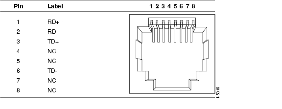
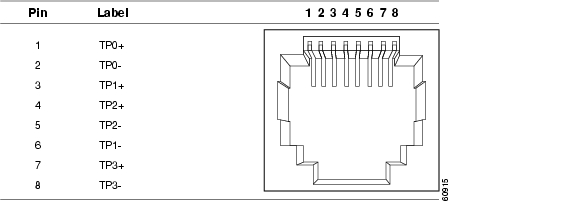
The 10/100 and 10/100/1000 Ethernet ports on Catalyst 2955 switches use standard RJ-45 connectors and Ethernet pinouts with internal crossovers. Figure B-1 and Figure B-2 show the pinouts.
Figure B-1 10/100 Port Pinouts
Figure B-2 10/100/1000 Port Pinouts
100BASE-FX Ports
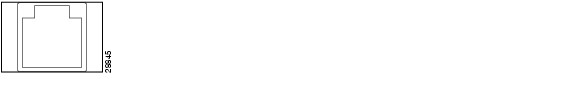
The 100BASE-FX multimode (MM) fiber-optic ports use MT-RJ connectors, shown in Figure B-3. These ports use 50/125- or 62.5/125-micron multimode fiber-optic cabling.
For MM connections, use one of the LCs listed in Table B-1. Use the Cisco part numbers in Table B-1 to order the patch cables that you need.
Figure B-3 MT-RJ Connector
Warning
100BASE-LX Ports
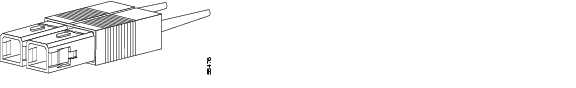
The 100BASE-LX single-mode (SM) fiber-optic ports use LC-type connectors, shown in Figure B-4. These ports use 9/125-micron single-mode fiber-optic cabling.
Figure B-4 100BASE-LX SM Port Connector
Warning
Warning
For SM connections, use one of the LCs listed in Table B-2. Use the Cisco part numbers in Table B-2 to order the connectors that you need.
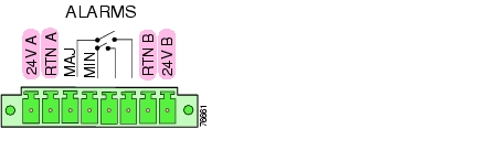
Power and Relay Connector
The power and relay connector is a pluggable-screw terminal block connector that provides power and return connections for both the primary and secondary power supplies. The power and relay connector also gives the Catalyst 2955 switch the interfaces to two independent alarm relays.
Note
Figure B-5 Power and Relay Connector
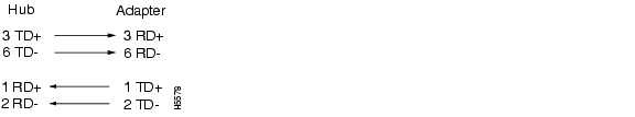
Console Port
The console port uses an 8-pin RJ-45 connector. You can connect a switch to a PC through the console port and the supplied RJ-45-to-DB-9 adapter cable. If you want to connect a switch to a terminal, you need to provide an RJ-45-to-DB-25 female DTE adapter. You can order a kit (part number ACS-DSBUASYN=) with that adapter from Cisco. For console-port and adapter-pinout information, see Table B-3 and Table B-4.
Cable and Adapter Specifications
These sections describe the cables and adapters used with Catalyst 2955 switches.
•
•
•
Two Twisted-Pair Cable Pinouts
Figure B-6 and Figure B-7 show the schematics of two twisted-pair cables for 10/100 ports.
Figure B-6 Two Twisted-Pair Straight-Through Cable Schematic for 10/100 Ports
Figure B-7 Two Twisted-Pair Crossover Cable Schematic for 10/100 Ports
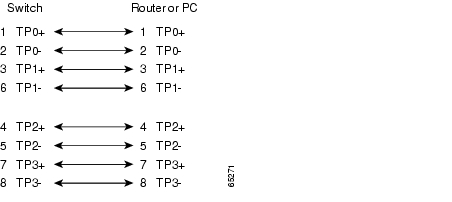
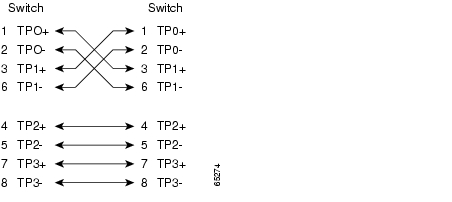
Four Twisted-Pair Cable Pinouts for 10/100 Ports
Figure B-8 and Figure B-9 show the schematics of four twisted-pair cables for 10/100 ports.
Figure B-8 Four Twisted-Pair Straight-Through Cable Schematic for 10/100 Ports
Figure B-9 Four Twisted-Pair Crossover Cable Schematic for 10/100 Ports
Four Twisted-Pair Cable Pinouts for 1000BASE-T Ports
Figure B-10 and Figure B-11 show the schematics of four twisted-pair cables for 10/100/1000 ports on Catalyst 2955T-12 switches and 1000BASE-T ports.
Figure B-10 Four Twisted-Pair Straight-Through Cable Schematic for 10/100/1000 and 1000BASE-T Ports
Figure B-11 Four Twisted-Pair Crossover Cable Schematics for 10/100/1000 and 1000BASE-T Ports
Cable and Adapter Pinouts
This section describes the cable and adapter pinouts and also describes how to identify a rollover cable.
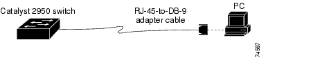
Connecting to a PC
Use the supplied RJ-45-to-DB-9 adapter cable to connect the console port to a PC running terminal-emulation software. Figure B-12 shows how to connect the console port to a PC. Table B-3 lists the pinouts for the console port and the RJ-45-to-DB-9 adapter cable.
Figure B-12 Connecting the Console Port to a PC
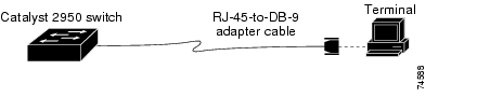
Connecting to a Terminal
Use the supplied RJ-45-to-DB-9 adapter cable and an RJ-45-to-DB-25 female DTE adapter to connect the console port to a terminal. Figure B-13 shows how to connect the console port to a terminal. Table B-4 lists the pinouts for the console port, the adapter cable, and the RJ-45-to-DB-25 adapter.
Note
Figure B-13 Connecting the Console Port to a Terminal
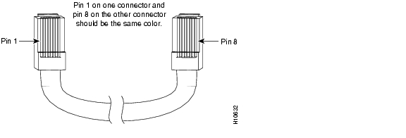
Identifying a Crossover Cable
To identify a crossover cable, compare the two modular ends of the cable. Hold the cable ends side-by-side, with the tab at the back. The wire connected to the pin on the outside of the left plug should be the same color as the wire connected to the pin on the outside of the right plug. (See Figure B-14.)
Figure B-14 Identifying a Crossover Cable
![]()
![]()
![]()
![]()
![]()
![]()
![]()
![]()
Posted: Fri Aug 6 18:35:07 PDT 2004
All contents are Copyright © 1992--2004 Cisco Systems, Inc. All rights reserved.
Important Notices and Privacy Statement.