|
|

Table Of Contents
Configuring the Switch with the CLI-Based Setup Program
Connecting to the Console Port
Starting the Terminal-Emulation Software
Entering the Initial Configuration Information
Configuring the Switch with the CLI-Based Setup Program
This chapter provides a command-line interface (CLI)-based setup procedure for a standalone switch. For product overview information, see Chapter 2, "Overview." Before connecting the switch to a power source, review the safety warnings in Chapter 3, "Installation." For procedures on connecting the switch to a power source, rack-mounting your switch, or connecting to the Ethernet ports, see Chapter 3, "Installation."
CautionIf you are installing your switch in a hazardous environment, review the safety warnings in Chapter 4, "Installation in a Hazardous Environment." For installation procedures for a hazardous environment, see Chapter 4, "Installation in a Hazardous Environment."
These steps describe how to do a simple installation:
2.
3.
4.
5.
Taking Out What You Need
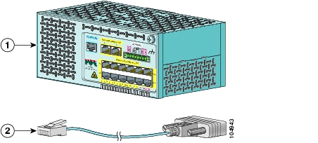
Remove the items shown in Figure 1-1 from the shipping container:
Figure 1-1 Catalyst 2955 Switch and Adapter Cable
Note
Connecting to a Power Source
For instructions on connecting the Catalyst 2955 switch to direct current (DC) power, see the "Wiring the DC Power Source" section on page 3-17. For instructions on connecting the Catalyst 2955 switch to alternating current (AC) or DC power by using the optional power converter, see the "Connecting the Switch to the Power Converter" section on page 3-29.
After the power is applied, the switch automatically begins POST, a series of tests that verifies that the switch functions properly.
Note
When the Catalyst 2955C-12 and 2955S-12 begin POST:
•
•
When the Catalyst 2955T-12 begins POST:
•
•
If POST completes successfully on the Catalyst 2955C-12 and 2955S-12:
•
•
If POST completes successfully on the Catalyst 2955T-12:
•
•
If POST fails on the Catalyst 2955C-12 and 2955S-12:
•
•
If POST fails on the Catalyst 2955T-12:
•
•
If your switch fails POST, see Chapter 5, "Troubleshooting," to determine a corrective action.
Connecting to the Console Port
You can use the console port to perform the initial configuration. To connect the switch console port to a PC, use the supplied RJ-45-to-DB-9 adapter cable.
Warning
Follow these steps to connect the PC or terminal to the switch:
Step 1
Step 2
Figure 1-2 Connecting a Switch to a PC
Starting the Terminal-Emulation Software
Before you power on the switch, start the terminal-emulation session on your PC so that you can see the output display from the power-on self-test (POST).
Warning
To verify switch operation, perform POST on the switch in a nonhazardous location before installation. Statement 1065
The terminal-emulation software—frequently a PC application such as Hyperterminal or ProcommPlus—makes communication between the switch and your PC or terminal possible.
Follow these steps to start a terminal-emulation session:
Step 1
Step 2
•
•
•
•
•
Entering the Initial Configuration Information
To set up the switch, you need to complete the setup program, which runs automatically after the switch is powered on. You must assign an IP address and other configuration information necessary for the switch to communicate with the local routers and the Internet. This information is also required if you plan to use the Cluster Management Suite (CMS) to configure and manage the switch.
IP Settings
You will need this information from your network administrator before you complete the setup program:
•
•
•
•
•
•
Completing the Setup Program
Follow these steps to complete the setup program and to create an initial configuration for the switch:
Step 1
Would you like to enter the initial configuration dialog? [yes/no]:
yes
At any point you may enter a question mark '?' for help.Use ctrl-c to abort configuration dialog at any prompt.Default settings are in square brackets '[]'.Basic management setup configures only enough connectivityfor management of the system, extended setup will ask youto configure each interface on the system.Would you like to enter basic management setup? [yes/no]: yesStep 2
On a command switch, the host name is limited to 28 characters; on a member switch to 31 characters. Do not use -n, where n is a number, as the last character in a host name for any switch.
Enter host name [Switch]: host_nameStep 3
The password can be from 1 to 25 alphanumeric characters, can start with a number, is case sensitive, allows spaces, but ignores leading spaces. The secret password is encrypted, and the enable password is in plain text.
Enter enable secret: secret_passwordStep 4
Enter enable password: enable_password
Note
You can override this warning by re-entering the password or by choosing a different password for the enable secret password.
Step 5
The password can be from 1 to 25 alphanumeric characters, is case sensitive, allows spaces, but ignores leading spaces.
Enter virtual terminal password: terminal-passwordStep 6
Configure SNMP Network Management? [no]: no
Note
Step 7
Enter interface name used to connect to themanagement network from the above interface summary: vlan1Step 8
Configuring interface vlan1:Configure IP on this interface? [yes]: yesIP address for this interface: 10.4.120.106Subnet mask for this interface [255.0.0.0]: 255.0.0.0Step 9
If you enter N, the switch appears as a candidate switch in the CMS. You can configure the switch as a command switch later through the CLI or CMS interface. To configure it later, type no.
Would you like to enable as a cluster command switch? [yes/no]: noYou have now completed the initial configuration of the switch, and the switch displays that configuration. This is an example of the output that appears:
The following configuration command script was created:hostname host_nameenable secret 5 $1$Max7$Qgr9eXBhtcBJw3KK7bc850enable password myline vty 0 15password my_passwordsnmp-server community public!no ip routing!interface Vlan1no shutdownip address 172.20.139.145 255.255.255.224!interface Vlan2shutdownno ip address!interface FastEthernet0/1!interface FastEthernet0/2!...<output abbreviated>!!!interface GigabitEthernet0/1!interface GigabitEthernet0/2!endStep 10
[0] Go to the IOS command prompt without saving this config.[1] Return back to the setup without saving this config.[2] Save this configuration to nvram and exit.If you want to save the configuration and use it the next time the switch reboots, save it in nonvolatile RAM (NVRAM) by selecting option 2.Enter your selection [2]:2Make your selection, and press Return.
After you complete the setup program, the switch can run the default configuration that you created. If you want to change this configuration or want to perform other management tasks, use one of the tools listed in the "Management Options" section on page 2-19.
To use the CLI, enter commands at the Switch> prompt through the console port by using a terminal-emulation program or through the network by using Telnet. For configuration information, refer to the switch software configuration guide or the switch command reference.
To use CMS, refer to the software configuration guide.
![]()
![]()
![]()
![]()
![]()
![]()
![]()
![]()
Posted: Fri Aug 6 18:36:58 PDT 2004
All contents are Copyright © 1992--2004 Cisco Systems, Inc. All rights reserved.
Important Notices and Privacy Statement.