|
|

Table Of Contents
Applying the Switch Protective Liner
Connecting a PC or a Terminal to the Console Port
Powering On the Switch and Running POST
Connecting the Switch to the Power Converter
Installing the Power Converter on a DIN Rail
Connecting the Power Converter to the Power and Relay Connector
Connecting the Power Converter to an AC Power Source
Connecting the Power Converter to a DC Power Source
Applying Power to the Power Converter
Removing the Power Converter from a DIN Rail
Wiring the External Alarm Device Relays
Installing the Switch on a DIN Rail
Installing the Switch in a Rack
Removing the Switch from a DIN Rail or a Rack
Connecting to 10/100 and 10/100/1000 Ports
Connecting to 100BASE-FX MM Ports
Connecting to 100BASE-LX SM Ports
Installation
This chapter describes how to install your switch, interpret the power-on self-test (POST), and connect the switch to other devices.
Note
If your installation is in a hazardous environment, see Chapter 4, "Installation in a Hazardous Environment," for instructions.
Read these topics, and perform the procedures in this order:
•
•
•
•
•
•
•
•
•
Preparing for Installation
This section provides information about these topics:
•
Warnings
These warnings are translated into several languages in Appendix C, "Translated Safety Warnings."
Warning
Warning
Warning
Warning
Warning
Warning
Warning
The enclosure must meet IP 54 or NEMA type 4 minimum enclosure rating standards. Statement 1063
Warning
Warning
Warning
Warning
Warning
Warning
Warning
Warning
Warning
Warning
Warning
Warning
Warning
Warning
Warning
Warning
Warning
Caution
EMC Regulatory Statements
This section includes specific regulatory statements about the Catalyst 2955 family of switches.
U.S.A.
U.S. regulatory information for this product is in the front matter of this manual.
Class A Notice for Taiwan and Other Traditional Chinese Markets
VCCI Class A Notice for Japan
Class A Warning for Korea
Class A Warning for Hungary
Installation Guidelines
When determining where to place the switch, observe these guidelines.
•
•
•
•
•
•
–
–
–
•
•
Note
The temperature inside the enclosure cannot exceed 140oF (60oC), the maximum ambient enclosure temperature of the switch.
•
Verifying Package Contents
Note
The switch is shipped with these items:
•
•
•
•
•
Note
If you want to connect a terminal to the switch console port, you need to provide an RJ-45-to-DB-25 female DTE adapter. You can order a kit (part number ACS-DSBUASYN=) with that adapter from Cisco.
For multimode (MM) connections, you can connect a 100BASE-FX port to a port on a target device by using one of the MT-RJ fiber-optic patch cables listed in Table B-1 on page B-3. Use the Cisco part numbers in Table B-1 to order the patch cables that you need.
For single-mode (SM) connections, you can connect a 100BASE-LX port to a port on a target device by using one of the connectors listed in Table B-2 on page B-4. Use the Cisco part numbers in Table B-2 to order the patch cables that you need.
Applying the Switch Protective Liner
The switch ships with a protective liner that prevents debris from falling into the switch ventilation holes during installation. Before installing the switch on a DIN rail or in a 19-inch rack, connecting the switch to a power source, or wiring the external alarm device relays, you must first apply the protective liner.
Because the protective liner covers ventilation holes on the switch, the liner must be removed from the switch before power is applied to allow proper airflow through the switch chassis.
Follow these steps to apply the protective liner:
Step 1
Step 2
•
•
Caution
Failure to remove the protective liner could result in thermal damage to the switch.
Verifying Switch Operation
Before installing the switch on a DIN rail or in a 19-inch rack, you should power on the switch and verify that the switch passes POST. These sections describe the steps required to connect a PC to the switch console port, to power on the switch, and to observe POST:
Connecting a PC or a Terminal to the Console Port
Powering On the Switch and Running POST
Connecting a PC or a Terminal to the Console Port
To connect a PC to the console port, use the supplied RJ-45-to-DB-9 adapter cable. To connect a terminal to the console port, you need to provide an RJ-45-to-DB-25 female DTE adapter. You can order a kit (part number ACS-DSBUASYN=) with that adapter from Cisco. For console-port and adapter-pinout information, see the "Cable and Adapter Specifications" section on page B-5.
The PC or terminal must support VT100 terminal emulation. The terminal-emulation software—frequently a PC application such as HyperTerminal or Procomm Plus—makes communication between the switch and your PC or terminal possible during the setup program.
Follow these steps to connect the PC or terminal to the switch:
Step 1
Step 2
•
•
•
•
After gaining access to the switch, you can change the port baud rate. Refer to the switch software configuration guide for instructions.
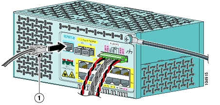
Step 3
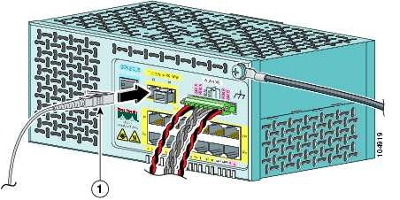
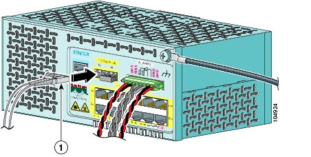
Figure 3-1 Connecting to the Console Port
Step 4
Step 5
Step 6
Powering On the Switch and Running POST
These sections describe the steps required to power on the switch and to observe POST:
Add the Ferrite to the Power and Relay Connector Wiring
Attach the Power and Relay Connector to the Switch
Note
For instructions on how to connect the power converter to the switch, see the "Connecting the Switch to the Power Converter" section.
Locate the power and relay connector, the ferrite, and the switch installation protective liner in the switch kit.
Note
Obtain these necessary tools and equipment:
•
•
•
•
•
–
–
•
Grounding the Switch
Warning
Warning
Caution
To ground the switch to earth ground by using the functional ground screw, follow these steps. Make sure to follow any grounding requirements at your site.
Step 1
Step 2
Figure 3-2 Stripping the Ground Wire
Step 3
Figure 3-3 Crimping the Ring Terminal
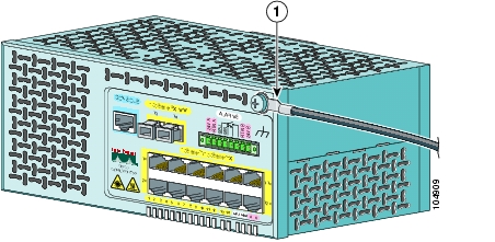
Step 4
Step 5
Step 6
Figure 3-4 Torquing Ground-Lug Screws
Step 7
Wiring the DC Power Source
Warning
Warning
Warning
Caution
Caution
Caution
Note
You must also use the ferrite that ships with the switch.
To wire the switch to the optional AC/DC converter, go to the "Connecting the Switch to the Power Converter" section.
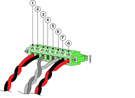
To wire the switch to a DC-input power source, follow these steps:
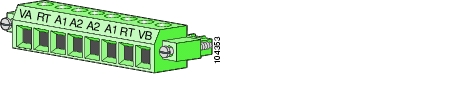
Step 1
Figure 3-5 Power and Relay Connector
Step 2
Step 3
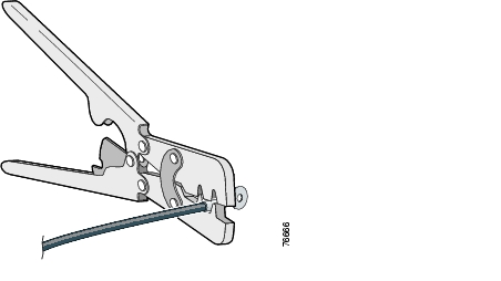
Step 4
Figure 3-6 Stripping the Power Connection Wire
Step 5
Warning
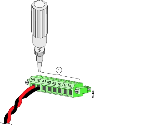
Figure 3-7 Inserting Wires in the Power and Relay Connector
Step 6
Caution
Figure 3-8 Torquing the Power and Relay Connector Captive Screws
Step 7
Note
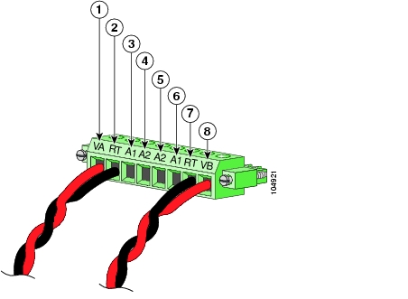
Figure 3-9 shows the completed DC-input wiring on a power and relay connector for a primary power supply and an optional secondary power supply.
Figure 3-9 Completed DC Power Connections on the Power and Relay Connector
Note
Add the Ferrite to the Power and Relay Connector Wiring
Before you connect the power and relay connector to the front panel, follow these steps to add a ferrite to the power and relay connector wiring.
Step 1
Step 2
Figure 3-10 Wire Looped Through the Ferrite
Step 3
Figure 3-11 Clasping the Ferrite
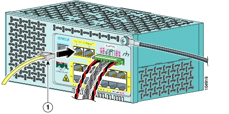
Attach the Power and Relay Connector to the Switch
Follow these steps to attach the power and relay connector to the front panel of the switch.
Step 1
Caution
Figure 3-12 Connecting the Power and Relay Connector to the Switch
Step 2
Power On the Switch
Caution
Failure to remove the protective liner could result in thermal damage to the switch.
To apply power to a switch that is directly connected to a DC power source, locate the circuit breaker on the panel board that services the DC circuit, and switch the circuit breaker to the ON position.
Note
Running POST
After the power is connected, the switch automatically begins POST, a series of tests that verifies that the switch functions properly.
Note
When the Catalyst 2955C-12 and 2955S-12 begin POST:
•
•
When the Catalyst 2955T-12 begins POST:
•
•
If POST completes successfully on the Catalyst 2955C-12 and 2955S-12:
•
•
If POST completes successfully on the Catalyst 2955T-12:
•
•
If POST fails on the Catalyst 2955C-12 and 2955S-12:
•
•
If POST fails on the Catalyst 2955T-12:
•
•
If your switch fails POST, see Chapter 5, "Troubleshooting," to determine a corrective action.
While the switch powers on, the power status LEDs are green or red, showing the presence or absence of power supplies (see Table 2-1 on page 2-13 for details). During POST, the power status LEDs are green. After POST completes successfully, the power status LEDs are green if both power supplies are functioning normally and the switch has been configured to operate in dual-power mode.
If the switch is in single-power mode and only power supply A is present and functioning, the LED for power supply B is green, and the LED for power supply A shows its status. If the switch is in single-power mode and only power supply B is present and functioning, the LED for power supply A is green, and the LED for power supply B shows its status.
Refer to the switch configuration guide for details on single- and dual-power mode operation.
On a Catalyst 2950 switch, you can use the MODE button to recover the switch password. The Catalyst 2955 switch has no MODE button, so the boot loader compensates by using break key detection to stop the automatic boot sequence for password recovery.
On the Catalyst 2955C-12 and 2955S-12 switches, during the initial appearance of the boot loader prompt on the console after POST, uplink port 13 LED blinks green, and uplink port 14 LED is off. On the Catalyst 2955T-12 switch, during the initial appearance of the boot loader prompt on the console after POST, uplink port 1 LED blinks green, and uplink port 2 LED is off.
Note
After successfully running POST, follow these steps.
Step 1
Step 2
Step 3
Connecting the Switch to the Power Converter
The Catalyst 2955 switch can be used with an optional AC/DC power converter (PWR-2955-AC=) in a nonhazardous location installation.
Caution
The power converter requires 1 inch of thermal spacing to prevent overheating. Therefore, there must be a minimum of 4 inches between the power converter and the Catalyst 2955 switch to prevent each device from overheating.
These sections describe the steps required to connect the switch to a power converter:
•
•
After you connect the switch to the power converter, you must connect the power converter to an AC or a DC power source.
For instructions on connecting the power converter to an AC power source, see Connecting the Power Converter to an AC Power Source. For instructions on connecting the power converter to a DC power source, see Connecting the Power Converter to a DC Power Source.
Installing the Power Converter on a DIN Rail
Follow these steps to install the power converter on a DIN rail.
Warning
The enclosure must meet IP 54 or NEMA type 4 minimum enclosure rating standards. Statement 1063
Caution
The power converter requires 1 inch of thermal spacing to prevent overheating. Therefore, there must be a minimum of 4 inches between the power converter and the Catalyst 2955 switch to prevent each device from overheating.
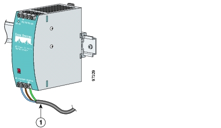
Step 1
Figure 3-13 Mounting the Power Converter on a DIN Rail
Step 2
Step 3
Connecting the Power Converter to the Power and Relay Connector
Follow these steps to connect your switch to the power converter.
Warning
Warning
Caution
Note
You must also use the ferrite that ships with the switch.
Step 1
Step 2
Step 3
Step 4
Step 5
Warning
Step 6
Caution
Step 7
Step 8
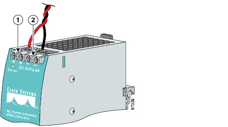
Figure 3-14 Connecting Wires to the Power Converter DC Output Terminal Block
If you are connecting a second power supply, repeat Step 2 through Step 7, using the positive connection (VB) and return connection (RT) on the power and relay connector for power supply B.
Note
Before you connect the power and relay connector to the switch front panel, follow the steps in the "Add the Ferrite to the Power and Relay Connector Wiring" section to add a ferrite to the power and relay connector wiring.
Follow the steps in the "Attach the Power and Relay Connector to the Switch" section to attach the power and relay connector to the front panel of the switch.
Connecting the Power Converter to an AC Power Source
These sections describe the steps required to connect the power converter to an AC power source:
•
Preparing the AC Power Cord
To connect the power converter to an AC power source, you need a standard AC power cord. Power cord connector types vary by country. Check with your electrical equipment supplier to obtain a cord that meets your site electrical requirements. Power cord color codes also vary by country, as shown in Table 3-1.
Table 3-1 AC Power Cord Color Codes
Brown
Line
Blue
Neutral
Green/yellow
Earth ground
Black
Line
White
Neutral
Green
Earth ground
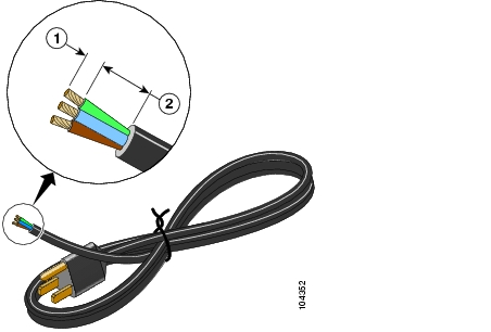
Follow these steps to prepare an AC power cord to connect to the power converter.
Warning
Step 1
Step 2
Step 3
Figure 3-15 Preparing the AC Power Cord
Connecting the AC Power Cord to the Power Converter
Follow these steps to connect the AC power cord to the power converter.
Caution
Step 1
Step 2
Caution
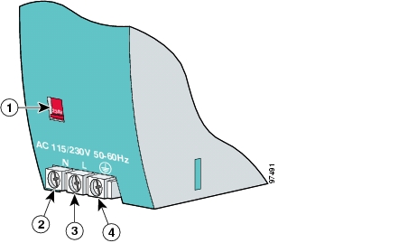
Figure 3-16 AC/DC Power Input Terminal Block and Input Voltage Selector
Input voltage selector
Line wire connection
Neutral wire connection
Earth ground wire connection
Step 3
Step 4
Figure 3-17 Connecting AC Power to the Power Converter
Step 5
Step 6
Table 3-2 lists power converter input voltages and the corresponding input voltage selector settings.
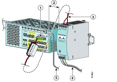
Figure 3-18 shows the completed wiring for the power converter and a Catalyst 2955 switch.
Figure 3-18 The Power Converter Connected to the Catalyst 2955 Switch and an AC Power Source
Power and relay connector
To AC power source
4 inches of thermal spacing
Switch functional ground connection
DC output wires
Connecting the Power Converter to a DC Power Source
You can also connect the power converter to a DC power source. The power converter derates the power source voltage to provide 24 VDC to the switch.
Note
To guarantee 24 VDC at 2.5 A to the Catalyst 2955 switch, the input power to the power converter must remain between 160 and 375 VDC.
Figure 3-19 shows a basic wiring diagram for connecting a power converter to a DC power source.
Figure 3-19 Power Converter Connected to a DC Power Source
DC out
Positive
Power converter
Return
AC/DC input terminal block
Fuse rated to 600 VAC/DC
Earth ground
Fuse rated to 600 VAC/DC
Follow these steps to connect the power converter to a DC power source.
Warning
Warning
Step 1
Note
Step 2
Note
Step 3
Step 4
Step 5
Step 6
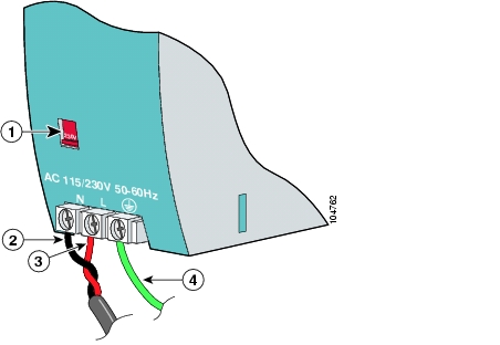
Figure 3-20 AC/DC Power Input Terminal Block Wire Connections to a DC Source
Input voltage selector
Positive wire connection
Return wire connection (to DC return)
Earth ground wire connection
Warning
Step 7
Step 8
Step 9
Step 10
Figure 3-21 shows the completed wiring for the power converter and a Catalyst 2955 switch.
Figure 3-21 The Power Converter Connected to the Catalyst 2955 Switch and a DC Power Source
Power and relay connector
To earth ground
4 inches of thermal spacing
DC input wires
DC output wires
Switch functional ground connection
Applying Power to the Power Converter
Caution
Failure to remove the protective liner could result in thermal damage to the switch.
Move the circuit breaker for the AC outlet or the DC control circuit to the on position.
The LED on the power converter front panel is green when the unit is operating normally. The LED is off when the unit is not operating normally.
After the power is connected, the switch automatically begins the power-on self test (POST), a series of tests that verifies that the switch functions properly. For instructions on how to interpret POST results, see the "Running POST" section.
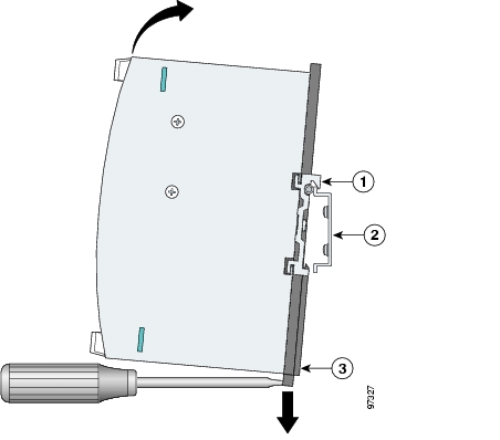
Removing the Power Converter from a DIN Rail
Follow these steps to remove the power converter from a DIN rail.
Step 1
Step 2
Figure 3-22 Removing the Power Converter from a DIN Rail
Wiring the External Alarm Device Relays
The alarm relays on the Catalyst 2955 switch are normally open (NO). To connect an external alarm device to the relays, you must connect two relay contact wires to complete an electrical circuit. Because each external alarm device requires two connections to a relay, the Catalyst 2955 switch supports a maximum of two external alarm devices.
Note
You must also use the ferrite that ships with the switch.
After you have completed the wiring for the power connections, follow these steps to wire the switch to an external alarm device:
Note
Step 1
Step 2
Step 3
Figure 3-23 Inserting Relay Wires into the Power and Relay Connector
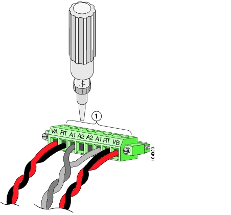
Step 4
Caution
Figure 3-24 Torquing the Power and Relay Connector Captive Screws
Step 5
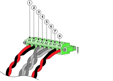
Figure 3-25 shows the completed wiring for two power supplies and two external alarm devices on a power and relay connector.
Figure 3-25 Completed Connections for Two External Alarm Devices on the Power and Relay Connector
Note
See the "Attach the Power and Relay Connector to the Switch" section for instructions on how to connect the power and relay connector to the front panel.
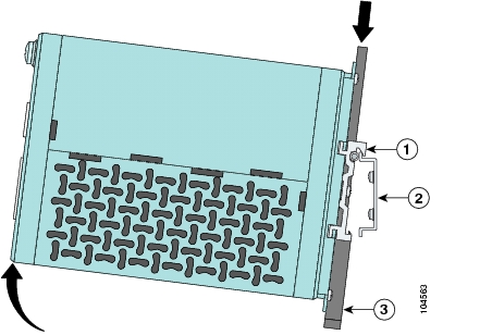
Installing the Switch on a DIN Rail
You can mount the Catalyst 2955 switch on a DIN rail in a parallel or a face-down position.
Warning
The enclosure must meet IP 54 or NEMA type 4 minimum enclosure rating standards. Statement 1063
Caution
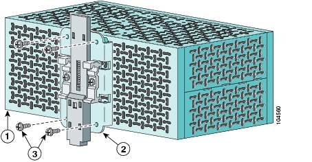
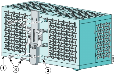
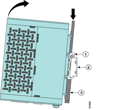
The switch ships with the clip assembly installed on the rear panel for a parallel mounting position, as shown in Figure 3-26. To mount the switch in a face-down position, remove the clip assembly from the rear panel, and install it on the top of the switch, as shown in Figure 3-27.
Figure 3-26 Catalyst 2955 Switch Rear Panel
Figure 3-27 Catalyst 2955 Switch Top Panel
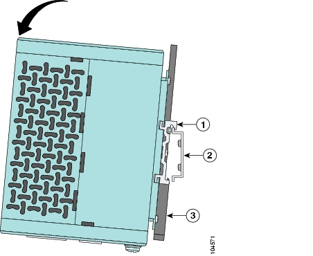
To attach the switch to a DIN rail, follow these steps.
Step 1
Figure 3-28 Mounting the Switch on a DIN Rail in a Parallel Position
Figure 3-29 Mounting the Switch on a DIN Rail in a Face-Down Position
Step 2
Step 3
After the switch is mounted on the DIN rail, power on the switch as described in "Powering On the Switch and Running POST" section.
Note
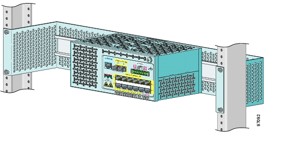
Installing the Switch in a Rack
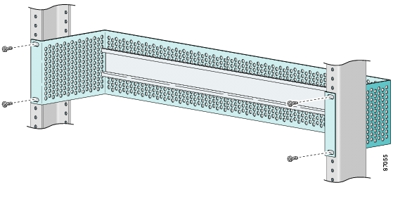
You can use an optional DIN rail adapter kit (available through Cisco, part number STK-RACKMNT-2955=) to mount the Catalyst 2955 switch in a 19-inch rack. The rack mounting kit comes with a DIN rail adapter and screws to attach the adapter to the rack. Ask your Cisco representative for details.
Caution
You can use an optional DIN rail adapter kit (available through Cisco, part number STK-RACKMNT-2955=) to mount the Catalyst 2955 switch in a 19-inch rack. The rack mounting kit comes with a DIN rail adapter and screws to attach the adapter to the rack. Ask your Cisco representative for details.
To install the switch in a rack, follow these steps:
Step 1
Figure 3-30 Installing the DIN Rail Adapter
Step 2
Step 3
Step 4
Figure 3-31 Installing the Switch in a Rack
After mounting the switch in the rack, start the terminal-emulation software, and provide power to the switch. See the "Powering On the Switch and Running POST" section for instructions.
Note
Removing the Switch from a DIN Rail or a Rack
To remove the switch from a DIN rail or a rack, follow these steps:
Step 1
Step 2
Figure 3-32 Removing the Switch from a Parallel Mounting Position
Figure 3-33 Removing the Switch from a Face-Down Mounting Position
Connecting to 10/100 and 10/100/1000 Ports
The 10/100 ports on the Catalyst 2955 configure themselves to operate at the speed and duplex settings of attached devices.They operate at 10 or 100 Mbps in half- or full-duplex mode. If the attached devices do not support autonegotiation, you can set the speed and duplex parameters.
The 10/100/1000 ports configure themselves to operate at the speed setting of attached devices.These ports on the Catalyst 2955T-12 operate at either 10 or 100 Mbps in either full- or half-duplex mode or at 1000 Mbps in full-duplex mode. If the attached devices do not support autonegotiation, you can set the speed parameter.
Connecting devices that do not autonegotiate or devices with manually set speed and duplex parameters can reduce performance or result in link failures between the devices. To maximize performance, choose one of these methods for configuring the ports:
•
•
Caution
Do not touch connectors or pins on component boards. Do not touch circuit components inside the switch. When not in use, store the equipment in appropriate static-safe packaging.
Follow these steps to connect the switch to 10BASE-T, 100BASE-TX, or 1000BASE-T devices:
Step 1
Note
Figure 3-34 Connecting to a 10/100 Port on the Catalyst 2955 Switch
Figure 3-35 Connecting to a 10/100/1000 Port on the Catalyst 2955T-12 Switch
Step 2
Step 3
The LED turns green when the switch and the target device have an established link.
The LED turns amber while Spanning Tree Protocol (STP) discovers the network topology and searches for loops. This process can take about 30 seconds, and then the LED turns green.
If the LED is off, the target device might not be turned on, there might be a cable problem, or there might be a problemg with the adapter installed in the target device. See Chapter 5, "Troubleshooting," for solutions to cabling problems.
Step 4
Step 5
Connecting to 100BASE-FX MM Ports
Warning
The 100BASE-FX MM fiber-optic uplink ports operate in full-duplex mode.
You can connect a 100BASE-FX port to a port on a target device by using one of the MT-RJ fiber-optic patch cables listed in Table B-1 on page B-3. Use the Cisco part numbers in Table B-1 to order the patch cables that you need.
Caution
Follow these steps to connect the switch to a MM 100BASE-FX device:
Step 1
Figure 3-36 Removing Dust Plugs from 100BASE-FX Ports
Step 2
Figure 3-37 Connecting to a 100BASE-FX MM Port
Step 3
Step 4
The LED turns green when the switch and the target device have an established link.
The LED turns amber while STP discovers the network topology and searches for loops. This process can take about 30 seconds, and then the port LED turns green.
If the LED is off, the target device might not be turned on, there might be a cable problem, or there might be a problem with the adapter installed in the target device. See Chapter 5, "Troubleshooting," for solutions to cabling problems.
Step 5
Step 6
Connecting to 100BASE-LX SM Ports
Warning
Warning
You can connect a 100BASE-LX port to a port on a target device by using one of the LC fiber-optic patch cables listed in Table B-2 on page B-4. Use the Cisco part numbers in Table B-2 to order the patch cables that you need.
Follow these steps to connect the switch to a 100BASE-LX SM device:
Caution
Step 1
Figure 3-38 Removing Dust Plugs from 100BASE-LX Ports
Step 2
Figure 3-39 Connecting to a 100BASE-LX SM Port
Step 3
Step 4
The LED turns green when the switch and the target device have an established link.
The LED turns amber while STP discovers the network topology and searches for loops. This process can take about 30 seconds, and then the port LED turns green.
If the LED is off, the target device might not be turned on, there might be a cable problem, or there might be a problem with the adapter installed in the target device. See Chapter 5, "Troubleshooting," for solutions to cabling problems.
Step 5
Step 6
Where to Go Next
For information about starting the switch, refer to the release notes for the Catalyst 2955 switch.
For information about configuring the switch, refer to the switch software configuration guide.
![]()
![]()
![]()
![]()
![]()
![]()
![]()
![]()
Posted: Fri Aug 6 18:46:23 PDT 2004
All contents are Copyright © 1992--2004 Cisco Systems, Inc. All rights reserved.
Important Notices and Privacy Statement.