|
|

This chapter describes routing targets and how to use them. It includes:
After you have classified a call by call type and, if necessary, performed further segmentation, you select the target to receive the call. You can route a call to either a skill target or a network target.
The following are skill targets:
Within a script, you can use a Select, Distribute, or Route Select node to choose from among a set of skill targets. You can also transfer control directly to a specific target based on numerical allocations or other criteria.
Enterprise services and enterprise skill groups are collections of peripheral targets.
The following are network targets:
Within a script, you can route a call directly to any network target.
To set up a target of this type, you first set up a target node that indicates a specific target and route and, then, create a connection directly from an output terminal (success or failure) of any node to the target set.
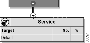
You can use this method at the end of a script after all other efforts to route the call have failed. You might also use it after branching, for example, in an If or Percent Allocation node. However, normally you should rely on a Select node or Distribute node to allocate calls among a set of targets.
 |
Note Although you would normally not use an enterprise service as a target in this way, ICM software would route the call to the first service listed in the enterprise service. Likewise, if you use an enterprise skill group, ICM software routes the call to the first skill group listed in the enterprise skill group. |
The Script Editor contains several nodes that help you determine the best route for a call:
The sections that follow describe each of these nodes and how to use them.
Use the Select node to set up a rule by which ICM software chooses among a set of targets. Rules are based on variables that hold current information about the targets.

You can select a standard rule or define your own custom rule. You can also specify acceptance criteria with either a standard rule or a custom rule.
In addition, you have two choices for evaluation order:
Step 2 Place a target set object (Service, Skill group, or Agents) in the workspace and create a connection from the Select node's success terminal.
 |
Note You must assign at least one target to the target set before you can define a selection rule. |
Step 3 Right-click to open the Select Properties dialog box.
Step 4 Specify the following:
 |
Note If you select the Custom radio button, the Consider If and Select based on fields become activated. See the Custom Selection Rules for information on how to use these fields. |
Step 5 Optionally, enable target requery. See Router Requery for additional information.
Step 6 Optionally, modify the Comments tab.
Step 7 Optionally, modify the Labels tab.
Step 8 Click OK to apply changes and to close the dialog box.
Table 4-1 describes the standard selection rules.
 |
Note Any rule that applies to skill groups can also apply to enterprise skill groups. Any rule that applies to services can also apply to enterprise services. |
| Rule | Targets | What ICM Software Does | Comments |
|---|---|---|---|
Skill groups | Considers if: *.AgentsAvail > 0 Evaluates: MAX (*.LongestAvailable) For each target in the set with available agents, finds the longest time an agent at that target has been continuously available. Chooses the target with the agent who has been available for the longest time. | This rule helps to ensure that all agents in the set are kept equally busy. However, it does not ensure that a specific agent receives the call. | |
Skill groups | Considers if: *.AgentsAvail > 0 Evaluates: MAX (*.AgentsAvail / *.AgentsSignedOn) For each target in the set, finds the number of agents available and the number of agents signed on. Chooses the target with the largest percentage of agents available. | This rule tends to keep all targets equally busy. | |
Services | Evaluates: MIN (*.AvgSpeedAnswerTo5) For each target in the group, finds the target that is, on average, answering calls more quickly. | This rule depends on an average. Consider using another rule, such as Minimum Expected Delay. | |
Services | Evaluates: MIN (*.CallsQNow / *.AgentsReady) For each target in the group, finds the number of calls on hold and the number of stations currently staffed. Chooses the target with the lowest ratio of calls waiting to staffed stations. | This rule calculates the shortest average hold times if agents are equally efficient at each target. However, if the staff for one target is more efficient than another, then some callers might wait longer than necessary at the less efficient target. It might be more efficient to have more calls queued at the more efficient target. Also, if one target tends to handle calls that take longer to process, consider directing callers to another target or another rule, such as Minimum Expected Delay. | |
Services | Evaluates: MIN (*.AvgDelayQTo5) Determines the average time callers spent on hold before reaching an agent. Choose the target with the lowest average. | This rule depends on an average. Consider using another rule, such as Minimum Expected Delay. | |
Services | Evaluates: MIN (*.LongestCallQ) For each target, finds the longest time that a call has currently been on hold waiting for an agent. Chooses the target with the lowest value. | This rule depends on an average. Under heavy call volume, many calls might be routed to a specific service before the longest delayed call value changes. Consider using Minimum Expected Delay instead. | |
Services | Evaluates: MIN (*.ExpectedDelay) For each target, determines the target where the shortest delay is expected. In making this determination, ICM software considers the average handle time, the number of calls in queue, and the number of positions staffed. | By combining current information about calls in queue and staffing levels with historical averages, this rule avoids the potential problems that purely historical rules can cause. This rule is usually the most effective for keeping queue times to a minimum. | |
Maximum Calls in Progress (Max C/P) | Skill groups | Not implemented. | Not implemented. |
Any target | Chooses the first target that passes the acceptance rule specified. | You can set the evaluation order to create a homing hunt (chooses either the first target every time) or a rotary hunt (rotates to the next target each time). |
 |
Warning Values used by the Minimum Average Speed Answer, Minimum Average Queue Delay, and Minimum Longest Delayed Call rules change slowly. Since the averages in these rules only consider what has happened in the past rather than what is currently happening, using these rules inappropriately can lead to load imbalances as newly routed calls have little immediate effect on the values used to route later calls. On the other hand, the Minimum Expected Delay rule takes into account each call as it is routed. Selecting the service with the Minimum Expected Delay usually provides the best balance among the services. |
Instead of using the Standard field in the Select dialog box to choose one of the predefined selection rules, you can use the Custom field to set up your own selection criteria.
A Custom selection rule consists of two expressions that correspond to the two phases of selection:
 |
Note If the Consider If expression is omitted, then all targets in the set are considered. If the Select rule is omitted, then the first target considered is chosen. (The first target depends on the evaluation order specified.) |
You can also use the Accept If field with a custom rule to set up an acceptance rule that must be true for the target to be accepted. If the Accept If rule is not true for the target chosen by the Select formula, then the effect is the same as if no target was selected.
You can set up a rotary or homing hunt by setting the Selection rule to *.Avail>0. The evaluation order you choose determines the type of hunt: rotary (Start With Next Target) or homing (Start With First Target). If only one target meets the Consider If criteria, that target is chosen regardless of the evaluation order. However, if more than one target meets the criteria, then the evaluation order determines which of those targets is chosen.
 |
Note For more information on expressions and the formula editor, see "Formulas". |
The Distribute node allocates calls among the targets in a set based on current information about each target. For example, if you want to distribute calls among a set of services based on the number of agents in the Ready state for each service, services with more Ready agents would get more calls and services with fewer Ready agents would get fewer calls. This keeps the load balanced even as the number of agents logged on and ready varies through shift changes and other activities.
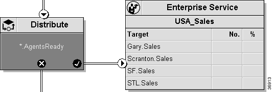
With the Distribute node, you can specify consideration and distribution formulas. The success terminal of the Distribute node connects to a target set, which can be an Agent, Skill Group, Service, Enterprise Skill Group, or Enterprise Service set. If ICM software evaluates the Distribute node's "Consider If" formula to false, no calls are distributed to that target set.
 |
Note For information about the formulas you can specify for each type of target, see "Formulas". |
Step 2 Specify the following:
 |
Note You can access the Formula Editor from each of these fields. |
Step 3 Optionally, modify the Comments tab.
Step 4 Optionally, modify the Labels tab.
Step 5 Click OK to apply changes and to close the dialog box.
The Route Select node combines the functionality of the Select and Distribute nodes while providing you with the flexibility to set different criteria for each target. With the Route Select node, you do not need to include a separate routing target node in the script; all target information is contained within the node.
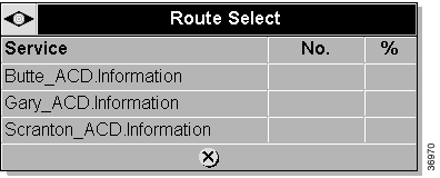
A Select rule in the Route Select node can reference other targets. In the example shown below in Figure 4-5, the Target type is Services, but some Select rules reference skill group data.
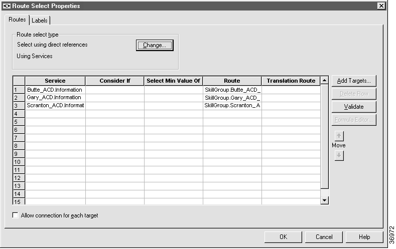
As you set up or modify values in Route Select node, be aware of the following:
Step 2 Click the Change button in the Route Select Type section of the dialog box. The Route Select Type dialog box appears.
Step 3 Select a Target Type (Agent, Enterprise Service, Enterprise Skill Group, Service, or Skill Group).
Step 4 Optionally, select a Business Entity and an Enterprise Target.
Step 5 Specify whether the Route Select node is to act like a Select node or a Distribute node:
Step 6 Specify a Target Reference setting:
Step 7 Click OK to close the Route Select Type dialog box. The label in the Route Select Type section and column names in the Target Type section of the Properties dialog box reflect your changes.
Step 8 Click the Add Targets button. The Add Targets dialog box appears, listing available options for the target type you specified in the Route Select dialog box.
Step 9 Use the Available targets list and the Add button to select targets.
 |
Note If you chose Enterprise Service or Enterprise Skill Group as a target type, you can select just one item from the list. If you chose Agent, Service, or Skill Group, you can select one or more items from the list. |
Step 10 Click OK to close the Add dialog box. The target members you selected appear in the Route Select Properties dialog box.
Step 11 Continue defining Target Type information for each target member:
 |
Note Use a translation route if you want to coordinate external processing with the arrival of the call. (For example, to retrieve customer account information from a database and display it on an agent's screen before a call is answered.) When a call is sent to a translation route, the PG retrieves the final route from ICM software and coordinates the other processing with the external host. |
 |
Note If you enabled target requery, this option is not available. See Router Requery for additional information. |
Step 12 Optionally, enable target requery. See Router Requery for additional information.
Step 13 Optionally, click the Validate button to check the integrity of the table. (For more information on validation, see "Script Editor Overview".)
Step 14 Optionally, modify the Labels tab.
Step 15 Click OK to apply changes and to close the Route Select Properties dialog box.
The Percent Allocation node lets you send a specific percentage of route requests to two or more paths within the script. Each path might lead directly to a target, or you can perform additional processing on one or more paths.
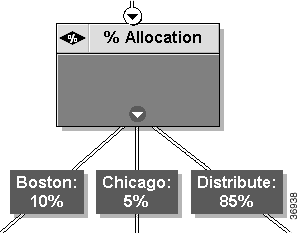
The Percent Allocation node never fails. Each routing request is sent to one of the branches. In the example above, 10% of calls are sent directly to a target in Boston, another 5% are sent directly to a target in Chicago, and the remaining 85% are distributed among a group of targets.
 |
Note If you use a Percent Allocation node to allocate calls among several targets, you lose much of the benefit of call-by-call routing. Usually, it is better to use a Select node or Distribute node to choose among peripheral targets based on real-time conditions at the call centers. Using a Percent Allocation node to distribute calls among targets can result in imbalances. |
 |
Note You must insert targets and connection branches from the Percent Allocation node before you can define the node's properties. |
Step 2 Right-click to open the% Allocation Properties dialog box. The top part of the dialog box displays a column for each output branch, initially assigning a label (A, B, C, etc.) to each branch.
Step 3 To rename an output branch column, select the column name in the Connections field and click the Modify Label button. The label name becomes highlighted and you can make changes.
Step 4 To add a percentage for each connection, click the Modify Percentage button. The percentage value becomes highlighted and you can make changes. (The percentages for all labels must total 100.)
 |
Warning If you ever delete a connection associated with a case, the case information you specified in the Properties dialog box is also deleted. |
Step 5 Optionally, modify the Comments tab.
Step 6 Optionally, modify the Labels tab.
Step 7 Click OK to apply changes and to close the dialog box.
There are two categories of skill targets:
 |
Note For detailed descriptions of each of these nodes, see Script Editor Language Reference. |
After you choose the targets you want to route to, you can then use the Move buttons (up- and down-arrows) on the right side of the dialog box to rearrange the skill groups in the target.
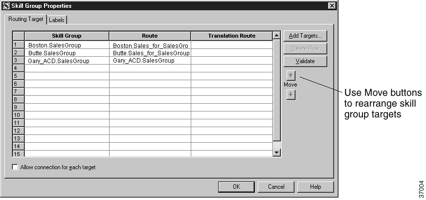
You must also set a route (and optionally a translation route) for each target within the set.
If you specify a translation route, the call is sent to that route first. The Peripheral Gateway associated with that peripheral then retrieves the final route from ICM software. In the meantime, the Peripheral Gateway can coordinate with an external host to perform other processing associated with the call. (For example, the external host might search a database of customer data and send information to the display of the agent that answers the call.)
 |
Note For information on defining routes and associating them with specific targets, see the Cisco ICM Software Configuration Guide. |
The procedure for creating peripheral-level and enterprise-level skill targets is identical.
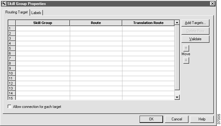
Step 2 Click the Add Targets button. The Add Skill Groups Targets dialog box appears.
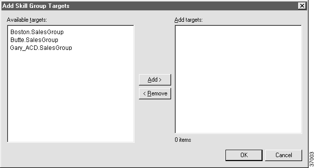
The field on the left lists all the defined services; the field on the right lists those services currently assigned to this target.
Step 3 Select a value from the Available Targets list and click the Add button. Repeat this until all the skill groups you require appear in the Add Targets list.
Step 4 Click OK to add the changes to the Skill Group Properties dialog box.
Step 5 Optionally, rearrange the order of the groups in the list using the Move arrow keys.
 |
Note If you use a rule such as LAA or MED to select from the set, list order has no effect on the routing decision because these rules always consider all targets in the set before making a decision. However, if you use the NAA or Always rule, the order does affect routing decisions because ICM software does not necessarily check all targets in the set before making a decision. |
Step 6 Click a target group member and use the drop-down list in the Route field to associate a route with the target.
Step 7 Optionally, click a target group member and use the drop-down list in the Translation Route field to associate a translation route with the target.
Step 8 Optionally, modify the Labels tab.
Step 9 Click OK to apply changes and to close the dialog box.
Normally, once the script locates a valid target, it returns the route for that target and ends execution. However, you might want to do some processing after the target has been chosen. Usually, this processing is limited to setting variables that are dependent on the target chosen.
To set up additional processing from a skill target, check the Allow Connection For Each Target option in the Routing Target tab of the Properties dialog box. (This option is also available in the Route Select dialog box.)
When this option is checked, an output terminal appears for each element in the routing target.

You can connect one or more elements of the target to additional nodes. After the script processes these nodes, it returns the route for the chosen target as usual.
If you deselect the Allow Connection For Each Target option for a target object, all connections from that target, and their associated nodes, are deleted.
 |
Note This capability is disabled if the target requery function is enabled. See Router Requery 4-21 for additional information. |
The Router Requery feature addresses routing failures due to transient failures in the network (such as network congestion). This feature allows the routing client (a Network Interface Controller (NIC) or a Peripheral Gateway (PG)) to interact with the ICM software CallRouter (router) to determine the appropriate destination for a call. If this destination is available, but not reachable, the Router Requery feature then comes into play to get the call routed. This feature works in the NICM/CICM environment as well.
The requery of the node is intended to cover the following cases:
The routing algorithms are changed on a per call basis, that is, the routing information for one call does not affect the state for other calls. If the first target selected for the call was not reachable, the target is not eliminated from the potential routing destinations for other calls.
In the ICM software system, when queried, the router returns a destination label to the routing client. The routing client then routes the call to the destination specified by the label. If the destination is not reachable (i.e., busy signal or no answer), the call is default routed.
The Router Requery feature provides a mechanism that allows the routing client to requery the router for an alternative label (or labels) in case the destination indicated by the original label is unreachable.
Since this feature is supported through the router, it is not only compatible with translation routing, but does not require special treatment for different failure cases (busy, no answer, route select failure, etc.). However, there are applications (such as Enterprise Agent) where it is important to distinguish between these cases.
The Router Requery feature is implemented using the Label, Queue, RouteSelect, and Select nodes. These script nodes have been modified for this purpose.
If the first choice fails in the network, call processing returns to pick the label corresponding to the second choice in the node.
The router uses the SERVICE_DIVERT_ON_BUSY service type for calls that use requery. The Event Select in the connect message includes a REROUTE_REQUESTED_MASK. When a destination cannot be reached, the NIC queries the router for an alternative destination label.
The call dialog between the routing client and the router continues until either the routing client makes a successful connection; or the router exhausts all possible labels and the failure path for the script node is taken.
In the event of a failure, you can handle requerying in the scripting environment, as you deem appropriate.
You now have the ability to test the error path of these script nodes to determine the specific network cause of failure and conditionally retry the attempt as necessary. This is done using an If node to check the value of the Call variable RequeryStatus. The decision path for the script is then determined by the value of the RequeryStatus variable.
The following are possible values for the RequeryStatus variable:
The execution logic in Label, Queue, Route Select, and Select nodes has been modified so that the router can use it for requery scenarios. Skill Groups, Services or Enterprise Agents can be the targets for these nodes. The RequeryStatus flag indicates the error condition as described in The RequeryStatus Variable. The minor differences as to how various targets are handled are discussed in the following sections.
The label from the Label node is returned to the routing client, and in cases where this label is not accessible, the re-route consists of the Label node failure path.
If Router Requery is enabled, the Label node failure path is available and visible.
If Router Requery is disabled, the Label node failure path is not available and hidden.
The calls in the queue node are sent to the first available target. If the target is not accessible, the router takes the failure path for the Queue node. The script handles the failure path so you can treat the failure path as you wish (i.e., re-queue the call in the same VRU, or sends it to a different target).
These targets can have multiple labels or multiple routes to reach the destination. The router sends up to 9 labels for the selected target. It picks the first 9 labels found. If the routing client determines that the target is not reachable using any of the provided labels, the routing client sends a REROUTE_REQ to the router.
The router then picks the next target in the target list and sends up to 9 labels for the new target. If the second target is also unreachable, the routing client sends another REROUTE_REQ and the router takes the failure path on script node.
If the first target is not reachable, the routing client sends a REROUTE_REQ request. The router then uses the second available agent in the list.
If the second agent is not reachable and if both agents were on the same peripheral, a third agent from a different peripheral is chosen as last try.
If the third agent is also unreachable, the router then uses the failure path of the script node.
The EA PG marks an agent "Not Ready" when the agent is not reachable.
The Script Editor Label, Queue, Route Select, and Select nodes have been modified to provide an option to enable or disable the requery feature.
The RequeryStatus Call variable is available and the value for this variable can be tested at the failure node of the script nodes to see if a requery attempt failed.
The RouteSelect and Target nodes have a property called "Allow connections for each target". This property provides an external connection to other nodes for each target. The requery feature is valid only for nodes with this property disabled so the targets have no continuing connections.
 |
Note The requery feature and use of connections to other nodes are mutually exclusive. If requery is enabled, the targets must not be connected to other script nodes. Script Editor prevents you from creating a target node with outgoing connections and requery enabled. If such situation is found the script validation will fail with an Error. |
The Script Editor contains several network target nodes:
When ICM software executes an Announcement node, the script terminates and ICM software returns the label associated with the announcement to the routing client. The routing client then plays a network announcement for the caller.
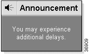
You might use an announcement node to:
 |
Note Before you can use an Announcement node in a script, it must first be configured and assigned a label through the Configuration Manager. For more information, see the Cisco ICM Software Configuration Guide. |
Step 2 Choose the announcement you want to play. If available, descriptive text about the announcement appears in the bottom field of the dialog box.
Step 3 Optionally, modify the Comments tab.
Step 4 Click OK to apply changes and to close the dialog box.
A scheduled target is a destination that can handle a specific number of simultaneous calls based on a periodic schedule. ICM software keeps track of the schedule and the number of calls it sends to the target. The routing client informs ICM software when a call at the target ends. Therefore, ICM software always knows how many calls are currently in progress at the target and whether it can handle an additional call.

 |
Note Not all routing clients support the Scheduled Select node. |
When ICM software executes a Scheduled Select node, it searches the list of selected targets to find one that is capable of handling the call, based on its current schedule.
If a suitable target is found, the routing script ends and returns a label associated with that target to the routing client. The routing client then translates the label to a peripheral target.
 |
Note Before you can use a Schedule Select node in a script, it must first be configured and assigned a label through the Configuration Manager. For more information, see the Cisco ICM Software Configuration Guide. |
Step 2 Use the Evaluation Order radio buttons to specify whether ICM software:
Step 3 Select a value from the Available Scheduled Target list and click the Add button. The target moves to the Selected Targets list.
 |
Note You can select one or more targets for the node. |
Step 4 Optionally, modify the Labels tab.
Step 5 Click OK to apply changes and to close the dialog box.
When ICM software executes a Busy node, it finds the first Busy label configured for the current routing client and returns that label. The routing client then plays a busy signal for the caller.
 |
Note Not all routing clients support the Busy and Ring nodes. |
Likewise, when ICM software executes a Ring node, it finds the first Ring label for the routing client and returns that label. The routing client then plays an unanswered ring for the caller.
 |
Note If you use a Busy or Ring node, you must ensure that you have defined a label of the Busy or Ring type for the routing client. (This procedure is described in the Label Node section below.) |
Within Script Editor, place the Busy or Ring object in the workspace and open the Properties dialog box.
 |
Note There are no properties that need to be set for the Busy or Ring nodes. However, you can use this dialog box to create text that will display on the nodes in the Script Editor. |
Use the Label node to specify a set of valid labels that can be returned to the routing client.
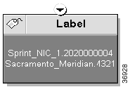
When ICM software executes a Label node, it chooses the first valid label for the current routing client.
 |
Note This differs from the Divert Label node, which returns all the values in the Selected Labels list to the routing client. |
If it finds no valid label, ICM software returns the default label for the dialed number. In either case, the Label node terminates execution of the script.
The Label Properties dialog box displays information about the configured labels in the system. Configured labels are static, defined through the Configuration Manager. A second label type, dynamic labels, is also available. Dynamic labels are expressions the CallRouter processes "on the fly," converting an expression into a character string that is then returned to the routing client as a label.
The dialog box contains two tree structures:
 |
Note If desired, you can sort these lists by Description by clicking on the Description column heading. |
Finally, the Label Information section of the dialog box displays detailed information about the currently selected value in this list.
Step 2 To assign a configured label to this node, do the following:
 |
Note This option is supported only by Intelligent Network routing clients. |
Step 3 To assign a dynamic label to this node, do the following:
Step 4 Optionally, enable target requery. See Router Requery for additional information.
Step 5 Optionally, modify the Comments tab.
Step 6 Click OK to apply changes and to close the dialog box.
Use the Divert Label node to specify a set of valid labels that can be returned to the routing client.

When ICM software executes a Divert Label node, it returns all the values in the Selected Labels list to the routing client.
 |
Note This differs from the Label node, which returns the first valid label for the current routing client. |
ICM software then tries each label until it finds one that does not produce a Busy or Ring Tone No Response.
In most cases, you can specify up to ten labels in the Divert Label node. The exception is in NAM/CICM configurations, where you can specify up to nine labels; one label must be reserved for use by the NAM.
 |
Note This node is not available for all routing clients. |
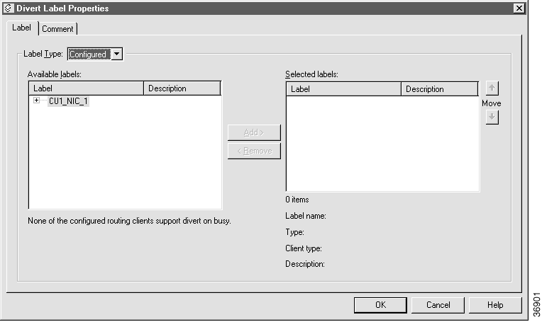
 |
Note Figure 4-15 shows a Divert Label Properties dialog box displaying information about the configured labels in the system. A second label type, dynamic labels, is also available. Dynamic labels are expressions the CallRouter processes "on the fly," converting the expression into a character string that is then returned to the routing client as a label. |
The dialog box contains two tree structures:
 |
Note The Divert Label node only lists the labels for routing clients with client types that support DivertOnBusy. The IPCC client type does not support DivertOnBusy. The following client types do support DivertOnBusy: BT INAP NIC, CRSP, DEUTSCHE TELEKOM, CWC NIC, ENERGIS INAP NIC, AUCS INAP NIC, CAIN, TELFORT INAP, BTV2 INAP NIC, GKTMP NIC, SS7IN NIC, and NTL NIC. |
 |
Note If desired, you can sort these lists by Description by clicking on the Description column heading. |
Finally, the Label Information section displays detailed information about the currently selected value in this list.
Step 2 To assign dynamic labels to this node, do the following:
Step 3 Optionally, modify the Comments tab.
Step 4 To add a label to the list for this node, select the label in the Available Labels list and click the Add button.
Step 5 Optionally, modify the Comments tab.
Step 6 Click OK to apply changes and to close the dialog box.
The Script Editor also contains some nodes that specifically address script termination:
The sections that follow describe each of these nodes and how to use them.
The End node marks a termination point within a script.
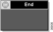
If the script reaches this point, it has failed to find a target for the call and ICM software then uses the default route for the dialed number.
Several End nodes can appear in the same script. The End node is never required; a script can terminate with any node.
Within Script Editor, place the End object in the workspace and open the Properties dialog box.
 |
Note There are no properties that need to set for the End node. However, you can use this dialog box to create text that will display on the node in the Script Editor. |
A Termination node ends a script and specifies how to handle a call. It includes options to invoke a default call processing action or route for the dialed number.
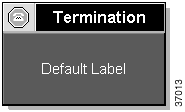
Step 2 Select a termination type:
Step 3 Optionally, modify the Comments tab.
Step 4 Click OK to apply changes and to close the dialog box.
A Release Call node terminates execution of the current routing script and disconnects the caller.
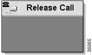
You can use a Release Call node in situations where the caller needs no further service after executing several IVR scripts.
Within Script Editor, place the Release Call object in the workspace and open the Properties dialog box.
 |
Note There are no properties that need to be set for the Release Call node. However, you can use this dialog box to create text that will display on the node in the Script Editor. |
Use the Call Tracer tool to confirm that ICM software is selecting targets as you expect.
The Call Tracer sends routing requests to ICM software and reports on the response. When the Call Tracer sends a request, it reports the script and the specific nodes that the software executes. It also indicates the skill target to which ICM software routes the call.
Figure 4-19 shows some sample results from the Call Tracer.
===========================================================
> DialedNumber (8005551212) using CallType (General_Sales - 6)
Start #3
  Sales\Sales__General (version 2)
Percent allocation #54
  *42% = 0
  16% = 0
  42% = 0
Target #64
  Service: Scranton.Sales R
Route: Scranton.Sales
Peripheral target: DNIS: 1111, Trunk group: Scranton.Incoming800
Label: 2010000000
===========================================================
In Figure 4-19, ICM software invokes a script called sales. It begins with the Start node and then executes a Percent Allocation node that has three branches allocated for 42%, 16%, and 42%, respectively. The asterisk indicates that for this call ICM software choose the first branch. This branch leads to a target that maps to the service Scranton.Sales. Had this been an actual call, the call would have been delivered to that service.
===========================================================

> DialedNumber (8005551212) using CallType (General_Sales - 6)

Start #3

  Sales\Sales__General (version 2)

Percent allocation #54

  42% = 0.416667

  16% = 0.166667

  *42% = 0.375

Target #58

  Service: Gary.Sales

Route: Gary.Sales

Peripheral target: DNIS: 1111, Trunk group: Gary.Incoming800

Label: 3010000000

===========================================================
In Figure 4-20, the new call is counted in the denominator for each branch, but not in the numerator. Therefore, the numbers add up to less than 1.0 (but the total gradually approaches 1.0 as you send more calls). ICM software then picks the branch that is most below its allocation value. In this example, ICM software picked the third branch (because 0.375 is well below the allocation of 42% or 0.42) and would send the call to the Gary.Sales service.
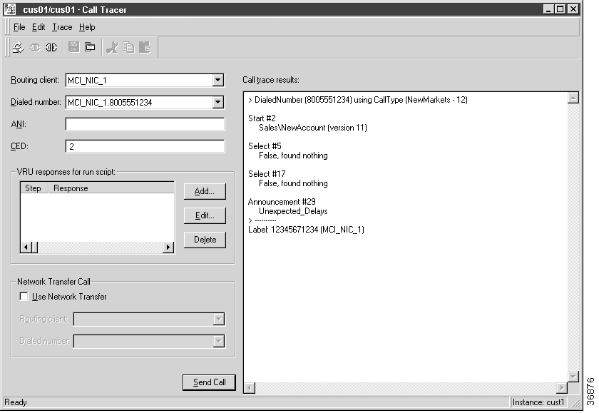
Step 2 Select Trace > Connect. The Call Tracer attempts to establish a connection to a CallRouter and Distributor Admin Workstation. If successful, it then loads the configuration data from the Admin Workstation's local database. Once the configuration is loaded, you can begin tracing a call.
Step 3 In the Call Tracer window, choose a Routing Client and a Dialed Number.
Step 4 Optionally, enter an ANI (caller's telephone number).
Step 5 If you want to test a response from a IVR/VRU routing script, enter values in CED (caller-entered digits) and VRU Responses for Run Script. (For more information see, How to check VRU scripts with the Call Tracer.)
Step 6 If you want to test a Network Transfer call target, click the Use Network Transfer box and then choose a routing client and a dialed number value.
Step 7 Click the Send Call button to submit the request. The results appear in the Call Trace Results field.
Step 8 To send additional calls, optionally change any of the call parameters and then click the Send Call button again. The Call Trace Results field is updated.
 |
Note ICM software executes only installed scripts in response to requests from the Call Tracer. Any uninstalled changes in scripts are not reflected in the Call Tracer results. |
The dialog box below shows an example of a Call Tracer dialog box displaying results.
Step 9 Optionally, select File > Save Trace to save the Call Tracer results.
Step 10 To exit the Call Tracer, choose File > Exit.
The Call Tracer allows you to simulate responses from IVR/VRU routing scripts. For each Script node ICM software encounters, you can specify one of the following responses:
Step 2 Select the type of response (Fail, No Response, Response) the Call Tracer should simulate.
Step 3 If you chose Response in Step 2, optionally specify values to be returned for CED and Variable1 through Variable10.
Step 4 Click OK to apply changes and close the dialog box.
![]()
![]()
![]()
![]()
![]()
![]()
![]()
![]()
Posted: Tue Jun 25 08:26:03 PDT 2002
All contents are Copyright © 1992--2002 Cisco Systems, Inc. All rights reserved.
Important Notices and Privacy Statement.