|
|

This chapter discusses call segmentation in a script. It includes:
Call segmentation is the process of categorizing incoming calls. By examining information about the call, you can determine the type of service the caller requires.
The first information ICM software uses to categorize a call is the call type. (For more information about defining call types, see "Call Types".) Ideally, you should use call types to perform as much of the call segmentation as possible. However, in some cases you might want to perform further segmentation within a routing script. The ICM Software Script Editor makes this possible by providing nodes that let you:
The sections that follow describe these features and how to use them.
ICM software's Script Editor includes nodes that let you refine the call type definition by examining the specific call qualifiers for a call:
Each of these nodes allows you to branch to a connection depending on a value. This allows you to create another level of call segmentation within the script.
For example, you might define a call type for calls from certain area codes in Massachusetts and Pennsylvania. Within the script you can examine the specific calling line ID of the call and alter the classification or routing of the call based on the specific area code from which the call originated.

In this script fragment, the first CLID node segments off calls from the 617 area code for special treatment. The second CLID node segments off calls from the 215 or 412 area code.
 |
Tip You can also use the ClidInRegion built-in function to test whether the CLID value is in a specific region. For information on built-in functions, see "Formulas". |
The Dialed Number (DN) node examines the number dialed by the caller to see whether it matches a value in a list of dialed numbers that you provide.

Step 2 Select the Dialed Numbers to be associated with the node and click the Add button to assign them to the Target Dialed Numbers field.
Step 3 Optionally, click the Comment tab and create descriptive text to appear in the node in the Script Editor.
Step 4 Optionally, modify the Comments tab.
Step 5 Optionally, modify the Labels tab.
Step 6 Click OK to apply changes and to close the dialog box.
The Calling Line ID (CLID) node lets you examine the billing telephone number of the caller to see if it matches:

By default, ICM software compares the list of values against the calling line ID of the call. In practice, however, you are more likely to define a call type that applies to one or more entire area codes or local exchanges.
 |
Note You must insert targets and connection branches from the CLID node before you can define the node's properties. |
Step 2 Right-click to open the CLID Properties dialog box.
Step 3 Use the Case column and Region, Prefix, or Exact Match buttons to specify calling line ID values and specify the connection each value applies to. (The Script Editor automatically sorts the list of CLID values you add.)
 |
Warning If you ever delete a connection associated with a case, the case information you specified in the Properties dialog box is deleted, also. |
Step 4 If you want to specify another value or expression to be used instead of the CLID, click the Variable tab.
Step 5 Click the Use Expression radio button and enter an expression to be used instead of the calling line ID. For each call, the expression you enter will be compared against the list of values in the node.
Step 6 Optionally, modify the Comment tab.
Step 7 Optionally, modify the Labels tab.
Step 8 Click OK to apply changes and to close the dialog box.
The Caller-Entered Digits (CED) node lets you examine the digits entered by the caller in response to prompts to see if they match a specific string. Alternately, you can specify that CEDs are not entered or not required.
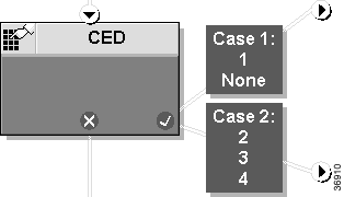
There are two cases where a call might not have a CED value: the caller is not prompted for digits (the CED value is a null string) or the caller was prompted but did not make an entry (the CED value is a hyphen).
 |
Warning If you ever delete a connection associated with a case, the case information you specified in the Properties dialog box is also deleted. |
 |
Note You must insert targets and connection branches from the CED node before you can define the node's properties. |
Step 2 Right-click to open the CED Properties dialog box.
Step 3 Click the Add Digits button. An entry appears in the Case/CED list.
Step 4 Choose the Case (connection number) and do one of the following:
 |
Note Before clicking the No Digits button, choose an option to specify whether the branch applies to either or both of these cases: None applies to both cases, None Entered applies only if the caller was prompted for digits, but did not enter any, None Required applies only if the caller was not prompted for digits. |
Step 5 Optionally, modify the Comment tab.
Step 6 Optionally, modify the Labels tab.
Step 7 Click OK to apply changes and to close the dialog box.
The Time node allows you to branch to two or more connections within a script based on the current time at the ICM Central Controller.

In the example, script control flows to one of three branches depending on the time of day.
The Time node also provides the option of creating an "Otherwise" branch. Call control passes to the Otherwise branch in situations where none of the specific time ranges apply.
 |
Note You must insert targets and connection branches from the Time node before you can define the Time node's properties. |
Step 2 Right-click to open the properties dialog box. The top part of the dialog box displays a column for each output branch (initially assigning a label, A, B, C, etc., to each branch) and a column on the left listing the hours of the day.
Step 3 To add a time range, choose a value in the Connections field and click the Add Time button. The Add Time dialog box appears.
Step 4 Use the Start time and End time scrolling lists to select a time range or ranges (you can create multiple time ranges for each branch). Click OK. The Add time dialog box closes and the range specified for the branch is shown in the Time Ranges field and the Time graph.
Step 5 Optionally, rename an output branch column by selecting the column name in the Connections field and click the Modify Name button. The label name becomes highlighted and you can make changes.
Step 6 Optionally, designate one branch as the Otherwise branch: select a column name in the Connections field and click the Make Otherwise button. The column is renamed Other and assigned no time range.
 |
Warning If you ever delete a connection associated with a case, the case information you specified in the Properties dialog box is also deleted. |
Step 7 Optionally, modify the Comment tab.
Step 8 Optionally, modify the Labels tab.
Step 9 Click OK to apply changes and to close the dialog box.
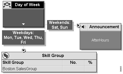
The Day of Week node transfers control to one of several branches depending on the current day of week (Sunday, Monday, etc.). You can define multiple output connections from the Day of Week node and associate each with one or more days of the week.
 |
Note You must insert targets and connection branches from the Day of Week node before you can define the node's properties. |
Step 2 Right-click to open the properties dialog box. The top part of the dialog box displays a column for each output branch (initially assigning a label, A, B, C, etc., to each branch) and a column on the left listing the days of the week.
Step 3 To create a day grid assigning days of the week to output branches, left-click in a spot in the grid to associate a day of week with a connection. A checkmark appears in the grid.
 |
Note You can associate each day of the week with exactly one connection. However, you can associate each connection with one or more days of the week. |
Step 4 Optionally, rename an output branch column by selecting the column name in the Connections field and clicking the Modify Name button. The label name becomes highlighted and you can make changes.
Step 5 Optionally, modify the Comment tab.
Step 6 Optionally, modify the Labels tab.
Step 7 Click OK to apply changes and to close the dialog box.
ICM software includes three nodes that enable you to change the direction of script processing:
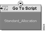
The Go To Script node directs call processing to another script without changing the call type. When ICM software encounters a Go To Script node, it stops executing the current script and starts the script indicated in the node.
 |
Note The Go To Script node has no output connection. |
For example, you might have several scripts that check for exception conditions and, if none are found, execute a standard subroutine. Instead of including that subroutine as a branch from the failure output terminal of each of the exception conditions, you could use a Go To Script node pointing to a separate script containing the subroutine.
 |
Note Within an administrative script, you can go to only another administrative script. Within a routing script, you can go to only another routing script. |
Step 2 Optionally, use the drop-down list to specify a Business Entity.
Step 3 Use the drop-down list to choose the name of the script you want to execute.
Step 4 Optionally, modify the Comment tab.
Step 5 Click OK to apply changes and to close the dialog box.
Right-click the Go To Script node and choose Open Script from the shortcut menu. The referenced script appears in a separate window in Browse Mode.
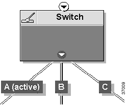
The Switch node directs script execution to its active output connection. You can define multiple output connections from the Switch node; one of them must be specified as the active connection.
 |
Note Only one connection can be active at any time. To change the active branch, you must re-edit the script and create a new script version. |
 |
Note You must insert targets and connection branches from the Time node before defining the Switch node's properties. |
Step 2 Right-click to open the properties dialog box.
The Switch tab displays a row for each output branch, initially assigning a label (A, B, C, etc.) to each branch.
Step 3 Optionally, to rename an output connection, click the Connection label and then click the Modify Name button. The label name becomes highlighted and you can make changes.
Step 4 To make a connection active, click the Connection label and then click the Make Active button. The Script Editor displays Active in the State field for the label.
Step 5 Optionally, modify the Comment tab.
Step 6 Optionally, modify the Labels tab.
Step 7 Click OK to apply changes and to close the dialog box.
The If node directs script execution to one of two branches based on the result of an evaluation.
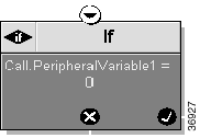
When ICM software executes an If node, it first evaluates the condition specified in the node Properties dialog box's Define condition field. If ICM software determines that the condition is true, control flows through the success output terminal; if it determines the condition is false, control flows through the failure output terminal.
Step 2 Specify the Boolean expression to be evaluated in the Define Condition field.
 |
Note If you want, click the Formula Editor button to access the Formula Editor. See "Formulas" for information on how to use this tool to create expressions. |
Step 3 Optionally, modify the Comment tab.
Step 4 Optionally, modify the Labels tab.
Step 5 Click OK to apply changes and to close the dialog box. (The Script Editor evaluates the expression to ensure that it is valid.)
You can query a row of data from an external SQL Server database within an ICM routing script. For example, if you have a database that contains information about your customers, you might perform a lookup based on the Calling Line ID (that is, the billing telephone number) for the call. Once you have retrieved the row of data, you can reference the columns of that row within the script.
To carry out database lookups of this kind, you must perform the following tasks:
1. Create and populate the external database table.
2. Within the Configuration Manager, enter information about the table and the columns you want to reference.
3. Within the Script Editor, add a DB Lookup node to a routing script.
4. Within the Script Editor, add nodes (such as an If node) referencing database columns accessed by the DB Lookup node.
Create the external SQL Server database using whatever tools you want. However, you must designate a single key column as the SQL primary key. This is the column on which ICM software performs lookups.
After the database table is defined, add data to the table using whatever tools you want.
You might want to maintain two copies of the database: one located with each side of the ICM Central Controller. You can then configure the system so that the active side of the Central Controller always accesses the database located with it.
Next, in the Configuration Manager, you must define the table and specific columns within that table that you want to reference within routing scripts.
 |
Note You need not configure columns that you do not plan to reference. |
Step 2 To enable Add Script Table, click Retrieve.
Step 3 Click Add Script Table. The Script Table property tab appears.
Step 4 In the Name field of the Script Table property tab, enter the database name.
 |
Note The Name field is required. All other fields are optional. For additional information refer to the online Help. |
Step 5 Click Save to apply your changes. The ICM software database manager automatically generates a unique ScriptTableID for each table you define.
Step 2 In the Column Name field enter the name of the new column.
 |
Note The Column Name field is required. All other fields are optional. For additional information refer to the online Help. |
Step 3 Repeat the process for each additional column to be added.
Step 4 Click Save to apply your changes. The ICM software database manager automatically generates a unique ScriptTableColumnID for each column you define.
Within Script Editor, you can use the DB Lookup node to query a specific row of data from an external database. You can then reference columns from that row.
When ICM software executes a DB Lookup node, it does the following:

 |
Note Before you can successfully use DB Lookup in a script, information about the table to be queried must be defined within the Configuration Manager, as described earlier in this chapter. |
 |
Note Script nodes with expressions that refer to external database information may appear in the "success" path extending from the DB Lookup node. In addition, the script must be set up so that any node that references a database column appears after a DB Lookup node is executed. Before DB Lookup retrieves the row, all columns from that table are invalid variables. |
To access retrieved data, use the following syntax in nodes that reference a column:
Database.table-name.column-name
In this syntax:
For example, if the table Customers contains a column named Priority, you would reference that column in an If expression as follows.
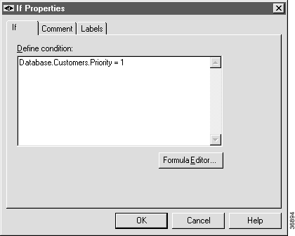
You can also test whether a row has been successfully retrieved before you try to access the data. In this case, the If node would contain the condition:
Database.table-name.Available > 0
If the return value is true (that, is the value is greater than 0), the database information is available. If the return value is false (that is, 0), the database information is not available.
Step 2 Enter values in the following fields:
For example, if the key for the table is a column containing customer telephone numbers, you might enter Call.CallingLineID as the Lookup value.
Step 3 Optionally, modify the Comment tab.
Step 4 Optionally, modify the Labels tab.
Step 5 Click OK to apply changes and to close the dialog box.
An application gateway is an optional ICM feature that allows you to invoke an external application from within a script (using a Gateway node). You can pass data to the application and receive data in return, which you can then examine and use for routing decisions.
Before you can use these nodes in a script, you must first configure the gateways.
The application gateway requires connection information to communicate with the external application. You perform this task using the Configuration Manager.
You must configure an application gateway for each application you want to access from within scripts. Configuration information includes data such as:
| Fault Tolerance Strategy | Description |
|---|---|
Duplicate Request | Each request is sent to both sides of the gateway. |
Alternate Request | Every other request is sent to a different side of the gateway. |
Hot Standby | All requests are sent to only the A side of the gateway unless it fails. Side B is used only if side A is not available. |
None | The application gateway is not duplexed. |
Once you specify the configuration information, you can define the connection information for the gateway, such as the network address of the port through which ICM software communicates with the application.
If your ICM Central Controller is duplexed, you can define separate connection information for each side of the Central Controller. This allows each side to communicate with a local copy of the external application.
 |
Note For a remote ICM, the address must be the same address specified for the ICRP NIC on the targeted system. (You may use the hostname in place of the address.) This address value must be followed by a colon, an instance or customer number (denoting which ICM to access on the remote system), another colon, and a letter indicating which side of the NAM system prefers to use this connection. The preference letters are A (side A of the NAM prefers this connection), B (side B of the NAM prefers this connection), N (neither side of the NAM prefers this connection), or R (both sides of the NAM prefer this connection). For example, the address might be 199.97.123.45:1:A. |
Step 2 To enable Add, click Retrieve.
Step 3 Click Add. The Attributes property tab appears.
Step 4 Complete the Attributes property tab.
 |
Note For additional information refer to the online Help. |
Step 5 Click Save to create the application gateway.
Next, configure the connection information for the application gateway.
Step 2 Complete the Connection property tab(s).
 |
Note For additional information refer to the online Help. |
Step 3 Click Save to apply your changes.
After you have configured an application gateway and its connection information, you can use the Script Editor's Gateway node to reference the external application.
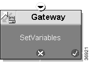
The Gateway node allows you to pass data to the application and receive data in return. You can examine the returned data and use it subsequently in your routing decisions.
When ICM software encounters a Gateway node during script execution, it sends a message through the application gateway. Script execution continues as follows:
Step 2 On the Send tab, specify the following:
Step 3 Click the Receive tab and specify the following:
 |
Note If you select this option, the system will not be able to retrieve any information from the external application. |

Step 4 Optionally, modify the Comment tab.
Step 5 Optionally, modify the Labels tab.
Step 6 Click OK to apply the changes and close the dialog box.
![]()
![]()
![]()
![]()
![]()
![]()
![]()
![]()
Posted: Tue Jun 25 08:24:10 PDT 2002
All contents are Copyright © 1992--2002 Cisco Systems, Inc. All rights reserved.
Important Notices and Privacy Statement.