|
|

This chapter describes the windows that appear in "Service/Subscriber Provisioning" in further details.
The PPPoA-SD Service Profile Configuration window (Figure 10-1) displays two tabs: Configuration and Service Details.
 |
Note See the "PPPoA-Single Domain (SD) Local Termination Service" section for a description of this service type offered by the Cisco 6400 SCM application. |
The Configuration tab (see Figure 10-1) displays three panels:
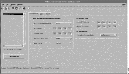
The PPP Session Termination Parameters is a mechanism used by Cisco 6400 UAC to establish or terminate subscriber PPP sessions. The PPP Session Termination Parameters establish incoming subscriber PPP traffic information:
Lower IP Address--The lower limit on the IP address pool.
Higher IP Address--The upper limit on the IP address pool.
No IP address pool is configured when the Higher IP Address and Lower IP Address parameter are left blank.
Subscriber Encapsulation--The IP over ATM encapsulation type used when forwarding traffic to the next hop.
Click Create Profile to create a new service profile with the parameters set in the service profile configuration tabs.
The Service Details tab displays a single Service Description panel.
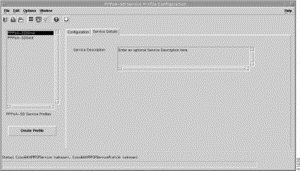
The Service Description panel allows you to enter a description for the service. Entering a Service Description is optional.
Click Create Profile to create a new service profile with the parameters set in the service profile configuration tabs.
 |
Note See the "L2TP Tunnelling Service" section for a description of this service type offered by the Cisco 6400 SCM application. |
The L2TP Service Profile Configuration window (Figure 10-3) displays three tabs: Configuration, Service Details, and QoS Parameters.
The Configuration tab displays three panels: Tunnel Parameters, VC Parameters and Sub-Interface.
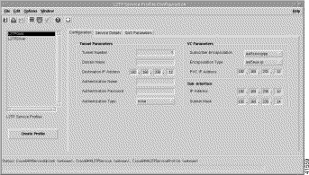
The Tunnel Parameters define the configuration of the tunnel that is created between the sub-interface and the tunnel destination (service):
The VC Class Parameters define the details of the next logical hop in the route to the service network:
The Sub-Interface parameters define a local interface created (on the NRP) to communicate with the service network:
Click Create Profile to create a new service profile with the parameters set in the service profile configuration tabs.
The Service Details tab (Figure 10-4) displays a single Service Description panel.
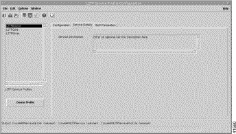
The Service Description panel allows you to enter a description for the service. Entering a Service Description is optional.
The QoS Parameters tab (Figure 10-5) displays two panels: Quality of Service (Receive), and Quality of Service (Transmit).
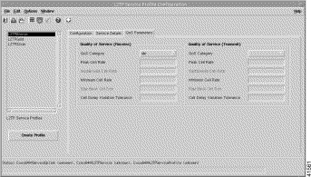
The Quality of Service (Receive) parameters for the egress port are set according to the marketing offering of the carrier (wholesaler) to the upstream service provider.
QoS Category--ATM Quality of Service.
 |
Note Inapplicable parameters are grayed out when a QoS Category is selected. Values are not required for all applicable parameters. For example, values can be entered for the Peak Cell Rate, Minimum Cell Rate, and Cell Delay Variation Tolerance parameters when ubr is the selected QoS Category (but values may not be required for all three parameters). |
Choose values appropriate to your selected QoS category for the following options:
The Quality of Service (Transmit) parameters for the ingress port are set according to the marketing offering of the carrier (wholesaler) to the upstream service provider.
QoS Category--ATM Quality of Service.
 |
Note Inapplicable parameters are grayed out when a QoS Category is selected. Values are not required for all applicable parameters. For example, values can be entered for the Peak Cell Rate, Minimum Cell Rate, and Cell Delay Variation Tolerance parameters when ubr is the selected QoS Category (but values may not be required for all three parameters). |
Choose values appropriate to your selected QoS category for the following options:
Click Create Profile to create a new service profile with the parameters set in the service profile configuration tabs.
The RFC1483 Bridging Service Profile Configuration window (Figure 10-6) displays three tabs: Configuration, Service Details, and QoS Parameters.
 |
Note See the "RFC1483 Bridging Service" section for a description of this service type offered by the Cisco 6400 SCM application. |
The Configuration tab displays three panels:
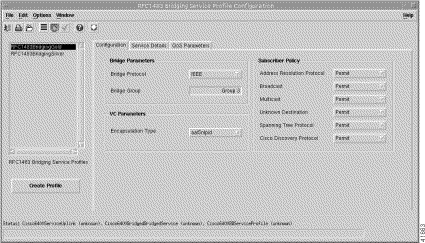
The Bridge Parameters define the details of the bridge group to be created, including the bridge virtual interface:
The VC Parameters define the details of the next logical hop in the route to the service network.
Encapsulation Type--The IP over ATM encapsulation type used when forwarding traffic to the next hop. The following subscriber Encapsulation Types are available: aal5mux ppp (for PPPoE connection type), and aaal5mux ppp or aal5 ciscoppp for a PPPoA connection type.
The Subscriber Policy defines the types of traffic allowed within the bridge group. Traffic types available are, Address Resolution Protocol, Broadcast, Multicast, Unknown Destination, Spanning Tree Protocol, and Cisco Discovery Protocol. Click Permit to allow the traffic type or Deny to disallow the traffic type.
Click Create Profile to create a new service profile with the parameters set in the service profile configuration tabs.
The Service Details tab displays a single Service Description panel.
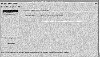
The Service Description panel allows you to enter a description for the service. Entering a Service Description is optional.
Click Create Profile to create a new service profile with the parameters set in the service profile configuration tabs.
The QoS Parameters tab displays two panels: Quality of Service (Receive), and Quality of Service (Transmit).
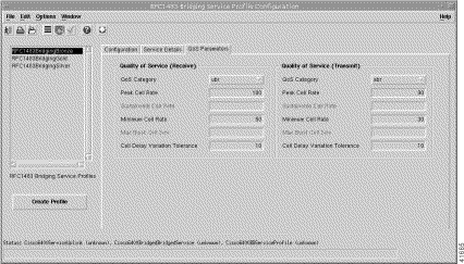
The Quality of Service (Receive) parameters for the egress port are set according to the marketing offering of the carrier (wholesaler) to the upstream service provider.
QoS Category--ATM Quality of Service.
 |
Note Inapplicable parameters are grayed out when a QoS Category is selected. Values are not required for all applicable parameters. For example, values can be entered for the Peak Cell Rate, Minimum Cell Rate, and Cell Delay Variation Tolerance parameters when ubr is the selected QoS Category (but values may not be required for all three parameters). |
Choose values appropriate to your selected QoS category for the following options:
The Quality of Service (Transmit) parameters for the ingress port are set according to the marketing offering of the carrier (wholesaler) to the upstream service provider.
QoS Category--ATM Quality of Service.
 |
Note Inapplicable parameters are grayed out when a QoS Category is selected. Values are not required for all applicable parameters. For example, values can be entered for the Peak Cell Rate, Minimum Cell Rate, and Cell Delay Variation Tolerance parameters when ubr is the selected QoS Category (but values may not be required for all three parameters). |
Choose values appropriate to your selected QoS category for the following options:
Click Create Profile to create a new service profile with the parameters set in the service profile configuration tabs.
The RFC1483 IRB Service Profile Configuration window (Figure 10-9) displays three tabs: Configuration, Service Details, and QoS Parameters.
 |
Note See the "RFC1483 IRB Service" section for a description of this service type offered by the Cisco 6400 SCM application. |
The Configuration tab displays four panels:
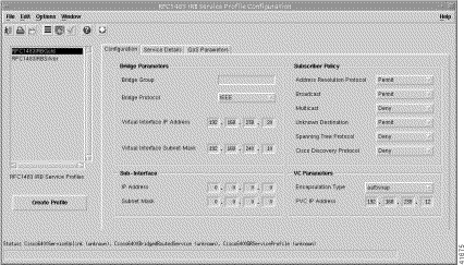
The Bridge Parameters define the details of the bridge group to be created, including the bridge virtual interface:
The Sub-Interface parameters define the details of the bridge group to be created, including the bridge virtual interface:
The Subscriber Policy defines the types of traffic allowed within the bridge group. Traffic types available are, Address Resolution Protocol, Broadcast, Multicast, Unknown Destination, Spanning Tree Protocol, and Cisco Discovery Protocol. Click Permit to allow the traffic type or Deny to disallow the traffic type.
The VC Parameters define the details of the next logical hop in the route to the service network:
Click Create Profile to create a new service profile with the parameters set in the service profile configuration tabs.
The Service Details tab displays a single Service Description panel.
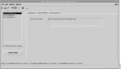
The Service Description panel allows you to enter a description for the service. Entering a Service Description is optional.
Click Create Profile to create a new service profile with the parameters set in the service profile configuration tabs.
The QoS Parameters tab (Figure 10-11) displays two panels: Quality of Service (Receive) and Quality of Service (Transmit) parameters.
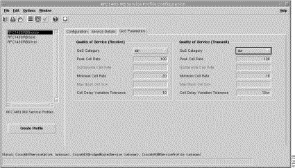
The Quality of Service (Receive) parameters for the egress port are set according to the marketing offering of the carrier (wholesaler) to the upstream service provider.
QoS Category--ATM Quality of Service.
 |
Note Inapplicable parameters are grayed out when a QoS Category is selected. Values are not required for all applicable parameters. For example, values can be entered for the Peak Cell Rate, Minimum Cell Rate, and Cell Delay Variation Tolerance parameters when ubr is the selected QoS Category (but values may not be required for all three parameters). |
Enter values appropriate to your selected QoS category for the following options:
The Quality of Service (Transmit) parameters for the ingress port are set according to the marketing offering of the carrier (wholesaler) to the upstream service provider.
QoS Category--ATM Quality of Service.
 |
Note Inapplicable parameters are grayed out when a QoS Category is selected. Values are not required for all applicable parameters. For example, values can be entered for the Peak Cell Rate, Minimum Cell Rate, and Cell Delay Variation Tolerance parameters when ubr is the selected QoS Category (but values may not be required for all three parameters). |
Choose values appropriate to your selected QoS category for the following options:
Click Create Profile to create a new service profile with the parameters set in the service profile configuration tabs.
The IP Uplink Service Profile Configuration window (see Figure 10-12) displays three tabs: Configuration, Local Service Profile, and QoS Parameters.
 |
Note See the "IP Uplink (for PTA-MD and RBE Subscribers) Service" section for a description of this service type offered by the Cisco 6400 SCM application. |
The Configuration tab displays three panels: Service Description, Local Service Profile, and QoS Parameters.
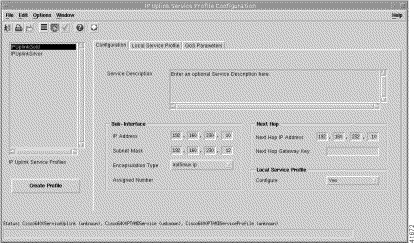
The Service Description panel allows you to enter a description for the service. Entering a Service Description is optional.
The Sub-Interface parameters define a local interface created (on the NRP) to communicate with the service network:
Next Hop IP Address--The IP Address of the next hop in the network.
Next Hop Gateway Key--KEY string to bind next hop IP address to. When the Next Hop Gateway Key is not entered Cisco 6400 SCM binds the next hop IP address to the service profile name.
Configure--Select Yes to enable the Local Service Profile tab. Select No to disable the Local Service Profile tab.
Click Create Profile to create a new service profile with the parameters set in the service profile configuration tabs.
 |
Note You must select Yes within the Local Service Profile panel in the Configuration tab to enable the Local Service Profile tab. |
The Local Service Profile tab (see Figure 10-13) displays three panels: General, DNS Redirection / Tolerance, and Remote RADIUS Configuration.
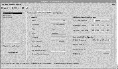
The General panel displays the following information:
The DNS Redirection / Fault Tolerance parameters define the DNS configuration:
The Remote RADIUS Configuration parameters are only available when Proxy is selected as the service Type in the General pane:
Click Create Profile to create a new service profile with the parameters set in the service profile configuration tabs.
The QoS Parameters tab displays two panels:
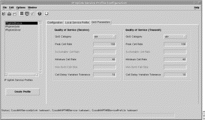
The Quality of Service (Receive) parameters for the egress port are set according to the marketing offering of the carrier (wholesaler) to the upstream service provider.
QoS Category--ATM Quality of Service.
 |
Note Inapplicable parameters are grayed out when a QoS Category is selected. Values are not required for all QoS Categories. For example, values can be entered for the Peak Cell Rate, Minimum Cell Rate, and Cell Delay Variation Tolerance parameters when ubr is the selected QoS Category (but values may not be required for all three parameters). |
Enter values appropriate to your selected QoS category for the following options:
The Quality of Service (Transmit) parameters for the ingress port are set according to the marketing offering of the carrier (wholesaler) to the upstream service provider.
QoS Category--ATM Quality of Service.
 |
Note Inapplicable parameters are grayed out when a QoS Category is selected. Values are not required for all QoS categories. For example, values can be entered for the Peak Cell Rate, Minimum Cell Rate, and Cell Delay Variation Tolerance parameters when ubr is the selected QoS Category (but values may not be required for all three parameters). |
Choose values appropriate to your selected QoS category for the following options:
Click Create Profile to create a new service profile with the parameters set in the service profile configuration tabs.
The Connection Template Configuration window displays a single QoS Parameters tab.
The QoS Parameters tab (Figure 10-15) displays two panels: Quality of Service (Receive), and Quality of Service (Transmit).
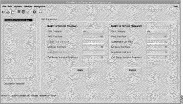
The Quality of Service (Receive) parameters for the egress port are set according to the marketing offering of the carrier (wholesaler) to the upstream service provider.
QoS Category--ATM Quality of Service.
 |
Note Inapplicable parameters are grayed out when a QoS Category is selected. Values are not required for all applicable parameters. For example, values can be entered for the Peak Cell Rate, Minimum Cell Rate, and Cell Delay Variation Tolerance parameters when ubr is the selected QoS Category (but values may not be required for all three parameters). |
Choose values appropriate to your selected QoS category for the following options:
The Quality of Service (Transmit) parameters for the ingress port are set according to the marketing offering of the carrier (wholesaler) to the upstream service provider.
QoS Category--ATM Quality of Service.
 |
Note Inapplicable parameters are grayed out when a QoS Category is selected. Values are not required for all applicable parameters. For example, values can be entered for the Peak Cell Rate, Minimum Cell Rate, and Cell Delay Variation Tolerance parameters when ubr is the selected QoS Category (but values may not be required for all three parameters). |
Choose values appropriate to your selected QoS category for the following options:
 |
Note Connection templates allow you to reconfigure the Quality of Service (Receive) and Quality of Service (Transmit) parameters set for a subscriber without disruption to the service (that is, without having to disconnect a subscriber, change parameters and then reconnect the subscriber. |
Click Apply to save the selected connection template with the parameters configured.
 |
Note Before deleting a connection template you must disconnect all of the subscribers using that connection template. |
Click Delete to delete the selected connection template.
The ATM Service Configuration window (Figure 10-16) displays two tabs: Service Details, and Service Uplink.
 |
Note See the "Pure ATM Switching Service" section for a description of this service type offered by the Cisco 6400 SCM application. |
 |
Note See the tooltips for further descriptions on each of the parameters that follow. Move the mouse pointer over the appropriate parameter and the tooltip description appears. |
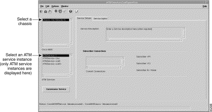
The Service Details tab displays two panels: Service Description and Subscriber Connections.
The Service Description panel allows you to enter a description for the service. Entering a Service Description is optional.
The Subscriber Connections panel displays the following information:
The Service Uplink tab (Figure 10-17) displays a single Service Uplink PVC panel.
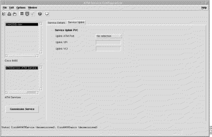
The Service Uplink PVC panel displays the physical line card and port details through which the service is accessed:
Click Commission Service to roll the service onto the Cisco 6400 UAC.
The PPPoA-SD Service Configuration window (Figure 10-19) displays two tabs: Configuration, and Service Details.
 |
Note See the "PPPoA-Single Domain (SD) Local Termination Service" section for a description of this service type offered by the Cisco 6400 SCM application. |
 |
Note See the tooltips for further descriptions on each of the parameters that follow. Move the mouse pointer over the appropriate parameter and the tooltip description appears. |
The Configuration tab (Figure 10-18) displays four panels: PPP Session Termination Parameters, IP Address Pool, VC Parameters, and NRP Selection.
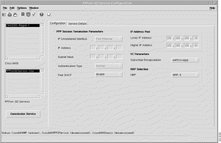
A virtual template is a mechanism used by the Cisco 6400 UAC to establish or terminate subscriber PPP sessions. The PPP Session Termination Parameters establish incoming subscriber PPP traffic information:
Lower IP Address--The lower limit on the IP address pool.
Higher IP Address--The upper limit on the IP address pool.
When the Higher IP Address and Lower IP Address parameter are left blank no IP Address Pool is configured.
Subscriber Encapsulation--The IP over ATM encapsulation type used when forwarding traffic to the next hop.
The NRP Selection panel allows you to select an NRP from the drop down list.
Click Commission Service to roll the service onto the Cisco 6400 UAC.
The Service Details tab (Figure 10-19) displays two panels: Service Description and Subscriber Connections.
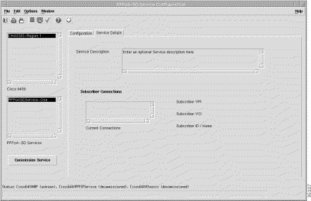
The Service Description panel allows you to enter a description for the service. Entering a Service Description is optional.
The Subscriber Connections panel displays the following information:
Click Commission Service to roll the service onto the Cisco 6400 UAC.
The L2TP Service Configuration window (Figure 10-21) displays three tabs: Configuration, Service Details, and Service Uplink.
 |
Note See the "L2TP Tunnelling Service" section for a description of this service type offered by the Cisco 6400 SCM application. |
 |
Note See the tooltips for further descriptions on each of the parameters that follow. Move the mouse pointer over the appropriate parameter and the tooltip description appears. |
The Configuration tab (Figure 10-20) displays four panels: Tunnel Parameters, VC Parameters, Sub-Interface, and NRP Selection.
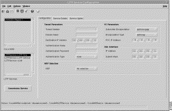
The Tunnel Parameters define the configuration of the tunnel that is created between the sub-interface and the tunnel destination (service):
The VC Class Parameters define the details of the next logical hop in the route to the service network.
Encapsulation Type--The IP over ATM encapsulation type used when forwarding traffic to the next hop. The following subscriber Encapsulation Types are available:
The Sub-Interface Parameters define a local interface created (on the NRP) to communicate with the service network:
The NRP Selection panel allows you to select an NRP from the drop down list.
Click Commission Service to roll the service onto the Cisco 6400 UAC.
The Service Details tab (Figure 10-21) displays three panels: Service Description, NRP Selection, and Subscriber Connections.
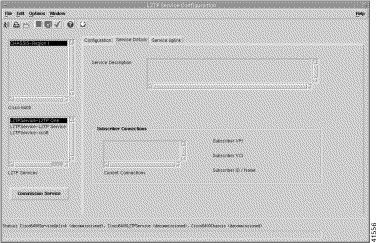
The Service Description panel allows you to enter a description for the service. Entering a Service Description is optional.
The Subscriber Connections panel displays the following information:
The Service Uplink tab (Figure 10-22) displays four panels: Service Uplink PVC, Quality of Service (Receive), Internal NSP/NRP PVC, and Quality of Service (Transmit).
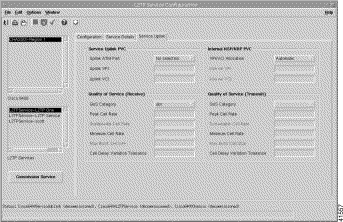
The Service Uplink PVC panel displays the physical line card and port details through which the service is accessed:
The Quality of Service (Receive) parameters for the egress port are set according to the marketing offering of the carrier (wholesaler) to the upstream service provider.
QoS Category--ATM Quality of Service.
 |
Note Inapplicable parameters are grayed out when a QoS Category is selected. Values are not required for all applicable parameters. For example, values can be entered for the Peak Cell Rate, Minimum Cell Rate, and Cell Delay Variation Tolerance parameters when ubr is the selected QoS Category (but values may not be required for all three parameters). |
Choose values appropriate to your selected QoS category for the following options:
The Internal NSP/NRP PVC parameters define the internal PVCs between the NSP and NRP:
The Quality of Service (Transmit) parameters for the ingress port are set according to the marketing offering of the carrier (wholesaler) to the upstream service provider.
QoS Category--ATM Quality of Service.
 |
Note Inapplicable parameters are grayed out when a QoS Category is selected. Values are not required for all applicable parameters. For example, values can be entered for the Peak Cell Rate, Minimum Cell Rate, and Cell Delay Variation Tolerance parameters when ubr is the selected QoS Category (but values may not be required for all three parameters). |
Choose values appropriate to your selected QoS category for the following options:
Click Commission Service to roll the service onto the Cisco 6400 UAC.
The RFC1483 Bridging Service Configuration window (Figure 10-24) displays three tabs: BB Configuration, Service Details, and Service Uplink.
 |
Note See the "RFC1483 Bridging Service" section for a description of this service type offered by the Cisco 6400 SCM application. |
 |
Note See the tooltips for further descriptions on each of the parameters that follow. Move the mouse pointer over the appropriate parameter and the tooltip description appears. |
The Configuration tab (Figure 10-23) displays four panels: Bridge Parameters, VC Parameters, Subscriber Policy, and NRP Selection.
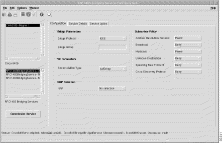
The Bridge Parameters define the details of the bridge group to be created, including the bridge virtual interface:
Encapsulation Type--The IP over ATM encapsulation type used when forwarding traffic to the next hop. The following subscriber Encapsulation Types are available:
The Subscriber Policy defines the types of traffic allowed within the bridge group. Traffic types available are:
Click Permit to allow the traffic type or Deny to disallow the traffic type.
The Service Details tab (Figure 10-24) displays two panels:
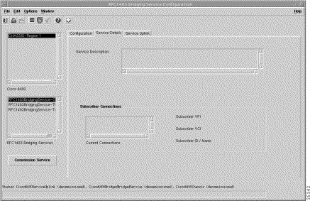
The Service Description panel allows you to enter a description for the service. Entering a Service Description is optional.
The Subscriber Connections panel displays the following information:
The Service Uplink tab (Figure 10-22) displays four panels: Service Uplink PVC, Quality of Service (Receive), Internal NSP/NRP PVC, and Quality of Service (Transmit).
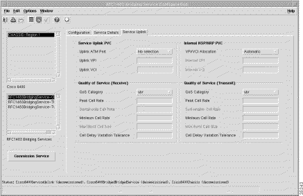
The Service Uplink PVC panel displays the physical line card and port details through which the service is accessed:
The Quality of Service (Receive) parameters for the egress port are set according to the marketing offering of the carrier (wholesaler) to the upstream service provider.
QoS Category--ATM Quality of Service.
 |
Note Inapplicable parameters are grayed out when a QoS Category is selected. Values are not required for all applicable parameters. For example, values can be entered for the Peak Cell Rate, Minimum Cell Rate, and Cell Delay Variation Tolerance parameters when ubr is the selected QoS Category (but values may not be required for all three parameters). |
Choose values appropriate to your selected QoS category for the following options:
The Internal NSP/NRP PVC parameters define the internal PVCs between the NSP and NRP:
The Quality of Service (Transmit) parameters for the ingress port are set according to the marketing offering of the carrier (wholesaler) to the upstream service provider.
QoS Category--ATM Quality of Service.
 |
Note Inapplicable parameters are grayed out when a QoS Category is selected. Values are not required for all applicable parameters. For example, values can be entered for the Peak Cell Rate, Minimum Cell Rate, and Cell Delay Variation Tolerance parameters when ubr is the selected QoS Category (but values may not be required for all three parameters). |
Choose values appropriate to your selected QoS category for the following options:
Click Commission Service to roll the service onto the Cisco 6400 UAC.
The RFC1483 IRB Service Configuration window (Figure 10-27) displays three tabs:
 |
Note See the "RFC1483 IRB Service" section for a description of this service type offered by the Cisco 6400 SCM application. |
 |
Note See the tooltips for further descriptions on each of the parameters that follow. Move the mouse pointer over the appropriate parameter and the tooltip description appears. |
The Configuration tab displays five panels:
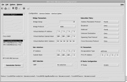
The Bridge Parameters define the details of the bridge group to be created, including the bridge virtual interface:
The Sub-Interface Parameters define a local interface created (on the NRP) to communicate with the service network:
The NRP Selection panel allows you to select an NRP from the drop down list.
The Subscriber Policy defines the types of traffic allowed within the bridge group. Traffic types available are, Address Resolution Protocol, Broadcast, Multicast, Unknown Destination, Spanning Tree Protocol, and Cisco Discovery Protocol. Click Permit to allow the traffic type or Deny to disallow the traffic type.
Encapsulation Type--The IP over ATM encapsulation type used when forwarding traffic to the next hop. The following subscriber Encapsulation Types are available: aal5mux ppp (for PPPoE connection type), and aaal5mux ppp or aal5 ciscoppp for a PPPoA connection type.
Next Hop IP Address--The IP Address of the next hop in the network.
Click Commission Service to roll the service onto the Cisco 6400 UAC.
IP Route -- When set to "Enable"', IP Routing will be switched on for the particular Bridge Group and a route between the Sub-Interface and PVC IP Address will be configured on the device. When set to "Disabled" the routing information must be manually configured on the device using Cisco IOS.
The Service Details tab (Figure 10-27) displays the Service Description panel and the Subscriber Connections panel.
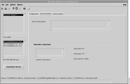
The Service Description panel allows you to enter a description for the service. Entering a Service Description is optional.
The Subscriber Connections panel displays the following information:
The Service Uplink tab displays four panels: Service Uplink PVC, Quality of Service (Receive), Internal NSP/NRP PVC, and Quality of Service (Transmit).
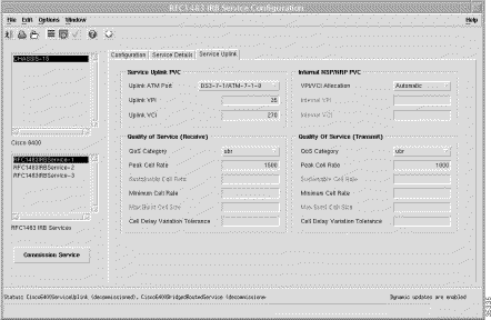
The Service Uplink PVC panel displays the physical line card and port details through which the service is accessed:
The Quality of Service (Receive) parameters for the egress port are set according to the marketing offering of the carrier (wholesaler) to the upstream service provider.
QoS Category--ATM Quality of Service.
 |
Note Inapplicable parameters are grayed out when a QoS Category is selected. Values are not required for all applicable parameters. For example, values can be entered for the Peak Cell Rate, Minimum Cell Rate, and Cell Delay Variation Tolerance parameters when ubr is the selected QoS Category (but values may not be required for all three parameters). |
Choose values appropriate to your selected QoS category for the following options:
The Internal NSP/NRP PVC parameters define the internal PVCs between the NSP and NRP.
The Quality of Service (Transmit) parameters for the ingress port are set according to the marketing offering of the carrier (wholesaler) to the upstream service provider.
QoS Category--ATM Quality of Service.
 |
Note Inapplicable parameters are grayed out when a QoS Category is selected. Values are not required for all applicable parameters. For example, values can be entered for the Peak Cell Rate, Minimum Cell Rate, and Cell Delay Variation Tolerance parameters when ubr is the selected QoS Category (but values may not be required for all three parameters). |
Choose values appropriate to your selected QoS category for the following options:
Click Commission Service to roll the service onto the Cisco 6400 UAC.
 |
Note You must configure the parameters displayed in the SSG Configuration window before configuring and commissioning an IP Uplink service instance. See the "Configuring SSG Configuration" section for further details. |
The IP Uplink Service Configuration window (Figure 10-29) displays four tabs: IP Uplink Configuration, Local Service Profile, Service Details, and Service Uplink.
 |
Note See the "IP Uplink (for PTA-MD and RBE Subscribers) Service" section for a description of this service type offered by the Cisco 6400 SCM application. |
 |
Note See the tooltips for further descriptions on each of the parameters that follow. Move the mouse pointer over the appropriate parameter and the tooltip description appears. |
The Configuration tab displays five panels: Service Description, Sub-Interface, Next Hop, Local Service Profile, and NRP Selection.
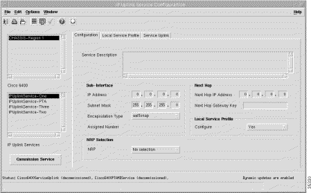
The Service Description panel allows you to enter a description for the service. Entering a Service Description is optional.
The Sub-Interface parameters define a local interface created (on the NRP) to communicate with the service network:
Next Hop IP Address--The IP Address of the next hop in the network. The SCM allows you to configure the next hop gateway IP address for the service. The SCM binds the local service profile to the next hop gateway IP address or will bind the NHG key to the next hop gateway IP address depending upon the selection made.
Next Hop Gateway Key--KEY string to bind next hop IP address to. When the Next Hop Gateway Key is not entered the Cisco 6400 SCM binds the next hop IP address to the service profile name.
Configure--Select Yes to enable the Local Service Profile tab. Select No to disable the Local Service Profile tab.
Allows you to select an NRP from the drop down list.
Click Commission Service to roll the service onto the Cisco 6400 UAC.
The Local Service Profile tab displays the parameters that you need to configured to set up the IP Uplink local service profile on the NRP-Service Selection Gateway (SSG).
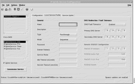
The Local Service Profile tab displays three panels: General, DNS Configuration, and Remote RADIUS Configuration.
The following General fields display:
The DNS Redirection / Fault Tolerance parameters define the DNS configuration:
The Remote RADIUS Configuration parameters are configurable when the service Type (in the General panel) is set to Proxy:
Click Commission Service to roll the service onto the Cisco 6400 UAC.
The Service Uplink tab (Figure 10-31) displays four panels:
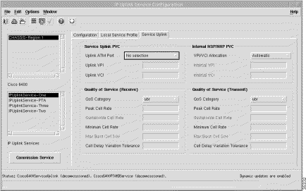
The Service Uplink PVC panel displays the physical line card and port details through which the service is accessed.
Uplink ATM Port--Allows you to select a ATM port for the uplink.
Uplink VPI--Uplink port VPI value.
Uplink VCI--Uplink port VCI value.
The Quality of Service (Receive) parameters for the egress port are set according to the marketing offering of the carrier (wholesaler) to the upstream service provider.
QoS Category--ATM Quality of Service.
 |
Note Inapplicable parameters are grayed out when a QoS Category is selected. Values are not required for all applicable parameters. For example, values can be entered for the Peak Cell Rate, Minimum Cell Rate, and Cell Delay Variation Tolerance parameters when ubr is the selected QoS Category (but values may not be required for all three parameters). |
Choose values appropriate to your selected QoS category for the following options:
The Internal NSP/NRP PVC parameters define the internal PVCs between the NSP and NRP:
The Quality of Service (Transmit) parameters for the ingress port are set according to the marketing offering of the carrier (wholesaler) to the upstream service provider.
QoS Category--ATM Quality of Service.
 |
Note Inapplicable parameters are grayed out when a QoS Category is selected. Values are not required for all applicable parameters. For example, values can be entered for the Peak Cell Rate, Minimum Cell Rate, and Cell Delay Variation Tolerance parameters when ubr is the selected QoS Category (but values may not be required for all three parameters). |
Choose values appropriate to your selected QoS category for the following options:
Click Commission Service to roll the service onto the Cisco 6400 UAC.
The RFC1483 Routing Service Configuration window (Figure 10-32) displays three tabs: Configuration, Service Details, and Service Uplink.
 |
Note See the "RFC1483 Routing Service" section for a description of this service type offered by the Cisco 6400 SCM application. |
 |
Note See the tooltips for further descriptions on each of the parameters that follow. Move the mouse pointer over the appropriate parameter and the tooltip description appears. |
The RFC1483 Routing Configuration tab displays two panels: Sub-Interface, and NRP Selection.
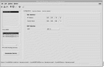
The Sub-Interface parameters define a local interface created (on the NRP) to communicate with the service network:
The NRP Selection panel allows you to select an NRP from the drop down list.
Click Commission Service to commission the service.
The Service Details tab displays two panels:
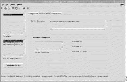
The Service Description panel allows you to enter a description for the service. Entering a Service Description is optional.
The Subscriber Connections panel displays the following information:
Click Commission Service to roll the service onto the Cisco 6400 UAC.
The Service Uplink tab (Figure 10-34) displays five panels: Internal NSP/NRP PVC, Service Uplink PVC, VC Parameters, Quality of Service (Receive), and Quality of Service (Transmit).
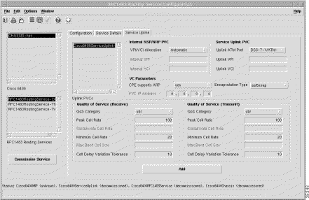
Displays a list of service uplink PVCs (this service supports multiple service uplink PVCs (select the one you wish to view/configure).
The Internal NSP/NRP PVC parameters define the internal PVCs between the NSP and NRP:
The Service Uplink PVC panel displays the physical line card and port details through which the service is accessed:
The VC Parameters panel displays the following information:
The Quality of Service (Receive) parameters for the egress port are set according to the marketing offering of the carrier (wholesaler) to the upstream service provider.
QoS Category--ATM Quality of Service.
 |
Note Inapplicable parameters are grayed out when a QoS Category is selected. Values are not required for all applicable parameters. For example, values can be entered for the Peak Cell Rate, Minimum Cell Rate, and Cell Delay Variation Tolerance parameters when ubr is the selected QoS Category (but values may not be required for all three parameters). |
Choose values appropriate to your selected QoS category for the following options:
The Quality of Service (Transmit) parameters for the ingress port are set according to the marketing offering of the carrier (wholesaler) to the upstream service provider.
QoS Category--ATM Quality of Service.
 |
Note Inapplicable parameters are grayed out when a QoS Category is selected. Values are not required for all applicable parameters. For example, values can be entered for the Peak Cell Rate, Minimum Cell Rate, and Cell Delay Variation Tolerance parameters when ubr is the selected QoS Category (but values may not be required for all three parameters). |
Choose values appropriate to your selected QoS category for the following options:
Click Commission Service to roll the service onto the Cisco 6400 UAC.
Click Add to add a new service uplink.
The Subscriber Configuration window (Figure 10-35) displays two tabs: Connections and Subscriber Details (Optional).
 |
Note See the tooltips for further descriptions on each of the parameters that follow. Move the mouse pointer over the appropriate parameter and the tooltip description appears. |
The Subscriber Configuration window displays two tabs:
The Connections tab displays a single Connection Details panel.
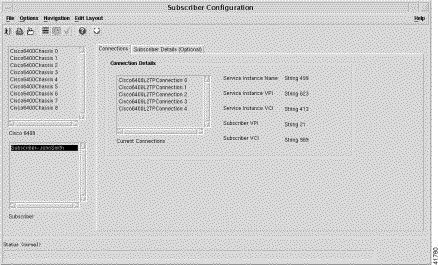
The Connection Details panel displays the following information:
The Subscriber Details (Optional) tab displays two panels: Contact Name & Address and Subscriber Name & Address.
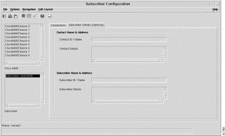
Contact ID / Name--Contact identifier or name.
Contact Details--Contact details.
Subscriber ID Name--Subscriber identifier or name.
Subscriber Details--Subscriber details.
The Service/Subscriber Connection window displays three tabs: Connection Details, Connect to Single Domain, and Connect to Multi-Domain.
The Connection Details tab displays two panels: Connection Parameters, and Internal NSP/NRP PVC.
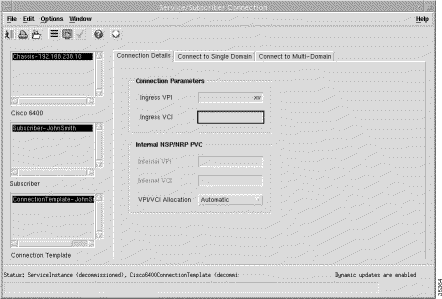
The connection parameters tab allows you to enter Ingress VPI and VCI values:
The Internal NSP/NRP PVC parameters define the internal PVCs between the NSP and NRP:
Click Connect to connect the subscriber to the service instance selected.
The Connect to Single Domain tab displays three panel: Service Instance, Subscriber Parameters, and Sub-Interface.
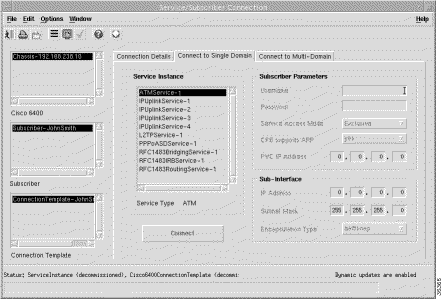
The Service Instance panel displays a list of service instances appropriate to your service type.
The subscriber parameters are:
The sub-interface parameters are:
Click Connect to connect the subscriber to the selected service instance.
The Connect to Multi-Domain tab (see Figure 10-39) displays two panels: Node Route Processor, and Subscriber Parameters.
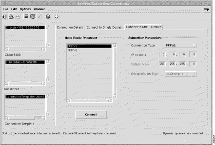
Displays a list of available NRPs.
The subscriber parameters are:
Click Connect to connect the subscriber to the selected service instance.
The Service/Subscriber Disconnection window displays a single Disconnect tab.
The Disconnect tab displays a single Connection Details panel.
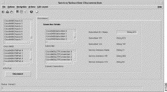
The connection parameters tab allows you to enter Ingress VPI and VCI values:
Click Disconnect to disconnect the subscriber from the service instance.
![]()
![]()
![]()
![]()
![]()
![]()
![]()
![]()
Posted: Fri Aug 4 02:05:19 PDT 2000
Copyright 1989-2000©Cisco Systems Inc.