|
|

This chapter describes the following topics:
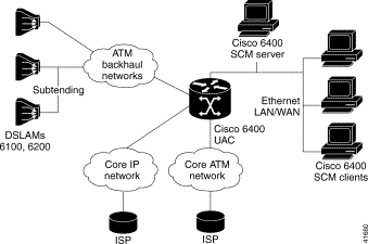
Figure 2-1 shows a typical configuration of the Cisco 6400 UAC located within the service provider's infrastructure acting as a central point of control.
Cisco EMF is an open carrier class management system, designed to integrate with third party products and proprietary operational support systems.
Many different management protocols, both standards-based and proprietary, are supported by Cisco EMF in a transparent manner. New network devices are managed instantly and new management applications can be quickly developed to meet new requirements.
Cisco EMF systems architecture provides a distributed network management solution designed to manage large-scale networks. Cisco EMF provides the performance required within the logical and physical architecture and provides user interfaces that support the need to perform mass operations to large domains within the overall network. In addition, due to the distributed nature of Cisco EMF, administration tools are provided to 'manage' the management system. Refer to the Cisco Element Management Framework User Guide for further details.
Map Viewer is the primary entry point into the Cisco 6400 SCM software. When you launch Map Viewer, a map displays corresponding to the highlighted map icon in the hierarchy pane. You can easily monitor the status of all network elements or abstractions of elements contained within the network and you can launch any additional applications available. See the "Map Viewer Window" section for further details.
Additionally, multiple Event Browsers and Map Viewer windows can run on separate client workstations, allowing a number of users to simultaneously monitor the same or distinct portions of the managed network.
All of a user's applications can run on client workstations that are remote from the server. This means that the load on the server depends only on how much data you request from the server. Therefore, the number of users is not limited by the resource footprint of the applications, all of which run on the client.
You can open multiple user sessions in Cisco EMF. Each user session has access to the tools displayed in the Launchpad. Any changes made in a user session are reflected immediately in all other user sessions.
The Cisco EMF log in window restricts user access to the Cisco 6400 SCM based on a pre-set name and password combination defined by the system administrator.
The Cisco 6400 SCM maintains a log-in record of users who access the Element Manager windows. This information is provided as ASCII text files, namely c6400Manager.audit and C6400SSManager.audit. These files are found in <CEMFROOT>/logs.
A map is a pictorial representation of related objects being managed. Define maps in a hierarchy where each node on a map has a submap. You can view different levels of complexity in the managed network by looking at high level maps or by navigating to submaps that represent lower levels of detail in the managed network.
Nodes and links on a map are pictorial icons representing managed or abstracted objects in the network. A node has an iconic representation, while a link has a vector representation. Links can only exist as a connection between two nodes.
Nodes and links can have submaps, creating a hierarchy of browsable maps. Top level maps display administrative or physical network domains; submaps display more detail until actual managed elements are represented.
Network nodes display the current alarm status of a represented object. The alarm status of an object reflects the most severe alarm currently active on an object.
A submap relays the most severe alarm status of all its nodes to the corresponding node on the parent map. The node on the parent map then displays the combined severity of its submap and the node it represents.
This means that you can view a top level map and see the overall status of the entire network. When a node on the map shows a condition or alarm, you can view successive submaps until the source of the condition or alarm appears.
The Viewer application uses the concept of "Views" to present multiple complementary methods of viewing network relationships. See the "Views" section for further details.
The toolbar at the top of each window contains icons that invoke various tools and menu options. The icons displayed in the toolbar vary depending on which window you are viewing. You can disable the toolbar so that it does not display in the window. An example of a toolbar is shown in Figure 2-2.

The tooltips option displays a brief description of each icon. This description appears when the cursor is left over the icon. Tooltips are enabled by default.
Select the Windows menu option to view a list of the windows you have open.
Throughout Cisco EMF, you can access pop-up menus from map objects, events listed in the Event Browser, and objects listed in any view. To access these pop-up menus, right click the desired object.
Throughout Cisco EMF you can select individual or multiple items from lists in the various windows. Refer to the Cisco Element Management Framework User Guide for further details on selecting from lists.
Cisco EMF uses Telecom Graphics Objects (TGO) in the Map Viewer application. TGO is a TeleManagement Forum (TMF) sponsored initiative to provide standard graphical representations for network topology maps.
TGO display additional information icons on top of the existing object icons displayed in Map Viewer. The additional information icons indicate a variety of information, for example, information on the state of the object or event status information.
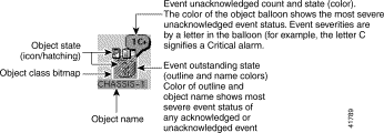
An object is a representation of a network element. For example, this could be a node, a shelf, a shelf item, or a link. Each object shown in the right window provides pictorial cues which provide information about its associated network element. The information can be structural information, for example, a network element name, or state and event information, such as "out of service."
Each object can display the following information about its associated network element:
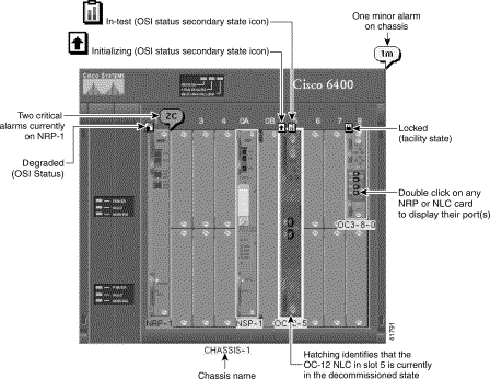
Figure 2-4 shows an example Cisco 6400 SCM chassis map displaying a few of the TGO icons that could appear.
Refer to the Cisco Element Management Framework User Guide for further information on the type of TGO objects that can appear in the Cisco 6400 SCM.
The Cisco 6400 SCM is the carrier class element manager for the Cisco 6400 UAC. The Cisco 6400 SCM "plugs into" the Cisco EMF. The Cisco 6400 SCM software adds additional windows and a back-end "Controller" process, that communicate with the Cisco 6400 UAC hardware elements (using Cisco EMF) as shown in Figure 2-5.
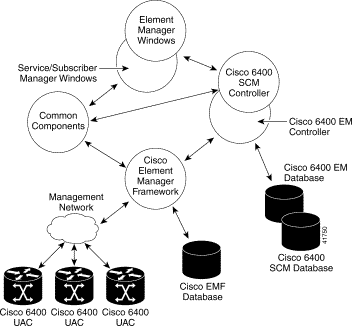
Cisco 6400 SCM application uses a number of components that are common to other Cisco Element Managers (for example, the Cisco DSL Manager and the Cisco 12000 GSR Manager). Use of the common components ensures consistent user interfaces between Cisco EMF management solutions.
You must start a Cisco EMF user session before you can launch the Cisco 6400 SCM application. Launch the Cisco 6400 SCM application from the Cisco EMF launchpad. See the "Starting the Cisco EMF and Cisco 6400 SCM Software" section for further details.
The Cisco 6400 SCM software has two distinct components: Element Management and Service Connection Management.
An Element Manager is an application that provides Fault, Configuration, Alarm, Performance, and Statistics (FCAPS) management for a particular type of network element or family of network elements.
Element managers integrate seamlessly with generic Cisco EMF applications such as maps and event browsers.
Element Management consists of FCAPS and Operations, Administration, Maintenance and Provisioning (OAM&P) features and provides a more detailed view of the underlying network elements.
See "Managing the Cisco 6400 SCM Element Manager Windows" for further details.
Cisco devices come in many different shapes and sizes but, the fundamental architecture is often similar. The device architecture can be broken down into chassis, module and interface parts that are supported by a set of MIBs and by Cisco IOS.
Analysis shows that there are common levels of basic management that you can apply at the chassis, module, and interface levels, although interfaces by their nature do have individual and unique requirements. A set of modular common components have been developed that can provide this manageability. A number of Cisco Element Managers now incorporate common components, for example, the Cisco 6260 CDM, Cisco 6400 SCM, and the Cisco 12000 GSR.
Table 2-1 displays a few of the common component windows that have been integrated, as follows:
| Common Component | Example Common Component Windows Added to the Cisco 6400 SCM |
Chassis | Chassis Configuration, and SNMP Management |
Module | Module Configuration, Module Performance, SSG Configuration, Event History, Syslog Message, IOS Image Download, and Configuration Backup/Restore |
Interface | Interface Configuration, Interface Performance, and Interface Status window |
Service Connection Management can create and configure subscribers and services and manage resultant subscriber, services connections. Performing these functions does not require an understanding of the details of the underlying network elements.For further details, see "Service/Subscriber Provisioning."
The Cisco EMF MapViewer application allows complete flexibility in viewing, building, and monitoring your network using pictorial representations of your network elements.
MapViewer is the primary entry point into the Cisco 6400 SCM. When the MapViewer application is launched, a window appears corresponding to the highlighted map icon in the hierarchy pane. You can easily monitor the status of all network elements or abstractions of elements contained within the network and you can launch any of the additional applications on the Cisco EMF Launchpad.
To view the chassis map for a selected site, follow these steps:
Step 2 Click the Viewer icon (see Figure 2-6) to launch the MapViewer application or select Map Viewer from a pop up menu when using other Cisco EMF applications. The pop up menu is accessed by right clicking a selected object. A window similar to Figure 2-6 appears.

The Map Viewer window is divided into two panels:
You can perform the following functions from Map Viewer:
The services available depends on the class of that object and is enabled or disabled according to the access of the user.
 |
Note When multiple objects are selected, only the menu options common to all of the objects are available. |
A Map Viewer window appears (similar to the example shown in Figure 2-6). The 6400 SCM Map Viewer window displays a pictorial representation of the objects in your system.
Step 3 Double click the c6400Manager view in the left hierarchy panel (see Figure 2-7). The Shelf objects deployed within your system display.
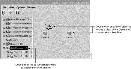
Step 4 Double click an appropriate Shelf object. The Map Viewer window displays a pictorial representation of the Cisco 6400 chassis for the selected shelf.
 |
Note The pictorial representation of the Cisco 6400 chassis (see Figure 2-8) is only available from the c6400Manager View. |

The following list describes the OSI Status and displays the secondary state icons that appear while using the Cisco 6400 SCM:


Each card in the rack has a color-coded box that identifies the card type, its position in the chassis rack, and its current alarm status.
Green is a "normal" state; orange is a major alarm; and hatching is a decommissioned (unmanaged) element. For example, in the chassis map (see Figure 2-8) OC3-8-0 identifies a OC3 node line card (OC3) in slot 8 (8) occupying the top half sub slot (0) of the slot and the green color indicates that the OC3 node line card is in its normal state.
 |
Note This naming convention is only used when subrack discovery is used. See the "Quick Start Deployment" section for further information. The names can be changed later or you can use your own naming conventions when deploying the cards manually. |
Right click any card (module) to display the menus appropriate to that card (module). For example, right clicking a NSP displays the appropriate menus for an NSP, and right clicking an NLC card displays the appropriate menus for an NLC card.
 |
Note Most of the tasks you may need to perform can be accomplished using the menus that display on the chassis map. |
Figure 2-9 shows an example of a typical menu that displays when you right click an NSP module.
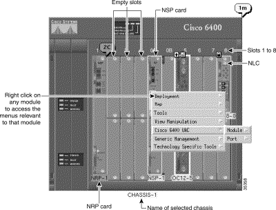
The Cisco 6400 SCM application allows NRP and NLC port objects to be accessed from the chassis view. Double click an NRP or NLC card on the Chassis map to view the port objects.
 |
Note Each NRP has a single port and each NLC has two ports. |
Figure 2-10 displays an example of the port objects that appear when you double click an NLC.

Views (see Figure 2-11) model hierarchical relationships between objects, both physical and logical. Objects are organized into different views and objects can exist in multiple views simultaneously by reference. Each object can have a number of "parents" and "children" objects. You can access Cisco 6400 SCM objects by navigating through one of the views to find the object. Each view represents a different way of containing and grouping objects.

The Cisco 6400 SCM adds additional views to the standard views supplied by the Cisco EMF during installation. The standard Cisco EMF software provides the Physical and Network views.
The Cisco 6400 SCM displays the following views:
1. Cisco6400ConnectionTemplateView is a new view added in release 2.0.x of the Cisco 6400 SCM software
2. Cisco 6400 service view (Cisco6400ServiceView) previously called serviceInstanceContainment in release 1.x of the Cisco 6400 SCM software
3. Cisco 6400 subscriber view (Cisco6400SubscriberView)--previously called subscriberContainment in release 1.x of the Cisco 6400 SCM software
4. Component managed view (added by the Common Object Model in release 2.0.x of the Cisco 6400 SCM software)
5. Network view--is a standard view added by the Cisco EMF software
6. Physical view--is a standard view added by the Cisco EMF software, this view was called physContainment in release 1.x of the Cisco 6400 SCM software. The Physical icon identifies the physical view as the only editable view
7. Manager view (c6400Manager)
8. Generic Objects view (genericObjects)
Each View is now discussed in greater detail.
A service (see Figure 2-12) exists on a Cisco 6400 chassis. A service instance has a number of dynamically created connections that are related to the service instance by this view. A connection links a subscriber to a service instance.
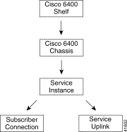
A subscriber has a number of connection objects that are related to the subscriber by this view. A connection object links a subscriber to a service instance.
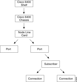
A service belongs to a specific service category and represents a service offered by a service provider (for example, xyz-gold). A service instance is a service deployed on a single Cisco 6400 SCM (for example, xyz-gold.mtn-view-1).
 |
Note You do not need to use the component managed view in the Cisco 6400 SCM. |
The Component Managed view holds all of the Cisco 6400 SCM managed objects in the network. This view shows management relationships between objects. In general, lower objects in the view are managed by higher objects.
The Network view (see Figure 2-14) represents the network devices within their relevant networks and subnets. This view is used by the Auto Discovery subsystem of Cisco EMF to calculate which devices have already been added to the system so that it does not try to discover the same device multiple times. The Network view is a standard view within Cisco EMF software.

The Network view displays all IP devices under their parent network. This view provides a logical layout of the network structure. It does not provide topology information.
 |
Note You are not likely to need to use this view. |
Refer to the Cisco Element Management Framework User Guide for further information.
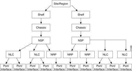
The Physical view (see Figure 2-15) reflects the physical relationship of objects within the whole network and provides relevant information to draw maps.
 |
Note When more than one Element Manager is installed, objects appear in the physical view for the other EMs. Each NRP always has a single port in the Cisco 6400 SCM software and a NLC typically has two ports. Multiple NRPs and NLCs can be present in a chassis but only a single NSP within a chassis. |
The Physical view is a standard view within Cisco EMF software. Refer to the Cisco Element Management Framework User Guide for further information.
 |
Note You can view Cisco 6400 ATM ports from the chassis map using the C6400 Manager view. See the "Accessing Port Objects From Maps" section for further details. |
The Cisco 6400 manager view (see Figure 2-16) reflects the relationship between SCM objects and displays a representation of the chassis front panel contents.
The Cisco 6400 manager view is the main view for Cisco 6400 UAC management using the Cisco 6400 SCM application and the one recommended for day to day management.
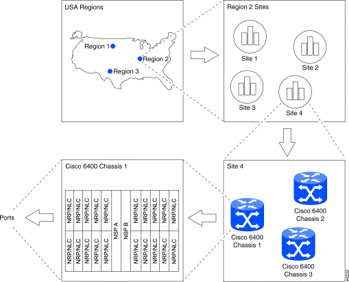
The Cisco 6400 Manager view is added by the Cisco 6400 SCM software.
The Generic Objects view is a standard view within Cisco EMF software. Refer to the Cisco Element Management Framework User Guide for further information.
The Cisco 6400 UAC offers Layer 2 and Layer 3 services, such as tunneling and bridging. The Cisco 6400 SCM application simplifies provisioning of these services, as well as providing "FCAPS" element management of the Cisco 6400 UAC.
The service names have been updated for Release 2.x of the Cisco 6400 SCM application. Table 2-2 details the services supported by the Cisco 6400 SCM application in Release 2.x (and the previous names of these services as they appeared in Release 1.x).
| SCM Release 2.x | Previous Name in SCM Release 1.x |
Pure ATM switching service | Pure ATM switching service |
PPPoA-Single Domain (SD) | PPP-IP |
L2TP | PPP-L2TP |
RFC1483 Routing | RFC1483 |
RFC1483 Bridging | Bridged-bridged |
RFC1483 Integrated Routing and Bridging (IRB) | Bridged-routed |
IP Uplink (supporting PTA-MD and Route Bridge Encapsulation (RBE)) | PPP Termination Aggregation over Multiple Domains (PTA-MD) and Route Bridge Encapsulation (RBE) |
The following sections describe each of the services available in the more detail.
Figure 2-17 shows an instance of a service that belongs to the Pure ATM Switching Service category, that exists on the NSP and will connect two ATM ports (subscriber and service) on the NSP together.
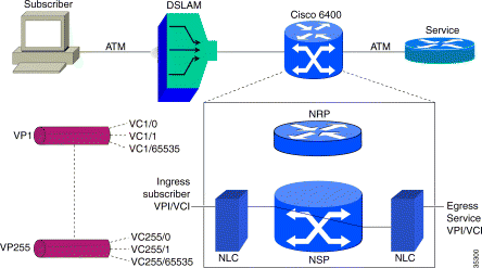
The pure ATM switching service (left to right) connects subscribers using. For example, DSLAMs in the Cisco end-to-end DSL architecture through an ATM network or perhaps directly into the Cisco 6400 UAC. From there, the connection is made to the service provider, where it terminates (typically via a router).
In the Cisco 6400 UAC, for pure ATM switching service, NRPs are not actually used (that is, no configuration takes place on the NRP for this service), and therefore the Cisco 6400 UAC is functioning as an ATM switch. You therefore configure the ATM service, select the subscriber or incoming VPI/VCI, select the service VPI/VCI and connect it together. The subscriber is connected to the service provider using a pure ATM network without the need for routing functions. Only the egress (outgoing) ATM port VPI/VCI parameters require to be set up, making the ATM service the simplest Cisco 6400 SCM service to set up.
 |
Note Only one subscriber can be connected to an ATM cross-connect service. |
See the "Service/Subscriber Provisioning" section for further details on each of the Cisco 6400 SCM services.
 |
Note Additional routing configuration information may be required to the NRP using Cisco IOS commands before configuring the PPPoA-SD service. Refer to the "Cisco 6400 UAC Command Reference Guide" for further details. |
Figure 2-18 shows an instance of a service that belongs to the PPPoA-SD Service category that exists on the NRP, where the Cisco 6400 is required to terminate PPP connections using the pre-defined IP Addresses, Authentication protocol and other attributes as defined in the Virtual Template for this service. This Virtual Template must be referenced by the Permanent Virtual Circuit (PVC), that is part of the connection.
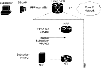
The subscriber connects to the DSLAM (the protocol between DSLAM and the Cisco 6400 UAC is PPP over ATM) and this is routed via the Cisco 6400 UAC onto a core IP network. The PPPoA-SD local termination service will enable you to configure the Cisco 6400 UAC from the incoming subscriber VPI/VCI through to the router (the NRP). From this point the routing is the responsibility of the end operator.
Refer to the Cisco IOS documentation supplied with your Cisco 6400 UAC system for details of how to set up the uplink.
See the "Service/Subscriber Provisioning" section for further details on each of the Cisco 6400 SCM services.
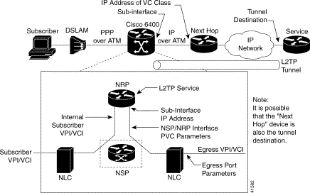
This service involves connecting the subscriber to an upstream service provider (for example, an Internet service provider [ISP]) through an L2TP tunnel.
The subscriber traffic is switched by the NSP onto the selected NRP and the tunnels set up between the uplink on the Cisco 6400 UAC through the IP network to the service provider. The network architecture may not precisely match that shown in Figure 2-19. The exact network architecture is dependant on the service provider requirements. There are a number of parameters required to set up the L2TP service and there are a number of network elements you must configure.
See the "Service/Subscriber Provisioning" section for further details on each of the Cisco 6400 SCM services.
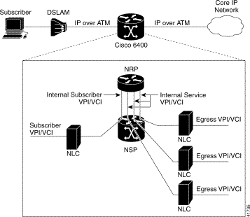
Routing service compliant with RFC1483 (see Figure 2-20) connects subscribers to (potentially) multipoint service uplink PVCs (residing within an uplink subinterface), using AAL5 SNAP encapsulation to carry IP traffic over ATM. The IP traffic is routed by the NRP as required. This service is currently the only SCM-supported service that permits multiple uplink PVCs.
See the "Service/Subscriber Provisioning" section for further details on each of the Cisco 6400 SCM services.
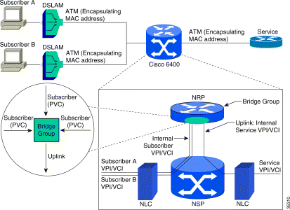
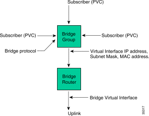
A bridge lets you connect multiple subscribers into a virtual LAN. Subscriber policies for the bridge group can be configured and applied within the Cisco 6400 SCM to control the manner in which the bridge traffic passes between the subscribers and the uplink. A bridge group is displayed in the NRP in Figure 2-21. The bridge group is responsible for bridging traffic between the subscribers (who are members of the bridge group) and the uplink.
See the "Service/Subscriber Provisioning" section for further details on each of the Cisco 6400 SCM services.
The RFC1483 IRB service (see Figure 2-22) is a variant on the RFC1483 Bridging service (see Figure 2-21).
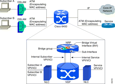
Routing can occur within the NRP as well as the bridge. Multiple subscribers connected to a bridge group, virtual LAN capability, various types of switching, either on to service providers or on to core IP networks via the NRP.
See the "Service/Subscriber Provisioning" section for further details on each of the Cisco 6400 SCM services.
Figure 2-23 illustrates a conceptual view of the bridge group and its associated bridge virtual interface. The bridge virtual interface receives the traffic passed onto it from the bridge group and routes this to the associated uplink.
See the "Service/Subscriber Provisioning" section for further details on each of the Cisco 6400 SCM services.
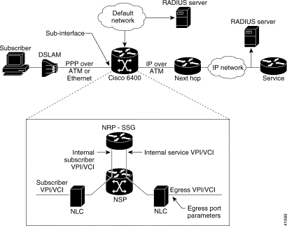
The IP Uplink service (see Figure 2-24) provides an uplink from the NRP to remote services. Configuring the IP Uplink service consist of two components:
 |
Note The IP Uplink service is supported on the NRP at Cisco IOS version 12.0(3)DB and later. |
See the "Service/Subscriber Provisioning" section for further details on each of the Cisco 6400 SCM services.
 |
Note Proxy authentication is applicable when the Configure option in the Local Service Profile panel on the IP Uplink Service Profile Configuration Window (Configuration tab) is set to Yes. See the "Service/Subscriber Provisioning" section for further details. |
See the "IP Uplink (for PTA-MD and RBE Subscribers) Service Profile Configuration Window" section for details on each of the parameters displayed on Figure 2-24.
![]()
![]()
![]()
![]()
![]()
![]()
![]()
![]()
Posted: Thu Aug 10 06:31:58 PDT 2000
Copyright 1989-2000©Cisco Systems Inc.