|
|

This chapter describes embedded software utility functions and contains the following sections:
The EMS database backup utility allows you to back up the existing configuration of a node to a TFTP server. After the database has been backed up, you can restore the node configuration, if needed. The database restore procedure is described in the "Restoring a Database".
Before beginning the database backup, complete the following tasks:
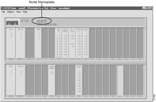
Step 2 Double-click the node nameplate to launch the NE provision window. (See Figure 14-2.)
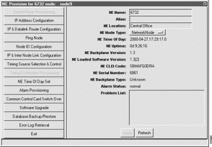
Step 3 Select Database Backup from the function bar. (See Figure 14-3.)

Step 4 Complete the following fields to begin the database backup procedure:
Step 5 Click Apply to save the backup configuration.
Step 6 Click Backup to begin the database backup.
The following sections describe the Stratum 3 or Stratum 4 MCC embedded software upgrade procedure for the Cisco 6732:
 |
Note Reset procedures are also covered in the "Node Critical Commands". |
 |
Caution For a successful upgrade, follow all procedures, and all steps, in sequence. |
 |
Caution If for any reason EMS is unable to complete the embedded software upgrade, do not reset the MCC card. You must restart the embedded software upgrade process. Resetting the MCC with a partial software image corrupts the MCC. If there is an error, an error message displays in the Software Upgrade Status field, or at the bottom of the NE provision window, as well as in the problem list of the MCC card (if the card is functional). |
Before beginning the embedded software upgrade, complete the following tasks:
 |
Caution Be certain you are not upgrading to embedded software Version 1.4. Embedded software Version 1.4 only operates with the Cisco IAD1101. Check with your system administrator, if necessary. |
 |
Caution When upgrading multiple nodes in a network, always start from the far end of the network, one node at a time. In a typical network, a number of remote nodes (subscriber nodes) are connected to a central office terminal (COT) node. If the upgrade of COT is mishandled, the entire network can be lost. Upgrade tests and sample enhancements should be made at the edge node. If the upgrade tests fail on the edge nodes, do not attempt to upgrade the COT node. |
Step 2 Click Common Control Card Switch Over in the function bar to view the switchover window. (See Figure 14-4.)

Step 3 Look at the Active MCC field. EMS identifies the active MCC:
Step 4 Identify the standby MCC. The screen does not show the standby MCC. The MCC that is not active is called the standby MCC. For example, if MCC-A is active, then MCC-B is the standby MCC.
Step 5 Click Exit to return to NodeView.
Step 2 Set the Admin Status field to OutOfService.
Step 3 Click Apply to place the MCC card out of service.
Step 4 Click Exit to return to Cisco 6700 NodeView.
Step 2 Click Software Upgrade in the function bar to view the software upgrade window. (See Figure 14-5.)

Step 3 In the Software Image Host IP Address field, enter the IP address of the TFTP server.
Step 4 In the Software Image File Name field, enter SwLoad.iad.
Step 5 From the Card Side drop-down menu, select the shelf (A = top shelf, B = bottom shelf) containing the standby MCC card (in this example, the bottom shelf).
Step 6 Click Apply to confirm the host IP address and path to the image filename.
Step 7 Click Upgrade. The backup LED on the standby MCC flashes as the embedded software image downloads into the card's Flash memory.
Step 8 Observe the progress bar. (See Figure 14-6.) When the Software Upgrade Status field in the Software Upgrade Window reads: "passed", the upgrade is complete.
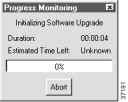
Step 9 Click Exit to return to Cisco 6700 NodeView.
Step 10 Reset the Standby MCC card (see the next procedure, "Resetting the Standby MCC Card").
 |
Caution Do not power down the NE or remove the MCC during an MCC reset. The MCC must finish loading the system software before the MCC can be safely powered down, removed, reset, or reprovisioned. |
 |
Note Performing an MCC reset erases the internal clock on the NE. To set the time of day on the NE, see the "Provision NE Clock" section of "Initial Node Provisioning." |
Step 2 Enter the node critical commands password. The node critical commands window opens, displaying the database restore function. (See Figure 14-7.) If necessary, contact your EMS administrator to obtain the correct node critical commands password.
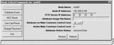
Step 3 Click MCC Reset in the function bar to open the MCC reset window. (See Figure 14-8.)
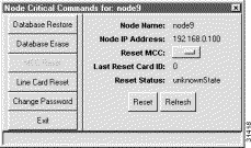
Step 4 In the Reset MCC field, select the standby MCC (A or B)
Step 5 Click the Reset button and respond Yes to the prompt. Allow at least 45 seconds for the MCC to reset and reload the system software.
Step 6 Click Refresh. The Reset Status field should read "reset".
Step 7 Click Exit to return to NetView.
Step 2 Confirm that the version number in the Software Version field is correct.

Step 2 Set the Admin Status field to InService (you can safely dismiss the warning message).
Step 3 Click Apply to place the card in service.
Step 4 Click Exit to return to NodeView.
Step 2 Click Software Upgrade in the function bar to view the software upgrade window.
(See Figure 14-5.)
Step 3 In the Software Image Host IP Address field, enter the IP address of the TFTP server.
Step 4 In the Software Image File Name field, enter SwLoad.fbx.
Step 5 From the Card Side drop-down menu, select the shelf (A = top shelf, B = bottom shelf) containing the active MCC card.
Step 6 From the Target Card drop-down menu, select the active MCC card.
Step 7 Click Apply to confirm the host IP address and path to the image filename.
Step 8 Click Upgrade to download the embedded software image into the Flash memory of the MCC card. EMS displays a progress bar. (See Figure 14-6.) Wait until the software upgrade is complete and the Software Upgrade Status field reads: "passed".
Step 9 Click Exit to return to NodeView.
 |
Note The MCC switchover (described in the next procedure) automatically resets the active MCC. You do not have to perform an independent reset. |
 |
Note Performing an MCC reset erases the internal clock on the NE. To set the time of day on the NE, see "Setting the NE Clock". |
Step 2 Click Common Control Card Switch Over in the function bar. (See Figure 14-10.)

Step 3 Click Switch to switch control from the active MCC to the standby MCC.
Step 4 Respond Yes to the confirmation prompt. EMS switches traffic to the standby MCC.
Step 5 Click Exit to return to NodeView.
 |
Note The line card reset procedure applies to all Cisco 6700 series platforms. BPS-HP and AMM service modules do not need to be reset. |
 |
Caution The line card reset procedure reboots the line interface modules and effectively takes them out of service. Any traffic carried on the line cards is lost or dropped. To eliminate or reduce the potential for interrupted subscriber service, plan and coordinate this activity carefully. |
Step 2 Enter the node critical commands password. The node critical commands window opens, displaying the database restore function. (See Figure 14-7.) If necessary, contact your EMS administrator to obtain the correct node critical commands password.
Step 3 Click Line Card Reset in the function bar to open the line card reset window. (See Figure 14-11.)

Step 4 From the Equipped Cards list, either select a line card to be reset, then in the Reset field, choose Selected, or, in the Reset field, choose All.
Step 5 Click Apply to reset either the selected line card, or all line cards.
Step 6 Repeat Step 4 and Step 5 for each card that you want to reset.
The following section describes the MCC INT embedded software upgrade procedure for the Cisco 6705:
 |
Note The Cisco 6705 has only one MCC card, identified as "MCC INT". |
 |
Note Reset procedures are also covered in the "Node Critical Commands". |
 |
Caution For a successful upgrade, follow all procedures, and all steps, in sequence. |
 |
Caution If for any reason EMS is unable to complete the embedded software upgrade, do not reset the MCC card. You must restart the embedded software upgrade process. Resetting the MCC with a partial software image corrupts the MCC. If there is an error, an error message displays in the Software Upgrade Status field, or at the bottom of the NE provision window, as well as in the problem list of the MCC card (if the card is functional). |
Before beginning the embedded software upgrade, complete the following tasks:
 |
Caution Be certain you are not upgrading to embedded software Version 1.4. Embedded software Version 1.4 only operates with the Cisco IAD1101. Check with your system administrator, if necessary. |
 |
Note When upgrading multiple nodes in a network, always start from the far end of the network, one node at a time. In a typical network, a number of remote nodes (subscriber nodes) are connected to a central office terminal (COT) node. If the upgrade of COT is mishandled, the entire network can be lost. Upgrade tests and sample enhancements should be made at the edge node. If the upgrade tests fail on the edge nodes, do not attempt to upgrade the COT node. |
Step 2 Select Software Upgrade from the function bar to view the software upgrade window. (See Figure 14-12.)

Step 3 In the Software Image Host IP Address field, enter the IP address of the TFTP server.
Step 4 In the Software Image File Name field, enter SwLoad.fbx.
Step 5 Click Apply to confirm the host IP address and path to the image filename.
Step 6 Click Upgrade to download the embedded software image into the Flash memory of the MCC card. EMS displays a progress bar. (See Figure 14-6.) Wait until the software upgrade is complete and the Software Upgrade Status field reads: "passed."
The MCC INT card must be reset before the new embedded software becomes active.
 |
Caution Resetting the MCC INT card resets all line cards in the Cisco 6705, momentarily placing the line cards out of service. Any traffic carried on the line cards is lost or dropped. To eliminate or reduce the potential for interrupted subscriber service, plan and coordinate this activity carefully. |
 |
Caution Do not power down the NE or remove the MCC during an MCC reset. The MCC must finish loading the system software before the MCC can be safely powered down, removed, reset, or reprovisioned. |
 |
Note Performing an MCC reset erases the internal clock on the NE. To set the time of day on the NE, see "Setting the NE Clock". |
There are two ways to reset the MCC card: physically, or through the software.
Step 2 Gently slide the MCC card away from the NE chassis backplane.
Step 3 Reinstall the MCC card by carefully sliding it forward until the lever touches the front of the chassis.
Step 4 Secure the MCC card by pressing the lever down. See the Cisco 6705 Hardware Installation Guide for handling procedures. Allow at least 45 seconds for the MCC to reset and reload the system software.
Step 2 Enter the node critical commands password. The node critical commands window opens, displaying the database restore function. (See Figure 14-13.) If necessary, contact your EMS administrator to obtain the correct node critical commands password.
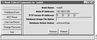
Step 3 Click MCC Reset in the function bar to view the MCC Reset window. (See Figure 14-14.)

Step 4 Click the Reset button and respond Yes to the prompt. Allow at least 45 seconds for the MCC to reset and reload the system software.
Step 5 Click Exit in the function bar to return to Cisco 6700 NetView.
The following section describes the software upgrade procedure for the Cisco IAD1101, and includes the following sections:
 |
Note The Cisco IAD1101 has an internal MCC card. The MCC card is always the target of the upgrade procedure. |
 |
Caution The software upgrade procedure requires a reset of the Cisco IAD1101 internal MCC card. This causes all lines and cards to reset, momentarily placing the lines out of service. Any traffic carried on the line cards is lost or dropped. To eliminate or reduce the potential for interrupted subscriber service, plan and coordinate this activity carefully. |
 |
Caution For a successful upgrade, follow all procedures, and all steps, in sequence. |
 |
Caution If for any reason EMS is unable to complete the embedded software upgrade, do not reset the MCC card. You must restart the embedded software upgrade process. Resetting the MCC with a partial software image corrupts the MCC. If there is an error, an error message displays in the Software Upgrade Status field, or at the bottom of the NE provision window, as well as in the problem list of the MCC card (if the card is functional). |
Before beginning the embedded software upgrade, complete the following tasks:
 |
Caution Be certain you are upgrading to embedded software Version 1.4. Check with your system administrator, if necessary. |
 |
Note When upgrading multiple nodes in a network, always start from the far end of the network, one node at a time. In a typical network, a number of remote nodes (subscriber nodes) are connected to a central office terminal (COT) node. If the upgrade of COT is mishandled, the entire network can be lost. Upgrade tests and sample enhancements should be made at the edge node. If the upgrade tests fail on the edge nodes, do not attempt to upgrade the COT node. |
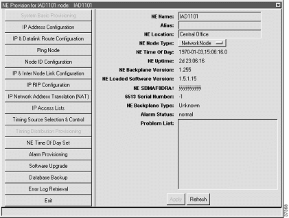
Step 2 Select Software Upgrade from the function bar to view the software upgrade window. (See Figure 14-16.)
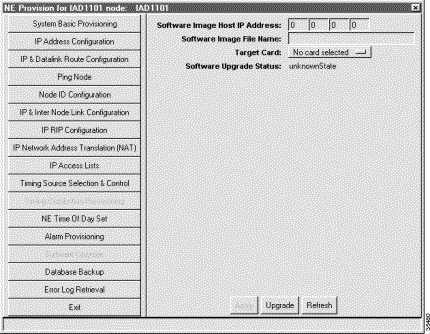
Step 3 In the Software Image Host IP Address field, enter the IP address of the TFTP server.
Step 4 In the Software Image File Name field, enter SwLoad.iad.
Step 5 Set the Target Card field to MCC.
Step 6 Click Apply to confirm the host IP address and path to the image filename.
Step 7 Click Upgrade to download the embedded software image into the Flash memory of the MCC card. EMS displays a progress bar. (See Figure 14-6.) Wait until the software upgrade is complete and the Software Upgrade Status field reads: "passed."
Step 8 Respond to the reboot prompt by dismissing it and resetting the internal MCC card (see "Resetting the Internal MCC Card").
 |
Caution The Cisco IAD1101 internal MCC card must be reset before the new embedded software becomes active. This momentarily places the lines out of service. Any traffic being carried on an installed line card is lost or dropped. |
 |
Caution Do not power down the NE or remove the MCC during an MCC reset. The MCC must finish loading the system software before the MCC can be safely powered down, removed, reset, or reprovisioned. |
 |
Note Performing an MCC reset erases the internal clock on the NE. To set the time of day on the NE, see the "Provision NE Clock" section of "Initial Node Provisioning." |
Step 2 Enter the node critical commands password. The node critical commands window opens, displaying the database restore function. (See Figure 14-13.) If necessary, contact your EMS administrator to obtain the correct node critical commands password.
Step 3 Select MCC Reset in the function bar on the left side of the window to open the MCC Reset window. (See Figure 14-14.)
Step 4 Click the Reset button and respond Yes to the prompt. Allow at least 45 seconds for the MCC to reset and reload the system software.
Step 5 Click Exit.
Step 6 From Cisco 6700 NodeView Objects menu, select Plugin Card Details. EMS displays the Plugin Card Detail Info Display window. (See Figure 14-17.)

Step 7 In the Card ID field, select MCC and verify the software version number.
This section describes the embedded software utilities that are launched from the node critical commands window:
 |
Caution These commands affect service; any user traffic passing through the node will be dropped. To eliminate or reduce the potential for interrupted subscriber service, plan and coordinate these activities carefully. |
To launch the node critical commands window, complete the following steps:
Step 2 Enter the node critical commands password. The node critical commands window opens, displaying the database restore function.
 |
Note Your EMS workstation requires a special password file to launch the node critical commands window. If EMS cannot locate the password file, you cannot launch the node critical commands window. Contact your EMS administrator to obtain the password file. |
Use the database restore function to restore a backedup database to an MCC on the Cisco 6732, Cisco 6705, or Cisco IAD1101. See the "Backing Up the System Database" for the database backup procedure.
Step 2 Enter the node critical commands password. The node critical commands window opens, displaying the database restore function. See Figure 14-18.)

Step 3 Complete the following fields:
Step 4 Click Restore to upload the database file from the TFTP server to the selected MCC.
Step 2 Enter the node critical commands password. The node critical commands window opens, displaying the database restore function. (See Figure 14-19.)
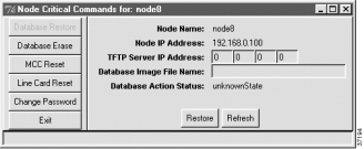
Step 3 Complete the following fields:
Step 4 Click Restore to upload the database file from the TFTP server to the selected MCC.
 |
Caution Erasing the database removes all card and line provisioning, including cross connects and inter node connections. |
Step 2 Click Database Erase in the function bar to open the database erase window. (See Figure 14-20.)
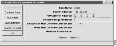
Step 3 Select the MCC to be erased in the Database on Main Common Control Card field.
Step 4 Click Erase.
Step 2 Click Database Erase in the function bar to open the database erase window. (See Figure 14-21.)

Step 3 Click Erase.
The MCC reset function resets the main control card (MCC) and reloads the embedded software.
 |
Caution Resetting the MCC causes all lines and cards in the NE to be reset as well, momentarily placing the line cards out of service. Any traffic being carried on the line cards is lost or dropped. To eliminate or reduce the potential for interrupted subscriber service, plan and coordinate this activity carefully. |
 |
Caution Do not power down the NE or remove the MCC during an MCC reset. The MCC must finish loading the system software before the MCC can be safely powered down, removed, reset, or reprovisioned. |
Refer to "Resetting the Standby MCC Card".
Refer to "Resetting the MCC INT Card".
Refer to "Resetting the Internal MCC Card".
 |
Note Performing an MCC reset erases the internal clock on the NE. To set the time of day on the NE, see the "Provision NE Clock" section of "Initial Node Provisioning." |
The line card reset function resets all selected cards in the NE.
 |
Caution The line card reset procedure reboots the selected line cards and effectively takes them out of service. Any traffic carried on the line cards is lost or dropped. To eliminate or reduce the potential for interrupted subscriber service, plan and coordinate this activity carefully. |
To reset line cards in a Cisco 6700 series NE, refer to the "Resetting the Line Cards".
You can use the change password function to change the node critical commands password. This password is used to launch the node critical commands window. (See Figure 14-22.)
 |
Note The node critical commands password is not the password used to log in to EMS. To change the EMS login password for a particular user, see "Provisioning EMS User Security". |
Step 2 Click Change Password on the function bar to open the change password window. (See Figure 14-22.)
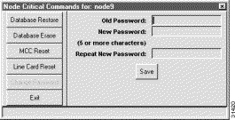
Step 3 Complete the following fields to change the node critical commands password:
Step 4 Click Save.
![]()
![]()
![]()
![]()
![]()
![]()
![]()
![]()
Posted: Mon Feb 5 13:07:14 PST 2001
All contents are Copyright © 1992--2001 Cisco Systems, Inc. All rights reserved.
Important Notices and Privacy Statement.