|
|

This chapter describes management utilities available in EMS and includes the following sections:
EMS offers three levels of security for EMS user accounts (see Table 15-1):
| Security Level | Permitted EMS Operations |
|---|---|
1 | Displays the network topology and node configurations (read only). |
2 | Displays the network topology (read only), and changes the node configurations (read/write). |
3 | Changes the network topology and node configurations (read/write), manages EMS user accounts, and provisions EMS alarms. |
EMS users with level 3 security can create, delete, and modify user accounts from EMS.
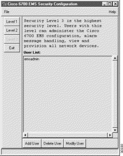
Step 2 Click the buttons labeled Level 1, Level 2, and Level 3 to view user lists for each level of EMS security. Figure 15-1 shows the Level 3 button is grayed out; this indicates that only level 3 user accounts are displayed.
Step 3 Click the following buttons to configure EMS user accounts:
The EMS inactivity timer tracks the amount of time that a particular NodeView remains open. When the inactivity timer expires, EMS displays a dialog box asking if Cisco 6700 NodeView should be kept active. (See Figure 15-2.)
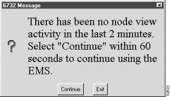
Click Continue to close the dialog box and continue working in NodeView, or click Exit to close NodeView. If no selection is made within 60 seconds, EMS closes Cisco 6700 NodeView. The timer is set to 60 minutes by default.

Step 2 Set the timer length in minutes and click Apply.
Step 3 To disable the inactivity timer, set the timer value to 0.
 |
Note The EMS inactivity timer does not apply to node critical commands. |
The EMS node search utility lets you locate a previously created node by entering the node name or IP address of the node.

Step 2 Enter either the node name or node IP address in the node search window.
Step 3 Click Search.
EMS searches all subnets and end node lists for the specified node. If a matching node is found, the node name and node ID displays in the text window.
Use the ping node utility to test network connectivity between the NE and another network element (such as a Cisco 6700 series NE or a router).

Step 2 Set the following parameters:
Step 3 Click Ping to ping the node. The results of the attempted ping are displayed in the Results list.
Step 2 Select Node Provision Management from the popup menu. EMS launches the node provision management display window. Items that display in the node provision category list vary, depending on how you provisioned the NE. (See Figure 15-6.)
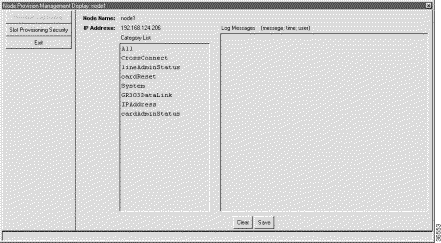
Common node provision categories are:
Step 3 Select a category by clicking it in the Category List box. EMS displays specific types of system information for the selected category.
The EMS slot provisioning security function allows selected slots in the NE to be protected from further provisioning changes. Protected slots, including the lines and cards in the protected slots, cannot be changed or modified.
 |
Note Only level 3 users can provision slot security. Level 1 and level 2 users can view existing security settings, but they cannot add, modify, or delete slot security settings. |
Step 2 Click the Slot Provisioning Security tab from the function bar. EMS displays the slot provisioning security window. (See Figure 15-7.)
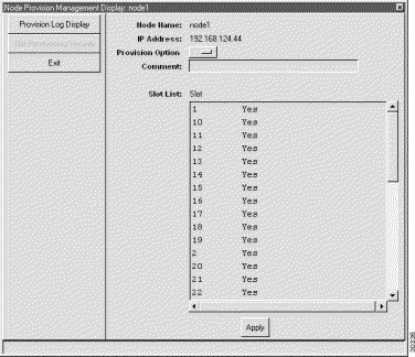
Step 3 In the Slot List window, click the slots to be provisioned.
Step 4 Set the Provision Option to Yes (allow slot provisioning) or No (disallow slot provisioning).
Step 5 Optionally, you can enter a Comment which displays next to the affected slots in the slot list.
Step 6 Click Apply to provision the slots.
The EMS schedule editor lets you schedule software utilities such as database backups and software upgrades.
 |
Note Only level 3 users can create, modify, or delete scheduled activities. Level 1 and level 2 users can view existing schedule settings, but they cannot make changes. |
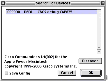
Step 2 Click Start to activate the schedule daemon. The schedule daemon must be activated for scheduled activities to take place.
Step 3 Click Stop to shut down the schedule daemon.
The schedule editor provides a configurable procedure timeout, allowing EMS to set a maximum time for database backup and software upgrade procedures.
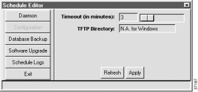
Step 2 Enter the desired timeout length in minutes in the Timeout (in minutes) field.
 |
Note If the scheduled procedure takes longer than the timeout length, EMS disconnects from the active node. The procedure continues to run, but EMS does not display status updates. |
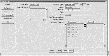
Step 2 Set the following parameters:
Step 3 Click Submit.
 |
Note EMS displays the IP addresses of all nodes in the active subnet. If the node you wish to back up does not appear in the list, return to NetView and select the proper subnet, then return to the schedule editor. |
From the Schedule Editor, click Software Upgrade in the function bar. EMS launches the software upgrade scheduler window. (See Figure 15-11.)
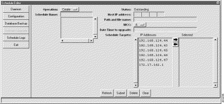
Step 2 Click Submit to complete the new schedule.
 |
Note EMS displays the IP addresses of all nodes in the active subnet. If the node you wish to upgrade does not appear in the list, return to NetView and select the proper subnet, then return to the schedule editor. |
The Schedule Log displays a detailed log of all scheduled activities.

Step 2 Select a schedule type to view. Choose either Software Upgrade or Database Backup from the Schedule Type drop-down menu.
Step 3 Click either Save Overview to create a file containing the overview information (top list), or click Save Detailed to create a file containing detailed log information (bottom list).
![]()
![]()
![]()
![]()
![]()
![]()
![]()
![]()
Posted: Mon Feb 5 13:11:25 PST 2001
All contents are Copyright © 1992--2001 Cisco Systems, Inc. All rights reserved.
Important Notices and Privacy Statement.