|
|

This chapter describes ATM provisioning procedures for the Cisco 6705 and Cisco 6732, and includes the following sections:
You can provision ATM virtual paths (VPs) and virtual channels (VCs) on the following linecards on the Cisco 6705 or Cisco 6732 for use with internal and external ATM connections:
Before provisioning a line, be sure the card and line are in service. For procedures on placing a card in service, see "About Placing Cards In Service". For procedures on placing a line in service, see the "About Line Provisioning" section.
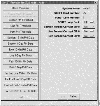
Step 2 Set the Physical Layer Admin Status to inService.
Step 3 Leave all other parameters at their default values.
Step 4 Click Apply to provision the line.
Step 5 Repeat this procedure to provision other lines on the line card.
Each line must be provisioned with at least one virtual path (VP) and one virtual channel (VC) before ATM traffic can be accommodated.
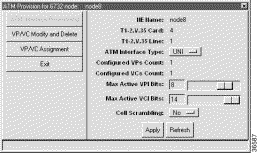
Step 2 Set the following ATM parameters:
Step 3 Click VP/VC Assignment on the function bar. EMS launches ATM Provisioning Window view that is used to assign VP/VCs. (See Figure 13-3.)
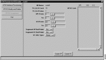
Step 4 Set the following ATM parameters:
Step 5 Click Create VP to provision the VPs. The newly-created VPs appear in the VP/VC List at the right side of the window.
Step 6 Click Create VC to provision the VCs. The newly-created VCs also appear in the VP/VC List.
Step 2 Select VP/VC Modify and Delete in the function bar. EMS displays a list of VPs and VCs provisioned on the line. (See Figure 13-4.)

Step 3 In the VP/VC List at the right side of the window, highlight the VPs and VCs you intend to delete.
Step 4 Click Delete. EMS removes the highlighted VPs and VCs from the list.
After a line had been provisioned with a VP and VC, you can create an ATM cross connect to another line in the NE chassis.
To create an ATM cross connect, complete the following steps starting in Cisco 6700 NodeView:
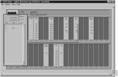
Step 2 Highlight the VP/VC to be cross connected. EMS displays the VP/VC number in the Selected VPI and Selected VCI boxes at the top of the list. (See Figure 13-6.)
Step 3 Click the Selected VCI text box, and drag the cursor to the desired facility.
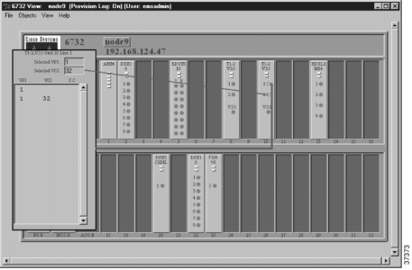
Step 4 After the visual cross connect is drawn, EMS launches the ATM Cross Connect Provisioning window. (See Figure 13-7.)
The VP/VC list on the left shows all VP/VCs for the source (originating) line, and the VP/VC list on the right shows all VP/VCs for the destination line.

Step 5 Highlight the source VP/VC to be cross connected in the left VP/VC List.
Step 6 Highlight the destination VP/VC in the right VP/VC List. You must select at least one VP/VC on each line. (If you have multiple VCs in the list, you can select a range of VCs.)
Step 7 Click Create to provision the ATM cross connection. EMS confirms the cross connect creation by displaying the letter "y" in the "CC" column, next to the connected VP/VCs. (See Figure 13-8.)

There are several ways to delete an ATM cross connect:
Step 2 Click ATM Cross Connect Provisioning on the function bar.
Step 3 In the window that appears (see Figure 13-9), select the row with a "y" in the C.C. column.

Step 4 Click Delete and respond to the prompt. The "y" disappears from the C.C. column.
To delete ATM cross connects, complete the following steps starting in Cisco 6700 NodeView:
Step 2 Select a line in the list that has a confirmed VP/VC cross connect (look for the "y"). A graphic line appears representing the cross connect. (See Figure 13-6.)
Step 3 Double-click the graphic line. EMS launches the ATM cross connect window
Step 4 In the VP/VC List, highlight the VP/VCs to be deleted.
Step 5 Click Delete. EMS removes the deleted cross connects from the VP/VC list display and removes the "y" from C.C. column on the list.
Step 2 Select End ATM Cross Connect Display from the popup menu. EMS closes the cross connect display.
ATM lists show VP/VC assignments and ATM cross connects.
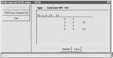
Step 2 Select ATM Cross Connect List from the function bar. EMS launches the ATM cross connect list. (See Figure 13-11.)

Step 3 Click Exit to return to Cisco 6700 NodeView.
Step 2 Verify that the module is correctly installed in the chassis.
Step 3 Check to see that the TX and RX cables are properly connected. (See "Installing EMS".)
Step 4 Check to see that both the module and line are set to InService. For procedures on placing a card in service, see "About Placing Cards In Service". For procedures on placing a line in service, see the "About Line Provisioning" section.
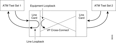
Step 5 Verify that a signal is being received by testing the line with a line loopback, then testing the cross-connect with an equipment loopback (see Figure 13-12). Check to see that the near-end and far-end modules have the same provisioning in regards to:
Step 6 Verify that you have put up a cross-connect. (See Figure 13-6.) You need a VP or a VP/VC on each module in order to cross-connect successfully.
Step 7 Be sure you have provisioned the correct cross-connect VP/VC values. For example, if you have a VP 6/VC 100 coming into a cross-connect that is provisioned as VP 20/ VC 12, the system will not pass this data through. The system only recognizes the VP/VCs it is provisioned for.
Step 8 Swap out the module, if required, and repeat these troubleshooting steps again.
![]()
![]()
![]()
![]()
![]()
![]()
![]()
![]()
Posted: Mon Feb 5 13:07:57 PST 2001
All contents are Copyright © 1992--2001 Cisco Systems, Inc. All rights reserved.
Important Notices and Privacy Statement.