|
|

This chapter describes provisioning the Cisco IAD1101 to use IP links over Frame Relay on a T1 line, acting as a data terminal equipment (DTE) Frame Relay access device. The chapter includes the following sections:
You must identify the group of DS0 channels to be used for the Frame Relay link. EMS manages user-defined groups of DS0 channels with fractional T1 provisioning.
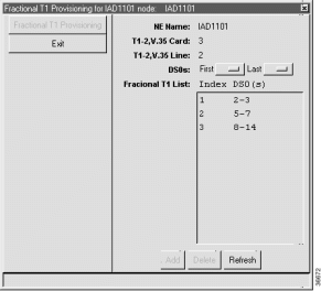
Step 2 Select Start Fractional T1 from the popup menu to open the provisioning window. (See Figure 12-1.)

Step 3 EMS displays a list of previously-provisioned fractional T1s in the Fractional T1 List. If you are creating a new fractional T1, you cannot use DS0 channels that are already part of another fractional T1.
Step 4 In the DS0s field drop-down menu, select the First and Last DS0s to define the range of DS0 channels.
Step 5 Click Add to provision the fractional T1. EMS adds the fractional T1 to the list and assigns it an index.
 |
Note To provision additional fractional T1s, repeat Step 4 and Step 5. |
Step 2 Click Delete. EMS removes the fractional T1 from the list.
Use the data link connection management interface (DLCMI) to provision Frame Relay parameters such as address protocol and local management interface (LMI).
 |
Note The Cisco IAD1101 does not support the proprietary Cisco Frame Relay encapsulation. You must use IETF encapsulation when configuring a Frame Relay link on the Cisco IAD1101. |

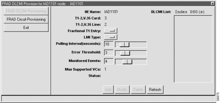
Step 2 Set the following fields according to your Frame Relay network:
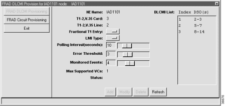
Step 3 Click Add to create the DLCMI. The DLCMI list shows the index and fractional T1 entry for the new DLCMI. (See Figure 12-3.)

Step 2 Remove any DLCIs associated with the DLCMI you intend to delete (see the "Deleting a DLCI" section).
Step 3 In the DLCMI list, select a DLCMI and click Delete. EMS removes the DLCMI from the list.
Frame Relay uses a data link connection identifier (DLCI) to identify a particular virtual circuit endpoint within a user access channel in a Frame Relay network.
To provision a DLCI for a DLCMI, complete the following steps starting in Cisco 6700 NodeView:
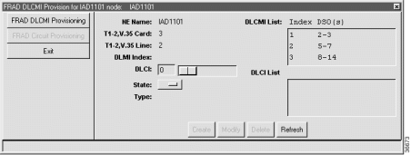
Step 2 Click FRAD Circuit Provisioning in the function bar. EMS launches the Frame Relay circuit provisioning window. (See Figure 12-4.)

Step 3 Click the entry in the DLCMI List (upper right) to select a DLCMI.
Step 4 Set the following fields for the DLCI to be created:
Step 5 Click Create to create the DLCI, or click Modify to change an existing DLCI. The DLCI List shows the new DLCI entry.
Step 2 Click Delete. EMS removes the DLCI from the DLCMI.
![]()
![]()
![]()
![]()
![]()
![]()
![]()
![]()
Posted: Mon Feb 5 13:03:15 PST 2001
All contents are Copyright © 1992--2001 Cisco Systems, Inc. All rights reserved.
Important Notices and Privacy Statement.