cc/td/doc/product/dsl_prod/6160
hometocprevnextglossaryfeedbacksearchhelp
PDF

Table Of Contents

Upgrading and Maintaining the Cisco 6160 System

6.1 Backing Up Software

6.2 Removing and Installing Hardware

6.2.1 xTU-C Line Card

6.2.2 Blank Faceplate

6.2.3 DS3+T1/E1 IMA NI-2 Card

6.2.4 DS3/2DS3 NI-2 Card

6.2.5 OC-3c/2DS3 NI-2 Card

6.2.6 OC-3c/OC-3c NI-2 Card

6.2.7 DS3/2DS3+8xT1 IMA I/O Card

6.2.8 DS3/2DS3 I/O Card

6.2.9 PEM

6.2.10 Blower Tray

6.3 Air Filter Maintenance

6.3.1 Required Tools and Equipment

6.3.2 Removing an Air Filter

6.3.3 Cleaning or Replacing the Air Filter


Upgrading and Maintaining the Cisco 6160 System


This chapter describes upgrade and maintenance procedures for the Cisco 6160 system. The chapter includes the following sections:

Backing Up Software

Removing and Installing Hardware

Air Filter Maintenance

6.1 Backing Up Software

We recommend that you maintain, on a TFTP server, current copies of three files for each Cisco 6160 system.

The Cisco IOS software image

The bootflash file

The configuration file (running-config)

If you keep copies of these files on a TFTP server, you can easily recover from a fault in an NI-2 card. You can simply replace the NI-2 card, then download the software image, bootflash and configuration file from the TFTP server. Remember to update your backup files whenever you change your configuration or upgrade your Cisco IOS software.


Note For more information about copying Cisco IOS software images and examples of the procedure, refer to the Configuration Guide for Cisco DSLAMs with NI-2.


To copy the Cisco IOS software image, the bootflash, and configuration file to a TFTP server, complete the following steps in privileged EXEC mode:


Step 1 Enter the dir command to display the names of the files:

6160# dir

Step 2 Enter a copy command to copy the IOS software file to the node TFTP server:

6160# copy flash:<image-name> tftp

Step 3 Enter a copy command to copy the bootflash file to the node TFTP server:

6160# copy bootflash:<image-name> tftp

Step 4 Enter a second copy command to copy the configuration file to the node TFTP server:

6160# copy running-config tftp


6.2 Removing and Installing Hardware

This section provides removal and installation procedures for the following field-replaceable unit (FRU) hardware components:

xTU-C Line Card

Blank Faceplate

DS3+T1/E1 IMA NI-2 Card

DS3/2DS3 NI-2 Card

OC-3c/2DS3 NI-2 Card

OC-3c/OC-3c NI-2 Card

DS3/2DS3+8xT1 IMA I/O Card

DS3/2DS3 I/O Card

PEM

Blower Tray


Note See the "General Maintenance Guidelines" section for installation and replacement practices for the Cisco 6160 system hardware components.


Caution Proper ESD protection is required whenever you handle Cisco equipment. Installation and maintenance personnel should be properly grounded by means of grounding straps to eliminate the risk of ESD damage to the equipment. Equipment is subject to ESD damage whenever it is removed from the chassis.

6.2.1 xTU-C Line Card

The following sections describe how to remove and install an xTU-C line card in the Cisco 6160 chassis.

6.2.1.1 Removing an xTU-C Line Card

Complete the following steps to remove an xTU-C line card from the chassis:


Caution When a line card is removed from the chassis, service is interrupted for the subscribers served by that line card.


Step 1 Connect a grounding strap to the ESD grounding jack on the chassis. See the "Preventing Electrostatic Discharge Damage" section for the ESD grounding jack location on the Cisco 6160.

Step 2 Use a flat-head screwdriver to move the locking tab from the locked to the unlocked position. Be sure to turn the locking tab so that it does not overlap the ejector lever as shown in Figure 6-1.

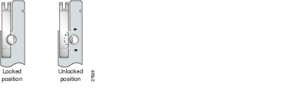
Figure 6-1 Positioning the Locking Tab for Line Card Removal and Installation

Step 3 Lift the ejector lever to disconnect the line card from the backplane.

Step 4 Carefully slide the line card out of the slot.

Either replace the line card that you remove, or insert a blank faceplate in the empty slot. For line card installation instructions, see the "Installing an xTU-C Line Card" section. For blank faceplate installation instructions, see the "Installing a Blank Faceplate" section.


Note Blank faceplates should occupy any empty line card slots in the chassis.


Warning Blank faceplates and cover panels serve three important functions: they prevent exposure to hazardous voltages and currents inside the chassis; they contain electromagnetic interference (EMI) that might disrupt other equipment; and they direct the flow of cooling air through the chassis. Do not operate the system unless all cards, faceplates, front covers, and rear covers are in place.


6.2.1.2 Installing an xTU-C Line Card

Complete the following steps to install an xTU-C line card in the chassis:


Note All cards must be fully seated in the chassis. Push on the faceplate of each card to be sure that the card is fully seated.


Step 1 Connect a grounding strap to the ESD grounding jack on the chassis. See the "Preventing Electrostatic Discharge Damage" section for the ESD grounding jack location on the Cisco 6160.

Step 2 Hold the line card vertically, with the faceplate toward you and the connectors facing the chassis slot.

Step 3 Align the line card edges with the guides at the top and bottom of the slot in the chassis.

Step 4 Lift the ejector lever and gently apply pressure to the faceplate while pushing the line card into the slot.

Figure 6-2 shows the line card installation for a Cisco 6160 chassis.

Figure 6-2 xTU-C Line Card Installation

Step 5 Push on the faceplate of the line card to fully seat the line card.

Step 6 Press down on the ejector lever to secure the line card and connect it to the backplane.

Step 7 Use a flat-head screwdriver to turn the locking tab so that it overlaps the ejector lever to prevent inadvertent dislodging. Figure 6-1 shows how to position the locking tab.

Step 8 Verify that the STATUS LED is solid green after the brief self-test. If the STATUS LED is not green after the self-test, see "Troubleshooting" for troubleshooting procedures.


Note If you are installing the line card for the first time, refer to the provisioning procedures in the appropriate software guide for your chassis.


6.2.2 Blank Faceplate

The following sections describe how to remove and install a blank faceplate in the Cisco 6160 chassis.


Warning Blank faceplates and cover panels serve three important functions: they prevent exposure to hazardous voltages and currents inside the chassis; they contain electromagnetic interference (EMI) that might disrupt other equipment; and they direct the flow of cooling air through the chassis. Do not operate the system unless all cards, faceplates, front covers, and rear covers are in place.


6.2.2.1 Removing a Blank Faceplate

Complete the following steps to remove a blank faceplate from the chassis:


Step 1 Connect a grounding strap to the ESD grounding jack on the chassis. See the "Preventing Electrostatic Discharge Damage" section for the ESD grounding jack location on the Cisco 6160.

Step 2 Lift the ejector lever to disconnect the blank faceplate from the backplane.

Step 3 Carefully slide the blank faceplate out of the slot.

Either replace the blank faceplate that you remove, or insert an xTU-C line card. For blank faceplate installation instructions, see the "Installing a Blank Faceplate" section. For line card installation instructions, see the "Installing an xTU-C Line Card" section.


Note Blank faceplates should occupy any empty line card slots in the chassis.


6.2.2.2 Installing a Blank Faceplate

Blank faceplates should occupy any empty line card slots in Cisco 6160 chassis. Blank faceplate installation is similar to line card installation.

Complete the following steps to install a blank faceplate from the chassis:


Step 1 Vertically align the blank faceplate edges with the guides at the top and bottom of the slot.

Step 2 Lift up on the ejector lever and gently apply pressure to the bottom of the faceplate while pushing the blank faceplate into the slot.

Step 3 Push on the faceplate to fully seat the blank faceplate.

Step 4 Press down on the ejector lever to secure the faceplate.


6.2.3 DS3+T1/E1 IMA NI-2 Card

The following sections describe how to remove and install a DS3+T1/E1 IMA NI-2 card.

6.2.3.1 Removing a DS3+T1/E1 IMA NI-2 Card

Complete the following steps to remove a DS3+T1/E1 IMA NI-2 card from the chassis. Accomplish each step completely before moving on to the next step.


Caution Service is interrupted to the entire system when the NI-2 card is removed unless a secondary NI-2 card is installed in the chassis. If a secondary NI-2 card is not installed, ensure that a service interruption is acceptable before proceeding.

If a secondary NI-2 card is installed in the chassis, removing the active NI-2 card causes a switchover to the standby NI-2 card, which interrupts data traffic for approximately 60 seconds.

Removing a standby NI-2 card does not interrupt service to the system.


Step 1 Connect a grounding strap to the ESD grounding jack on the chassis. See the "Preventing Electrostatic Discharge Damage" section for the ESD grounding jack location on the Cisco 6160.

Step 2 Disconnect the cable connected to the RJ-45 auxiliary port (AUX) on the NI-2 card, as necessary.

Step 3 Disconnect the cable connected to the system console port (CNSL) on the NI-2 card, as necessary.

Step 4 Disconnect the cable connected to the RJ-45 10BaseT receptacle (ENET) on the NI-2 card, as necessary.

Step 5 Use a flat-head screwdriver to move the locking tabs on the faceplate from the locked to the unlocked position. Be sure to turn the locking tabs so that they do not overlap the NI-2 card ejector levers, as shown in Figure 6-3.

Figure 6-3 Positioning the Locking Tab for NI-2 Card Removal and Installation

Step 6 Lift up on the ejector levers. This action disconnects the card from the backplane.

Step 7 Carefully slide the card out of the slot.

See the "Installing a DS3+T1/E1 IMA NI-2 Card" section for NI-2 card installation procedures.


6.2.3.2 Installing a DS3+T1/E1 IMA NI-2 Card

Complete the following steps to install a DS3+T1/E1 IMA NI-2 card in the chassis. Accomplish each step completely before moving on to the next step.


Note All cards must be fully seated in the chassis. Push on the faceplate of each card to be sure that the card is fully seated.


Step 1 Connect a grounding strap to the ESD grounding jack on the chassis. See the "Preventing Electrostatic Discharge Damage" section for the ESD grounding jack location on the Cisco 6160.

Step 2 Inspect the NI-2 card. Verify that the daughterboard is fully seated on the main board.

Step 3 Verify that the NI-2 card slot in the chassis has no bent pins.

Step 4 Hold the NI-2 card with the faceplate toward you and the connectors facing the chassis slot.

Step 5 Align the card edges with the slot guides in the chassis.

Step 6 Lift up on the ejector levers and gently apply pressure to the faceplate while pushing the card into the slot.

Figure 6-4 shows how to install an NI-2 card in a Cisco 6160 chassis.

Figure 6-4 NI-2 Card Installation in the Cisco 6160

Step 7 Push on the faceplate of the card to fully seat the card.

Step 8 Press down on the ejector levers to secure the card and connect it to the backplane.

Step 9 Use a flat-head screwdriver to turn the locking tabs on the faceplate so that they overlap the NI-2 card ejector levers to prevent inadvertent dislodging. Figure 6-3 shows how to position the locking tabs.

Step 10 Verify that the STATUS, ACTIVE, and POWER LEDs on the NI-2 card are solid green after the self-test is complete. This self-test procedure takes several minutes. If the LEDs are not green after the self-test, see "Troubleshooting" for troubleshooting procedures.


Note If you are installing the card for the first time, refer to the provisioning procedures in the Configuration Guide for Cisco DSLAMs with NI-2.


Step 11 Perform a software update if the STATUS LED on the NI-2 card is blinking.

Refer to the Configuration Guide for Cisco DSLAMs with NI-2 for software upgrade procedures.

Step 12 Connect the Ethernet to the management network.

a. Connect an Ethernet cable to the RJ-45 10BaseT receptacle (ENET) on the DS3+T1/E1 IMA NI-2 card faceplate.

b. Connect the other end of the Ethernet cable to the management network (for example, a LAN).

Step 13 Connect a VT100-compatible terminal to the system console port (CNSL) on the NI-2 card faceplate. Connect the terminal to a power source and set it up using the values shown in Table 6-1.

Table 6-1 Terminal Settings 

Baud rate

9600 (transmit and receive)

Character size

8 bits

Parity

None

Stop bits

1

Flow control

None


Step 14 Connect a terminal, a modem, or another serial device to the RJ-45 auxiliary port (AUX) on the NI-2 card faceplate. This step is optional.


6.2.4 DS3/2DS3 NI-2 Card

The following sections describe how to remove and install a DS3/2DS3 NI-2 card.

6.2.4.1 Removing a DS3/2DS3 NI-2 Card

Complete the following steps to remove a DS3/2DS3 NI-2 card from the chassis. Accomplish each step completely before moving on to the next step.


Caution Service is interrupted to the entire system when the NI-2 card is removed unless a secondary NI-2 card is installed in the chassis. If a secondary NI-2 card is not installed, ensure that a service interruption is acceptable before proceeding.

If a secondary NI-2 card is installed in the chassis, removing the active NI-2 card causes a switchover to the standby NI-2 card, which interrupts data traffic for approximately 60 seconds.

Removing a standby NI-2 card does not interrupt service to the system.


Step 1 Connect a grounding strap to the ESD grounding jack on the chassis. See the "Preventing Electrostatic Discharge Damage" section for the ESD grounding jack location on the Cisco 6160.

Step 2 Disconnect the cable connected to the RJ-45 auxiliary port (AUX) on the NI-2 card, as necessary.

Step 3 Disconnect the cable connected to the system console port (CNSL) on the NI-2 card, as necessary.

Step 4 Disconnect the cable connected to the RJ-45 10BaseT receptacle (ENET) on the NI-2 card, as necessary.

Step 5 Use a flat-head screwdriver to move the locking tabs on the faceplate from the locked to the unlocked position. Be sure to turn the locking tabs so that they do not overlap the ejector levers on the NI-2 card, as shown in Figure 6-3.

Step 6 Lift up on the ejector levers. This action disconnects the card from the backplane.

Step 7 Carefully slide the card out of the slot.

See the "Installing a DS3/2DS3 NI-2 Card" section for NI-2 card installation procedures.


6.2.4.2 Installing a DS3/2DS3 NI-2 Card

Complete the following steps to install a DS3/2DS3 NI-2 card in the chassis. Accomplish each step completely before moving on to the next step.


Note All cards must be fully seated in the chassis. Push on the faceplate of each card to be sure that the card is fully seated.


Step 1 Connect a grounding strap to the ESD grounding jack on the chassis. See the "Preventing Electrostatic Discharge Damage" section for the ESD grounding jack location on the Cisco 6160.

Step 2 Inspect the NI-2 card. Verify that the daughterboard is fully seated on the main board.

Step 3 Verify that the NI-2 card slot in the chassis has no bent pins.

Step 4 Hold the NI-2 card with the module faceplate toward you and the connectors facing the chassis slot.

Step 5 Vertically align the card edges with the guides at the top and bottom of slot 10 or slot 11 in the chassis.

Figure 6-4 shows how to install an NI-2 card in a Cisco 6160 chassis.

Step 6 Lift up on the ejector levers and gently apply pressure to the bottom of the faceplate while pushing the card into the slot.

Step 7 Push on the faceplate of each card to fully seat the card.

Step 8 Press down on the ejector levers to secure the card and connect it to the backplane.

Step 9 Use a flat-head screwdriver to turn the locking tabs on the faceplate so that they overlap the NI-2 card ejector levers to prevent inadvertent dislodging, as shown in Figure 6-3.


Note The network connection to the ATM switch and the subtending connections for the DS3/2DS3 NI-2 card are made from the I/O card. For more information on these connection procedures, see Chapter 3, "Installing a Cisco 6160 with a POTS Splitter Configuration," and Chapter 4, "Installing a Cisco 6160 Without a POTS Splitter Configuration."


Step 10 Verify that the STATUS, ACTIVE, and POWER LEDs on the NI-2 card are solid green after the self-test is complete. This self-test procedure takes several minutes. If the LEDs are not green after the self-test, see "Troubleshooting" for troubleshooting procedures.


Note If you are installing the card for the first time, refer to the provisioning procedures in the Configuration Guide for Cisco DSLAMs with NI-2.


Step 11 Perform a software update if the STATUS LED on the NI-2 card is blinking.

Refer to the Configuration Guide for Cisco DSLAMs with NI-2 for software upgrade procedures.

Step 12 Connect the Ethernet to the management network.

a. Connect an Ethernet cable to the RJ-45 10BaseT receptacle (ENET) on the NI-2 card faceplate.

b. Connect the other end of the Ethernet cable to the management network (for example, a LAN).

Step 13 Connect a VT100-compatible terminal to the system console port (CNSL) on the NI-2 card faceplate. Connect the terminal to a power source and set it up using the values that are shown in Table 6-1.

Step 14 Connect a terminal, a modem, or another serial device to the RJ-45 auxiliary port (AUX) on the NI-2 card faceplate. This step is optional.


6.2.5 OC-3c/2DS3 NI-2 Card

The following sections describe how to remove and install an OC-3c/2DS3 NI-2 card.

6.2.5.1 Removing an OC-3c/2DS3 NI-2 Card

Complete the following steps to remove an OC-3c/2DS3 NI-2 card from the chassis. Accomplish each step completely before moving on to the next step.


Caution Service is interrupted to the entire system when the NI-2 card is removed unless a secondary NI-2 card is installed in the chassis. If a secondary NI-2 card is not installed, ensure that a service interruption is acceptable before proceeding.

If a secondary NI-2 card is installed in the chassis, removing the active NI-2 card causes a switchover to the standby NI-2 card, which interrupts data traffic for approximately 60 seconds.

Removing a standby NI-2 card does not interrupt service to the system.


Step 1 Connect a grounding strap to the ESD grounding jack on the chassis. See the "Preventing Electrostatic Discharge Damage" section for the ESD grounding jack location on the Cisco 6160.

Step 2 Disconnect the cable connected to the RJ-45 auxiliary port (AUX) on the NI-2 card, as necessary.

Step 3 Disconnect the cable connected to the system console port (CNSL) on the NI-2 card, as necessary.

Step 4 Disconnect the cable connected to the RJ-45 10BaseT receptacle (ENET) on the NI-2 card, as necessary.

Step 5 Disconnect the ATM switch receive cable from the TRNK 1 TX optical interface connector on the NI-2 card.

Step 6 Disconnect the ATM switch transmit cable from the TRNK 1 RX optical interface connector on the NI-2 card.

Step 7 Use a flat-head screwdriver to move the locking tabs on the faceplate from the locked to the unlocked position. Be sure to turn the locking tabs so that they do not overlap the NI-2 card ejector levers, as shown in Figure 6-3.

Step 8 Lift up on the ejector levers. This action disconnects the card from the backplane.

Step 9 Carefully slide the card out of the slot.

See the "Installing an OC-3c/2DS3 NI-2 Card" section for NI-2 card installation procedures.


6.2.5.2 Installing an OC-3c/2DS3 NI-2 Card

Complete the following steps to install an OC-3c/2DS3 NI-2 card in the chassis. Accomplish each step completely before moving on to the next step.


Note All cards must be fully seated in the chassis. Push on the faceplate of each card to be sure that the card is fully seated.


Step 1 Connect a grounding strap to the ESD grounding jack on the chassis. See the "Preventing Electrostatic Discharge Damage" section for the ESD grounding jack location on the Cisco 6160.

Step 2 Inspect the NI-2 card. Verify that the daughterboard is fully seated on the main board.

Step 3 Verify that the NI-2 card slot in the chassis has no bent pins.

Step 4 Hold the NI-2 card with the faceplate toward you and the connectors facing the chassis slot.

Step 5 Vertically align the card edges with the guides at the top and bottom of slot 10 or slot 11 in the chassis.

Figure 6-4 shows how to install an NI-2 card in a Cisco 6160 chassis.

Step 6 Lift up on the ejector levers and gently apply pressure to the bottom of the faceplate while pushing the card into the slot.

Step 7 Push on the faceplate of each card to fully seat the card.

Step 8 Press down on the ejector levers to secure the card and connect it to the backplane.

Step 9 Use a flat-head screwdriver to turn the locking tabs on the faceplate so that they overlap the NI-2 card ejector levers to prevent inadvertent dislodging, as shown in Figure 6-3.

Step 10 Verify that the STATUS, ACTIVE, and POWER LEDs on the NI-2 card are solid green after the self-test is complete. This self-test procedure takes several minutes. If the LEDs are not green after the self-test, see "Troubleshooting" for troubleshooting procedures.


Note If you are installing the card for the first time, refer to the provisioning procedures in the Configuration Guide for Cisco DSLAMs with NI-2.


Step 11 Perform a software update if the STATUS LED on the NI-2 card is blinking.

Refer to the Configuration Guide for Cisco DSLAMs with NI-2 for software upgrade procedures.

Step 12 Attach the receive cable from the ATM switch to the TRNK 1 TX optical interface connector on the OC-3c/2DS3 NI-2 card. See Figure 1-16 for the OC-3c network trunk interface connection location.

The TRNK 1 TX connector is the one closest to the top of the faceplate. The TRNK 1 RX connector is closer to the bottom of the faceplate. The connector IDs are silkscreened inside the faceplate inset.

Step 13 Attach the transmit cable from the ATM switch to the TRNK 1 RX optical interface connector on the OC-3c/2DS3 NI-2 card. See Figure 1-16 for the OC-3c network trunk interface connection location.


Note The subtending connections for the OC-3c/2DS3 NI-2 card are made from the I/O card. For more information on these connection procedures, see Chapter 3, "Installing a Cisco 6160 with a POTS Splitter Configuration," and Chapter 4, "Installing a Cisco 6160 Without a POTS Splitter Configuration."


Step 14 Connect the Ethernet to the management network.

a. Connect an Ethernet cable to the RJ-45 10BaseT receptacle (ENET) on the NI-2 card faceplate.

b. Connect the other end of the cable to the management network (for example, a LAN).

Step 15 Connect a VT100-compatible terminal to the system console port (CNSL) on the NI-2 card faceplate. Connect the terminal to a power source and set it up using the values that are shown in Table 6-1.

Step 16 Connect a terminal, a modem, or another serial device to the RJ-45 auxiliary port (AUX) on the NI-2 card faceplate. This step is optional.


6.2.6 OC-3c/OC-3c NI-2 Card

The following sections describe how to remove and install an OC-3c/OC-3c NI-2 card.

6.2.6.1 Removing an OC-3c/OC-3c NI-2 Card

Complete the following steps to remove an OC-3c/OC-3c NI-2 card from the chassis. Accomplish each step completely before moving on to the next step.


Caution Service is interrupted to the entire system when the NI-2 card is removed unless a secondary NI-2 card is installed in the chassis. If a secondary NI-2 card is not installed, ensure that a service interruption is acceptable before proceeding.

If a secondary NI-2 card is installed in the chassis, removing the active NI-2 card causes a switchover to the standby NI-2 card, which interrupts data traffic for approximately 60 seconds.

Removing a standby NI-2 card does not interrupt service to the system.


Step 1 Connect a grounding strap to the ESD grounding jack on the chassis. See the "Preventing Electrostatic Discharge Damage" section for the ESD grounding jack location on the Cisco 6160.

Step 2 Disconnect the cable connected to the RJ-45 auxiliary port (AUX) on the NI-2 card, as necessary.

Step 3 Disconnect the cable connected to the system console port (CNSL) on the NI-2 card, as necessary.

Step 4 Disconnect the cable connected to the RJ-45 10BaseT receptacle (ENET) on the NI-2 card, as necessary.

Step 5 Disconnect the ATM switch receive cable from the TRNK 1 TX optical interface connector on the NI-2 card.

Step 6 Disconnect the ATM switch transmit cable from the TRNK 1 RX optical interface connector on the NI-2 card.

Step 7 Disconnect the SBTD 2 RX optical interface connector on the NI-2 card, as necessary.

Step 8 Disconnect the SBTD 2 TX optical interface connector on the NI-2 card, as necessary.

Step 9 Use a flat-head screwdriver to move the locking tabs on the faceplate from the locked to the unlocked position. Be sure to turn the locking tabs so that they do not overlap the NI-2 card ejector levers, as shown in Figure 6-3.

Step 10 Lift up on the ejector levers. This action disconnects the card from the backplane.

Step 11 Carefully slide the card out of the slot.

See the "Installing an OC-3c/OC-3c NI-2 Card" section for NI-2 card installation procedures.


6.2.6.2 Installing an OC-3c/OC-3c NI-2 Card

Complete the following steps to install an OC-3c/OC-3c NI-2 card in the chassis. Accomplish each step completely before moving on to the next step.


Note All cards must be fully seated in the chassis. Push on the faceplate of each card to be sure that the card is fully seated.


Step 1 Connect a grounding strap to the ESD grounding jack on the chassis. See the "Preventing Electrostatic Discharge Damage" section for the ESD grounding jack location on the Cisco 6160.

Step 2 Inspect the NI-2 card. Verify that the daughterboard is fully seated on the main board.

Step 3 Verify that the NI-2 card slot in the chassis has no bent pins.

Step 4 Hold the NI-2 card with the faceplate toward you and the connectors facing the chassis slot.

Step 5 Align the card edges with the slot guides in the chassis.

Figure 6-4 shows how to install an NI-2 card in a Cisco 6160 chassis.

Step 6 Lift up on the ejector levers and gently apply pressure to the bottom of the faceplate while pushing the card into the slot.

Step 7 Push on the faceplate of each card to fully seat the card.

Step 8 Press down on the ejector levers to secure the card and connect it to the backplane.

Step 9 Use a flat-head screwdriver to turn the locking tabs on the faceplate so that they overlap the NI-2 card ejector levers to prevent inadvertent dislodging, as shown in Figure 6-3.

Step 10 Verify that the STATUS, ACTIVE, and POWER LEDs on the NI-2 card are solid green after the self-test is complete. This self-test procedure takes several minutes. If the STATUS LEDs are not green after the self-test, see "Troubleshooting" for troubleshooting procedures.

Step 11 Perform a software update if the STATUS LED on the NI-2 card is blinking.


Note Refer to the Configuration Guide for Cisco DSLAMs with NI-2 for software upgrade procedures.


Step 12 Attach the receive cable from the ATM switch to the TRNK 1 TX optical interface connector on the OC-3c/2DS3 NI-2 card. See Figure 1-17 for the OC-3c network trunk interface connection location.

The TRNK 1 TX connector is the one closest to the top of the faceplate. The TRNK 1 RX connector is closer to the bottom of the faceplate. The connector IDs are silkscreened inside the faceplate inset.

Step 13 Attach the transmit cable from the ATM switch to the TRNK 1 RX optical interface connector on the OC-3c/2DS3 NI-2 card. See Figure 1-17 for the OC-3c network trunk interface connection location.


Note To cable the chassis for OC-3c subtending, see the appropriate installation chapter in this guide.


Step 14 Reconnect the SBTD 2 optical interface connectors (RX and TX) on the NI-2 card, as necessary.


Note To cable the chassis for OC-3c subtending, see Chapter 3, "Installing a Cisco 6160 with a POTS Splitter Configuration," or Chapter 4, "Installing a Cisco 6160 Without a POTS Splitter Configuration."


Step 15 Connect the Ethernet to the management network.

a. Connect an Ethernet cable to the RJ-45 10BaseT receptacle (ENET) on the OC-3c/OC-3c NI-2 card faceplate.

b. Connect the other end of the cable to the management network (for example, a LAN).

Step 16 Connect a VT100-compatible terminal to the system console port (CNSL) on the NI-2 card faceplate. Connect the terminal to a power source and set it up using the values that are shown in Table 6-1.

Step 17 Connect a terminal, a modem, or another serial device to the RJ-45 auxiliary port (AUX) on the NI-2 card faceplate. This step is optional.


6.2.7 DS3/2DS3+8xT1 IMA I/O Card

The following sections describe how to remove or install a DS3/2DS3+8xT1 IMA I/O card.


Caution Static voltages as low as 30 volts can cause latent damage to circuitry on the I/O card. Observe all standard antistatic procedures (for example, wear a ground strap).

6.2.7.1 Removing a DS3/2DS3+8xT1 IMA I/O Card

Complete the following steps to remove the DS3/2DS3+8xT1 IMA I/O card from the chassis backplane:


Caution To prevent the system from powering up, do not install the fuses at this time. If the fuses are already installed in the fuse and alarm panel, remove them. You can replace the fuses after the system is installed and connected.

The fuse and alarm panel is not provided by Cisco.


Tip Cisco recommends that you label each cable and wire at both ends to identify its destination.


Step 1 Connect a grounding strap to the ESD grounding jack on the chassis. See the "Preventing Electrostatic Discharge Damage" section for the ESD grounding jack location on the Cisco 6160.

Step 2 Power off the Cisco 6160.

a. Type the following command to save the configuration changes to NVRAM:

DSLAM# copy running-config startup-config

b. Set the circuit breakers on both power entry modules (PEMs) to the OFF (0) position.

Step 3 Mark and disconnect all DS3 coaxial cables from the six BNC connectors (DS3 Port 1 through Port 3) on the I/O card, as necessary. Each port has a TX and an RX connection.

See Figure 1-19 for the DS3 BNC connector locations.

Step 4 Mark and disconnect all T1 wires from the eight RJ-48C receptacles (T1 Port 1 through Port 8) on the I/O card, as necessary.

See Figure 1-19 for the T1 receptacle locations.

Step 5 Mark and disconnect all wires from the I/O card wire-wrap pins.

See Figure 1-19 for the wire-wrap pin locations.

Step 6 Use a Phillips-head screwdriver to remove the ten screws from the I/O card EMI cover, as shown in Figure 6-5.

Figure 6-5 DS3/2DS3+8xT1 IMA I/O Card EMI Cover Removal

Step 7 Carefully lift the EMI cover off of the I/O card.

Step 8 Use a 1/4 inch socket driver or wrench to remove the ten standoff screws and washers that attach the I/O card to the chassis, as shown in Figure 6-6.

Figure 6-6 DS3/2DS3+8xT1 IMA I/O Card Removal

Step 9 Grasp the sides, or top and bottom, of the I/O card, and carefully pull the I/O card away from the P3 and P9 connectors on the Cisco 6160 backplane.

Step 10 Place the I/O card in an antistatic bag or in a box lined with antistatic material.

Step 11 Store the removed screws, standoff screws, washers, and EMI cover in a safe place for reinstallation.

See the "Installing a DS3/2DS3+8xT1 IMA I/O Card" section for I/O card installation procedures.


6.2.7.2 Installing a DS3/2DS3+8xT1 IMA I/O Card

Complete the following steps to install the DS3/2DS3+8xT1 IMA I/O card from the chassis backplane:


Caution To prevent the system from powering up, do not install the fuses at this time. If the fuses are already installed in the fuse and alarm panel, remove them. You can replace the fuses after the system is installed and connected.

The fuse and alarm panel is not provided by Cisco.


Step 1 Connect a grounding strap to the ESD grounding jack on the chassis. See the "Preventing Electrostatic Discharge Damage" section for the ESD grounding jack location on the Cisco 6160.

Step 2 Verify that your configuration is saved to NVRAM.

Step 3 Verify that the circuit breakers on both PEMs are turned to the OFF (0) position.

Step 4 Use a 1/4 inch socket driver or wrench to tighten the two standoff screws. One standoff screw is located to the left of the P9 connector and the other is located to the right of the P3 connector.


Caution Be careful not to damage backplane circuitry when you tighten the standoff screws on the backplane.

Step 5 Hold the I/O card vertically with its component side (primary side) facing you and align the I/O card over the two standoff screws.

Step 6 Carefully press J15 and J16 receptacles on the I/O card onto the P3 and P9 connectors on the chassis backplane until the I/O card is in place and against the two standoff screws, as shown in Figure 6-7.

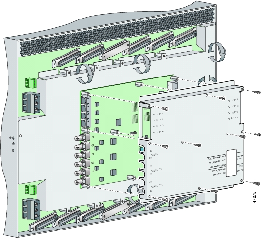
Figure 6-7 DS3/2DS3+8xT1 IMA I/O Card Placement on P3 and P9 Connectors

Step 7 Ensure that all of the mounting holes on the I/O card line up with the standoff screw holes on the backplane.

Step 8 Fasten the I/O card to the Cisco 6160 backplane by inserting the ten standoff screws and washers into the ten standoff screw holds in the I/O card, as shown in Figure 6-7.

Step 9 Use a 1/4 inch socket driver or wrench to tighten the ten standoff screws as necessary.


Caution Do not exceed a torque control of 4 foot-pounds. Doing so can damage the I/O card.

Step 10 Align the ten mounting holes on the EMI cover with the ten standoff screws installed on the I/O card.

Step 11 Use a Phillips-head screwdriver and ten screws to attach the EMI cover to the I/O card, as shown in Figure 6-8.


Caution Do not exceed a torque control of 4 foot-pounds.

Figure 6-8 DS3/2DS3+8xT1 IMA I/O Card EMI Cover Installation

Step 12 If you disconnected the wire from the wire-wrap pins in the "Removing a DS3/2DS3+8xT1 IMA I/O Card" section, reconnect them.

Step 13 If you disconnected the T1 wires from the RJ-48C receptacles in the "Removing a DS3/2DS3+8xT1 IMA I/O Card" section, reconnect them.

Step 14 If you disconnected the DS3 coaxial cables from the BNC connectors in the "Removing a DS3/2DS3+8xT1 IMA I/O Card" section, reconnect them.

Step 15 Set the circuit breakers on each PEM to the ON (1) position.


Note The OUT FAIL LED might blink briefly.


Step 16 Verify that the INPUT OK LED is green.


Note If the INPUT OK LED is not green or if other issues arise, see "Troubleshooting" for troubleshooting procedures.


Step 17 Reboot the system to reassociate the system MAC address.

Step 18 Confirm that the Cisco IOS software recognizes the new I/O card.

a. Type the following command:

DSLAM# show hardware

b. Scroll through the data and locate the I/O card information.

The information displayed on the screen will be similar to the following output:


Note The command output below is an example display. Slots 1 through 9 and 12 through 34 are available for line cards and slot 11 is for a secondary NI-2 card.


Chassis Type: C6160
I/O Card: 6160-DS3+8T1-IO
Slot 1 : EMPTY Slot 19: EMPTY
Slot 2 : EMPTY Slot 20: EMPTY
Slot 3 : EMPTY Slot 21: EMPTY
Slot 4 : EMPTY Slot 22: EMPTY
Slot 5 : EMPTY Slot 23: EMPTY
Slot 6 : EMPTY Slot 24: EMPTY
Slot 7 : EMPTY Slot 25: EMPTY
Slot 8 : EMPTY Slot 26: EMPTY
Slot 9 : EMPTY Slot 27: EMPTY
Slot 10:NI-2-155MM-155MM
Slot 11:EMPTY
Slot 12: EMPTY Slot 28: EMPTY
Slot 13: EMPTY Slot 29: EMPTY
Slot 14: EMPTY Slot 30: EMPTY
Slot 15: EMPTY Slot 31: EMPTY
Slot 16: EMPTY Slot 32: EMPTY
Slot 17: EMPTY Slot 33: EMPTY
Slot 18: EMPTY Slot 34: EMPTY
Fan Module 1: Present 2: Present
Power Supply Module 1: 6160-PEM-DC
Power Supply Module 2: EMPTY


Note If the information displays as "Unreadable" or "Unknown", the I/O card was not installed properly or a problem exists with the I/O card. Install the I/O card again by following the procedures in this section. If the I/O card is still not recognized by the system, see "Troubleshooting" for troubleshooting procedures.


6.2.8 DS3/2DS3 I/O Card

The following sections describe how to remove or install a DS3/2DS3 I/O card.


Caution Static voltages as low as 30 volts can cause latent damage to circuitry on the I/O card. Observe all standard antistatic procedures (for example, wear a ground strap).

6.2.8.1 Removing a DS3/2DS3 I/O Card

Complete the following steps to remove the DS3/2DS3 I/O card from the chassis backplane:


Caution To prevent the system from powering up, do not install the fuses at this time. If the fuses are already installed in the fuse and alarm panel, remove them. You can replace the fuses after the system is installed and connected.

The fuse and alarm panel is not provided by Cisco.


Tip Cisco recommends that you label each cable and wire at both ends to identify its destination.


Step 1 Connect a grounding strap to the ESD grounding jack on the chassis. See the "Preventing Electrostatic Discharge Damage" section for the ESD grounding jack location on the Cisco 6160.

Step 2 Power off the Cisco 6160.

a. Type the following command to save the configuration changes to NVRAM:

DSLAM# copy running-config startup-config

b. Set the circuit breakers on both power entry modules (PEMs) to the OFF (0) position.

Step 3 Mark and disconnect all DS3 coaxial cables from the six BNC connectors (DS3 Port 1 through Port 3) on the I/O card, as necessary. Each port has a TX and an RX connection.

See Figure 1-23 for the DS3 BNC connector locations.

Step 4 Mark and disconnect all wires from the I/O card wire-wrap pins.

See Figure 1-23 for the wire-wrap pin locations.

Step 5 Use a Phillips-head screwdriver to remove the ten screws from the I/O card EMI cover, as shown in Figure 6-9.

Figure 6-9 DS3/2DS3 I/O Card EMI Cover Removal

Step 6 Carefully lift the EMI cover off of the I/O card.

Step 7 Use a 1/4 inch socket driver or wrench to remove the ten standoff screws and washers that attach the I/O card to the chassis, as shown in Figure 6-10.

Figure 6-10 DS3/2DS3 I/O Card Removal

Step 8 Grasp the sides, or top and bottom, of the I/O card, and carefully pull the I/O card away from the P3 and P9 connectors on the Cisco 6160 backplane.

Step 9 Place the I/O card in an antistatic bag or in a box lined with antistatic material.

Step 10 Store the removed screws, standoff screws, washers, and EMI cover in a safe place for reinstallation.

See the "Installing a DS3/2DS3 I/O Card" section for I/O card installation procedures.


6.2.8.2 Installing a DS3/2DS3 I/O Card

Complete the following steps to install the DS3/2DS3 I/O card from the chassis backplane:


Caution To prevent the system from powering up, do not install the fuses at this time. If the fuses are already installed in the fuse and alarm panel, remove them. You can replace the fuses after the system is installed and connected.

The fuse and alarm panel is not provided by Cisco.


Step 1 Connect a grounding strap to the ESD grounding jack on the chassis. See the "Preventing Electrostatic Discharge Damage" section for the ESD grounding jack location on the Cisco 6160.

Step 2 Verify that your configuration is saved to NVRAM.

Step 3 Verify that the circuit breakers on both PEMs are turned to the OFF (0) position.

Step 4 Use a 1/4 inch socket driver or wrench to tighten the two standoff screws. One standoff screw is located to the left of the P9 connector and the other is located to the right of the P3 connector.


Caution Be careful not to damage backplane circuitry when you tighten the standoff screws on the backplane.

Step 5 Hold the I/O card vertically with its component side (primary side) facing you and align the I/O card over the two standoff screws.

Step 6 Carefully press J15 and J16 receptacles on the I/O card onto the P3 and P9 connectors on the chassis backplane until the I/O card is in place and against the two standoff screws, as shown in Figure 6-11.

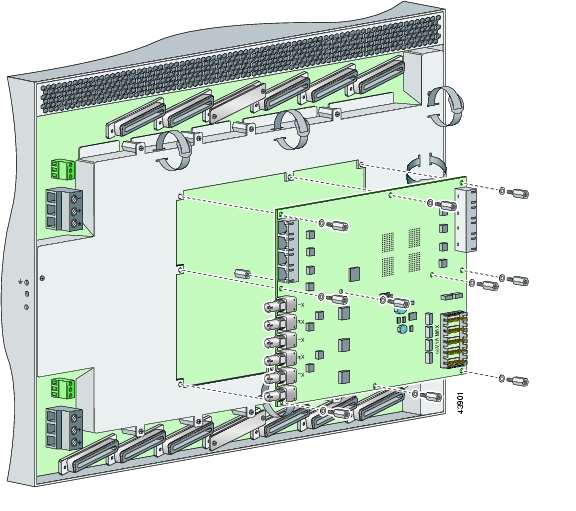
Figure 6-11 DS3/2DS3 I/O Card Placement on P3 and P9 Connectors

Step 7 Ensure that all of the mounting holes on the I/O card line up with the standoff screw holes on the backplane.

Step 8 Fasten the I/O card to the Cisco 6160 backplane by inserting the ten standoff screws and washers into the ten standoff screw holds in the I/O card, as shown in Figure 6-11.

Step 9 Use a 1/4 inch socket driver or wrench to tighten the ten standoff screws as necessary.


Caution Do not exceed a torque control of 4 foot-pounds. Doing so can damage the I/O card.

Step 10 Align the ten mounting holes on the EMI cover with the ten standoff screws installed on the I/O card.

Step 11 Use a Phillips-head screwdriver and ten screws to attach the EMI cover to the I/O card, as shown in Figure 6-12.


Caution Do not exceed a torque control of 4 foot-pounds.

Figure 6-12 DS3/2DS3 I/O Card EMI Cover Installation

Step 12 If you disconnected the wire from the wire-wrap pins in the "Removing a DS3/2DS3+8xT1 IMA I/O Card" section, reconnect them.

Step 13 If you disconnected the DS3 coaxial cables from the BNC connectors in the "Removing a DS3/2DS3+8xT1 IMA I/O Card" section, reconnect them.

Step 14 Set the circuit breakers on each PEM to the ON (1) position.


Note The OUT FAIL LED might blink briefly.


Step 15 Verify that the INPUT OK LED is green.


Note If the INPUT OK LED is not green or if other issues arise, see "Troubleshooting" for troubleshooting procedures.


Step 16 Reboot the system to reassociate the system MAC address.

Step 17 Confirm that the Cisco IOS software recognizes the new I/O card.

a. Type the following command:

DSLAM# show hardware

b. Scroll through the data and locate the I/O card information.

The information displayed on the screen will be similar to the following output:


Note The command output below is an example display. Slots 1 through 9 and 12 through 34 are available for line cards and slot 11 is for a secondary NI-2 card.


I/O Card EEPROM:
Hardware Revision : 1.0
Part Number : 800-06477-01
Board Revision : 05
Deviation Number : 0-0
Fab Version : 02
PCB Serial Number : SAD0407009H
RMA Test History : 00
RMA Number : 0-0-0-0
RMA History : 00
Chassis MAC Address : 0030.96fe.9700
MAC Address block size : 1024
CLEI Code : UNASSIGNED
Asset Identifier :
EEPROM format version 4
EEPROM contents (hex):
0x00: 04 FF 40 01 CB 41 01 00 C0 46 03 20 00 19 4D 01
0x10: 42 30 35 80 00 00 00 00 02 02 C1 8B 53 41 44 30
0x20: 34 30 37 30 30 39 48 03 00 81 00 00 00 00 04 00
0x30: C3 06 00 30 96 FE 97 00 43 04 00 C6 8A 55 4E 41
0x40: 53 53 49 47 4E 45 44 CC 20 00 00 00 00 00 00 00
0x50: 00 00 00 00 00 00 00 00 00 00 00 00 00 00 00 00
0x60: 00 00 00 00 00 00 00 00 00 FF FF FF FF FF FF FF
0x70: FF FF FF FF FF FF FF FF FF FF FF FF FF FF FF FF
0x80: FF FF FF FF FF FF FF FF FF FF FF FF FF FF FF FF
0x90: FF FF FF FF FF FF FF FF FF FF FF FF FF FF FF FF
0xA0: FF FF FF FF FF FF FF FF FF FF FF FF FF FF FF FF
0xB0: FF FF FF FF FF FF FF FF FF FF FF FF FF FF FF FF
0xC0: FF FF FF FF FF FF FF FF FF FF FF FF FF FF FF FF
0xD0: FF FF FF FF FF FF FF FF FF FF FF FF FF FF FF FF
0xE0: FF FF FF FF FF FF FF FF FF FF FF FF FF FF FF FF
0xF0: FF FF FF FF FF FF FF FF FF FF FF FF FF FF FF FF

Note If the information displays as "Unreadable" or "Unknown", the I/O card was not installed properly or a problem exists with the I/O card. Install the I/O card again by following the procedures in this section. If the I/O card is still not recognized by the system, see "Troubleshooting" for troubleshooting procedures.


6.2.9 PEM

The following sections describe how to remove or install a power entry module (PEM).


Note All modules must be fully seated in the chassis. Push on the faceplate of each module to be sure that the card is fully seated.


6.2.9.1 Removing a PEM

Complete the following steps to remove a PEM from the chassis:


Caution If you remove a PEM from the Cisco 6160 chassis in which a secondary PEM is installed and providing power, the chassis continues to operate. If you remove the only operating PEM from the chassis, power down the system before you begin.


Step 1 Connect a grounding strap to the ESD grounding jack on the chassis. See the "Preventing Electrostatic Discharge Damage" section for the ESD grounding jack location on the Cisco 6160.

Step 2 Power down the Cisco 6160, as necessary.

a. Type the following command to save the configuration changes to NVRAM:

DSLAM# copy running-config startup-config

b. Set the circuit breaker on the operating PEM to the OFF (0) position.

Step 3 Use a Phillips-head screwdriver to loosen the two captive screws on the front of the PEM.

Step 4 Grasp the handle on the right side of the PEM and pull the PEM from the slot.

Step 5 Place the PEM in an antistatic bag or in a box lined with antistatic material.

See the "Installing a PEM" section for PEM installation procedures.


6.2.9.2 Installing a PEM

Complete the following steps to install a PEM in the chassis:


Note Connect each Cisco 6160 PEM to a separate fuse. Do not power the components in the rack by chaining them together. See the appropriate installation chapter for power and ground procedures.


Step 1 Connect a grounding strap to the ESD grounding jack on the chassis. See the "Preventing Electrostatic Discharge Damage" section for the ESD grounding jack location on the Cisco 6160.

Step 2 Verify that your configuration is saved to NVRAM.

Step 3 Verify that the circuit breaker on the PEM is turned to the OFF (0) position, as necessary.

Step 4 Verify that the power and ground wires are connected to the power terminal block located on the backplane, directly behind the PEM that you are installing. See the appropriate installation chapter for procedures to connect power and ground to the power terminal block.

Step 5 Grasp the handle on the right side of the PEM to slide it into the appropriate slot. Verify that the connector on the back of the PEM mates with the backplane connector and guide pins.

Figure 6-13 shows the installation of the PEM in a Cisco 6160 chassis.

Figure 6-13 PEM Installation

Step 6 Use a Phillips-head screwdriver to tighten the two captive screws to secure the PEM in place.

Step 7 Power on the PEM by setting the circuit breaker to the ON (1) position, as necessary.


Note The OUT FAIL LED might blink briefly.


Step 8 Verify that the INPUT OK LED is green.


Note If the INPUT OK LED is not green or if other issues arise, see "Troubleshooting" for troubleshooting procedures.


Step 9 Confirm that the Cisco IOS software recognizes the new PEM.

a. Type the following command:

DSLAM# show hardware chassis

b. Scroll through the data and locate the PEM information.

The information displayed on the screen will be similar to the following output:

Slot 2 Power Module EEPROM:
Hardware Revision : 1.0
Part Number : 34-1259-01
Deviation Number : 0-0
RMA Test History : 00
RMA Number : 0-0-0-0
RMA History : 00
Chassis Serial Number : 000000PP830
Power Supply Type : DC
CLEI Code : ABCDEFGHIJ
Asset Identifier :
EEPROM format version 4
EEPROM contents (hex):
0x00: 04 FF 41 01 00 82 22 04 EB 01 80 00 00 00 00 03
0x10: 00 81 00 00 00 00 04 00 C2 8B 30 30 30 30 30 30
0x20: 50 50 38 33 30 0B 01 C6 8A 41 42 43 44 45 46 47
0x30: 48 49 4A CC 20 00 00 00 00 00 00 00 00 00 00 00
0x40: 00 00 00 00 00 00 00 00 00 00 00 00 00 00 00 00
0x50: 00 00 00 00 00 FF FF FF FF FF FF FF FF FF FF FF
0x60: FF FF FF FF FF FF FF FF FF FF FF FF FF FF FF FF
0x70: FF FF FF FF FF FF FF FF FF FF FF FF FF FF FF FF
0x80: FF FF FF FF FF FF FF FF FF FF FF FF FF FF FF FF
0x90: FF FF FF FF FF FF FF FF FF FF FF FF FF FF FF FF
0xA0: FF FF FF FF FF FF FF FF FF FF FF FF FF FF FF FF
0xB0: FF FF FF FF FF FF FF FF FF FF FF FF FF FF FF FF
0xC0: FF FF FF FF FF FF FF FF FF FF FF FF FF FF FF FF
0xD0: FF FF FF FF FF FF FF FF FF FF FF FF FF FF FF FF
0xE0: FF FF FF FF FF FF FF FF FF FF FF FF FF FF FF FF
0xF0: FF FF FF FF FF FF FF FF FF FF FF FF FF FF FF FF


Note If the information displays as "Unreadable" or "Unknown", the PEM was not installed properly or a problem exists with the PEM. Install the PEM again by following the procedures in this section. If the PEM is still not recognized by the system, see "Troubleshooting" for troubleshooting procedures.


Step 10 View PEM operating information.

a. Type the following command:

DSLAM# show environment all

b. Scroll through the data and locate the PEM information.

If the PEM is operating properly, the information displayed on the screen will be similar to the following output:

                  Slot 1     Slot 2
Power Modules:
Present:          Yes        Yes
Faults:           No         No
Internal Temp:    21C/69 F   22C/71 F
External Temp 1:  20C/68 F   23C/73 F
External Temp 2:  20C/68 F   20C/68 F
Temp Alarms:      No         No


Note If a problem exists with the PEM operating information, see "Troubleshooting" for troubleshooting procedures.


6.2.10 Blower Tray

The following sections describe how to remove or install the Cisco 6160 blower tray.


Caution Proper ESD protection is required whenever you handle Cisco equipment. Installation and maintenance personnel should be properly grounded by means of grounding straps to eliminate the risk of ESD damage to the equipment. Equipment is subject to ESD damage whenever it is removed from the chassis.

6.2.10.1 Removing a Blower Tray

Complete the following steps to remove the blower tray from the chassis:


Warning Before you remove the blower tray from its slot, make sure you grasp it firmly to prevent it from slipping to the floor. This unit is heavier than it appears.


Step 1 Connect a grounding strap to the ESD grounding jack on the chassis. See the "Preventing Electrostatic Discharge Damage" section for the ESD grounding jack location on the Cisco 6160.

Step 2 Use a Phillips-head screwdriver to loosen the two captive screws on the blower tray faceplate.

Step 3 Grasp the two captive screws, and slowly slide the blower tray out until it catches. (Do not pull the unit completely out. It is supported only by the captive screws.)

Step 4 Locate and press the safety catch (see Figure 6-14) on the right side of the blower tray.

Step 5 While pressing the safety catch, firmly grasp the sides of the blower tray and slowly remove the blower tray from its slot.

See the "Installing a Blower Tray" section for blower tray installation procedures.


6.2.10.2 Installing a Blower Tray

Complete the following steps to install the blower tray in the chassis:


Step 1 Connect a grounding strap to the ESD grounding jack on the chassis. See the "Preventing Electrostatic Discharge Damage" section for the ESD grounding jack location on the Cisco 6160.

Step 2 Slide the blower tray into the blower tray slot of the Cisco 6160.

Figure 6-14 shows the installation of the blower tray in the Cisco 6160 chassis.

Figure 6-14 Blower Tray Installation in the Cisco 6160 Chassis

Step 3 Press the blower tray into its slot. Ensure that the blower tray connector mates with the connector on the backplane.

Step 4 Use a Phillips-head screwdriver to tighten the two captive screws on the blower tray faceplate.

Step 5 Verify that the INPUT OK LED is green. At startup, the LED may blink red momentarily before it changes to green. This is normal at startup.


Note If the INPUT OK LED is not green or if other issues arise, see "Troubleshooting" for troubleshooting procedures.


Step 6 Confirm that the Cisco IOS software recognizes the new blower tray.

a. Type the following command:

DSLAM# show hardware chassis

b. Scroll through the data and locate the blower tray information.

The information displayed on the screen will be similar to the following output:

Blower Module EEPROM:
Hardware Revision : 1.0
Part Number : 74-1529-01
Deviation Number : 0-0
PCB Serial Number : 00000000151
RMA Test History : 00
RMA Number : 0-0-0-0
RMA History : 00
CLEI Code : ABCDEFGHIJ
Asset Identifier :
EEPROM format version 4
EEPROM contents (hex):
0x00: 04 FF 41 01 00 82 4A 05 F9 01 80 00 00 00 00 C1
0x10: 8B 30 30 30 30 30 30 30 30 31 35 31 03 00 81 00
0x20: 00 00 00 04 00 C6 8A 41 42 43 44 45 46 47 48 49
0x30: 4A CC 20 00 00 00 00 00 00 00 00 00 00 00 00 00
0x40: 00 00 00 00 00 00 00 00 00 00 00 00 00 00 00 00
0x50: 00 00 00 FF FF FF FF FF FF FF FF FF FF FF FF FF
0x60: FF FF FF FF FF FF FF FF FF FF FF FF FF FF FF FF
0x70: FF FF FF FF FF FF FF FF FF FF FF FF FF FF FF FF
0x80: FF FF FF FF FF FF FF FF FF FF FF FF FF FF FF FF
0x90: FF FF FF FF FF FF FF FF FF FF FF FF FF FF FF FF
0xA0: FF FF FF FF FF FF FF FF FF FF FF FF FF FF FF FF
0xB0: FF FF FF FF FF FF FF FF FF FF FF FF FF FF FF FF
0xC0: FF FF FF FF FF FF FF FF FF FF FF FF FF FF FF FF
0xD0: FF FF FF FF FF FF FF FF FF FF FF FF FF FF FF FF
0xE0: FF FF FF FF FF FF FF FF FF FF FF FF FF FF FF FF
0xF0: FF FF FF FF FF FF FF FF FF FF FF FF FF FF FF FF

Note If the information displays as "Unreadable" or "Unknown", the blower tray was not installed properly or a problem exists with the blower tray. Install the blower tray again by following the procedures in this section. If the blower tray is still not recognized by the system, see "Troubleshooting" for troubleshooting procedures.


Step 7 View blower tray operating information.

a. Type the following command:

DSLAM# show environment all

b. Scroll through the data and locate the blower tray information.

If the blower tray is operating properly, the information displayed on the screen will be similar to the following output:

Fans:
Present: Yes
Speed: Normal
Fan Number 0: OK
Fan Number 1: OK
Fan Number 2: OK
Fan Number 3: OK
Temperature: 21C/69 F


Note If a problem exists with the blower tray operating information, see "Troubleshooting" for troubleshooting procedures.


6.3 Air Filter Maintenance

You must periodically clean or replace the air filter in the Cisco 6160 chassis.

Once a month (or more often in dusty environments), examine the air filter and clean or replace it if it is dirty. Keep a log recording the date that the filter was cleaned or replaced.


Note You can clean or replace the air filter while the Cisco 6160 remains powered up and fully operational.


The remainder of this section explains how to remove, clean, and replace the filter.

6.3.1 Required Tools and Equipment

To clean the air filter, you need one of the following:

Vacuum cleaner (preferred)

Clean water

Mild detergent, if the filter is very dirty

Phillips-head screwdriver

A new air filter (product number 6160-AF-01= for a 5-pack) is the only part you need if you decide that the old filter needs replacing.

6.3.2 Removing an Air Filter

Complete the following steps to remove an air filter from the Cisco 6160 chassis:


Step 1 Use a Phillips-head screwdriver to unscrew the two captive screws located on the perforated metal bezel that covers the air filter. (See Figure 6-15.)

Step 2 Remove the metal bezel.

Step 3 Remove the filter from the chassis.

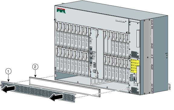
Figure 6-15 Removing the Bezel and Air Filter

1

Protective bezel

2

Air filter


6.3.3 Cleaning or Replacing the Air Filter

This section describes how to clean or replace a Cisco 6160 air filter.


Step 1 Use one of the following methods to clean the air filter:

Vacuum the filter until it is clean and free of dust. This method is preferred because you need not dry the filter afterwards.

Wash the filter by holding it under a stream of plain water. Supporting the filter with your fingers, hold the filter under the water with the metal grill facing up and let the water flow down through the filter. (This orientation causes the water to flow through the filter in the direction opposite from the usual air flow, so you dislodge rather than embed matter trapped in the filter.) Allow the filter to dry thoroughly before reinstalling it.

If the filter is extremely dirty, immerse the filter in a solution of hot water and mild detergent. Rinse the filter thoroughly in clear water and allow it to dry completely before reinstalling it.

Step 2 To replace the clean filter or to install a new one, hold the filter so that the side with the metal grill is facing the chassis.

Step 3 Insert the filter into its slot at the bottom of the chassis.

Step 4 Replace the bezel that covers the air filter and use a screwdriver to tighten the captive screws to secure the bezel.


hometocprevnextglossaryfeedbacksearchhelp

Posted: Thu Feb 24 14:57:58 PST 2005
All contents are Copyright © 1992--2005 Cisco Systems, Inc. All rights reserved.
Important Notices and Privacy Statement.