cc/td/doc/product/dsl_prod/6160
hometocprevnextglossaryfeedbacksearchhelp
PDF

Table Of Contents

Product Overview

1.1 Introduction to the Cisco 6160 System

1.1.1 Features

1.1.2 Configurations

1.2 Cisco 6160 Chassis Overview

1.2.1 Backplane

1.2.2 Chassis Card Compartment

1.2.3 Line Cards

1.2.4 NI-2 Cards

1.2.5 I/O Cards

1.2.6 PEM

1.2.7 Blower Tray

1.2.8 Air Filter

1.3 Management Software


Product Overview


This chapter provides an overview of the Cisco 6160 digital subscriber line (DSL) access multiplexer (DSLAM) and its related components, collectively known as the Cisco 6160 system. This chapter contains the following sections:

Introduction to the Cisco 6160 System

Cisco 6160 Chassis Overview

Management Software

1.1 Introduction to the Cisco 6160 System

The Cisco 6160 system is part of the Cisco DSL product family that provides end-to-end service by carrying voice or data traffic, or both, between a subscriber's home or office, a central office (CO), and various networks beyond. The Cisco 6160 system sends and receives subscriber data (often Internet service) over existing copper telephone lines, concentrating all traffic onto a single high-speed trunk for transport to the Internet or a corporate intranet. Data is modulated by xDSL customer premises equipment (CPE) devices, which are connected to PCs or routers at the subscriber site. The data then travels over telephone lines to the Cisco 6160 system at the CO.


Note For detailed information on the various components in the Cisco DSL product family (including CO and CPE devices), see the "Related Documentation" section on page xvii.


The Cisco 6160 system uses asymmetric digital subscriber line (ADSL), ISDN digital subscriber line (IDSL), symmetrical digital subscriber line (SDSL), and single-pair high-speed digital subscriber line (SHDSL, also known as G.SHDSL), collectively known as xDSL, technologies to support up to 256 subscribers connected either directly to the chassis or through a plain old telephone service (POTS) splitter. Filters separate voice and data signals when subscribers are connected to the Cisco 6160 DSLAM through a POTS splitter chassis. Cables connected to the POTS splitter route digital data signals to line cards in the Cisco 6160 chassis and voice signals to the CO facility switching network.

The Cisco 6160 system includes the following hardware and software components:

Cisco 6160 chassis. The following components will be installed in or on the chassis:

xDSL Transmission Unit—central office line cards (xTU-Cs)—quad-port flexi ATU-C line cards (4xflexis), quad-port STU-C line cards (4xSDSLs), octal-port DMT ATU-C line cards (8xDMTs), octal-port single-pair high-speed digital subscriber line, also known as symmetric high bit rate digital subscriber loop (G.SHDSL) line cards (8xG.SHDSLs), and octal-port ITU-C line cards (8xISDLs).


Note For line card intermixing information, see the "Line Card Intermixing" section.


Second generation network interface (NI-2) cards—DS3+T1/E1 IMA, DS3/2DS3, OC-3c/2DS3, or OC-3c/OC-3c.

Input/output (I/O) cards—DS3/2DS3+8xT1 IMA or DS3/2DS3 (I/O cards are located on the chassis backplane).

Power entry modules (PEMs), which distribute power throughout the chassis.

Blower tray.

Air filter.

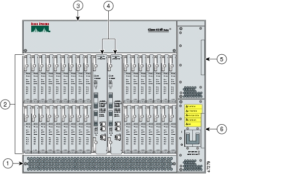
Figure 1-1 shows the location of the Cisco 6160 chassis components.

Figure 1-1 Cisco 6160 Chassis Components

1

Air filter

4

NI-2 card (primary and secondary)

2

xTU-C line cards (slots 1 to 9 and 12 through 34)

5

Secondary PEM

3

Blower tray

6

Primary PEM


POTS splitters (optional). The POTS splitter is a passive device that supports simultaneous voice (basic telephone service) and data services.


Note POTS splitters are available from Cisco Ecosystem partners. Please verify the compatibility with your Cisco representative.

For POTS splitter information, refer to the vendor documentation.


Management software—Provisions and manages the Cisco 6160 system.

Cisco IOS—A command-line interface (CLI) that is available for network element provisioning.

Cisco DSL Manager (CDM)—An element management system designed to configure and manage the 6xxx series of Cisco IOS software-based DSLAMs through a graphical-user interface (GUI). CDM provides the following areas of network management: fault, configuration, performance, and security. CDM runs within the Cisco Element Manager Framework (EMF); both are installed on Sun workstations.

Cisco EMF is based on an object model in which network elements or modules represent the managed entity. Each object is defined by a class and specific attributes. An object can represent a network element or a more abstract entity such as a link relationship, a network, or a container such as a site, shelf, or region.


Note See the "Hardware Specifications" section on page A-1 for minimum software and network management release requirements per Cisco 6160 chassis component.


1.1.1 Features

The Cisco 6160 system includes the following features:

Supports ADSL, IDSL, SDSL, and SHDSL.

Carrierless amplitude and phase modulation (CAP) rate adaptive DSL (RADSL), ANSI T1.413 Discrete Multitone (DMT), G.DMT, G.SHDSL, and G.lite modem support.

Terminates up to 256 ADSL, 256 IDSL, 128 SDSL, or 256 SHDSL subscriber lines.

Network Equipment Building System (NEBS) compliant, 23-inch chassis.

Network transmission connections.

DS3.

OC-3c.

T1.

T1 inverse multiplexing over ATM (IMA).

Manageable through Cisco IOS or CDM.

Subtending—Up to 13 Cisco 6160 chassis can be linked together (subtended) so that they are served by a single network trunk port, which supports up to 3328 xDSL subscribers.

Building integrated timing supply (BITS) clock input.

Facility alarm input.

Supports the entire range of virtual channel identifier (VCI)/virtual path identifier (VPI) connections, and connections are not limited by memory.

ATM Forum User-Network Interface (UNI) Versions 3.1/4.0 compliant.

Nonblocking ATM switching architecture.

Allows up to four ATM classes of service simultaneously.

1.1.2 Configurations

This guide details the installation steps for the following configurations:

Cisco 6160 with a POTS splitter

Cisco 6160 without a POTS splitter

IMA

Subtended network

1.1.2.1 Cisco 6160 with a POTS Splitter Configuration

The Cisco 6160 with a POTS splitter configuration supports up to 256 data subscribers through directly connected modems using xDSL technology. To increase subscribership, you can add additional chassis to your system.

This configuration can include the following hardware components:

Cisco 6160 chassis

8xIDSLs

8xDMTs (configure as DMT or G.lite)

4xflexis (configure as CAP, DMT, or G.lite)

DS3/2DS3, DS3+T1/E1 IMA, OC-3c/2DS3, or OC-3c/OC-3c NI-2 card(s)

DS3/2DS3+8xT1 IMA I/O card or DS3/2DS3 I/O card or

PEM(s)

Blower tray

Third-party POTS splitter—Installed directly below the Cisco 6160 chassis

1.1.2.2 Cisco 6160 Without a POTS Splitter Configuration

The Cisco 6160 without a POTS splitter configuration supports up to 256 data subscribers through directly connected modems using xDSL technology. To increase subscribership, you can add additional chassis to your system.

This configuration can include the following hardware components:

Cisco 6160 chassis

8xIDSLs

8xG.SHDSLs

8xDMTs (configure as DMT or G.lite)

4xSDSLs

4xflexis (configure as CAP, DMT, or G.lite)

DS3/2DS3, DS3+T1/E1 IMA, OC-3c/2DS3, or OC-3c/OC-3c NI-2 card(s)

DS3/2DS3+8xT1 IMA I/O card or DS3/2DS3 I/O card

PEM(s)

Blower tray

1.1.2.3 IMA Configuration

The DS3+T1/E1 IMA NI-2 card uses IMA technology to aggregate multiple low-speed links into one larger virtual trunk or IMA group. An inverse multiplexer appears to your ATM switch router as one logical pipe. IMA provides you with modular bandwidth to access the ATM network between T1 and DS3 rates. The Cisco 6160 allows you to combine up to eight T1 lines to form an IMA group.

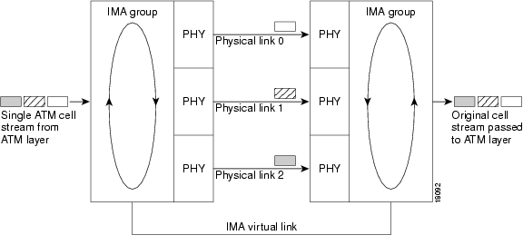
IMA breaks up the ATM cell stream, distributes the cells over the multiple physical links of an IMA group, then recombines the cells into a single stream at the other end of the connection. The ATM cells are distributed in a round-robin fashion over the physical links of the IMA group, recombined at the receiving IMA group, and passed in their original form to the ATM layer (see Figure 1-2). Using the multiple links of an IMA group increases the logical link bandwidth to approximately the sum of the individual link rates. The physical links should be nominally the same length to avoid excessive intragroup delay. We recommend that all of the links in an IMA group be bundled together between the source and the destination.

Figure 1-2 Inverse Multiplexing and Recombining of ATM Cells Through IMA Groups

The DS3/2DS3+8xT1 IMA I/O cards have eight ports. You can use the eight ports on the DS3/2DS3+8xT1 IMA I/O cards as independent ATM links or in the IMA mode. The following bullets are examples of possible IMA groups, independent ATM links, and mixed modes. In examples of IMA groups, two links are assumed per group.

Four IMA groups with any combination of eight links

Three IMA groups and up to two independent ATM links

Two IMA groups and up to four independent ATM links

One IMA group and up to six independent ATM links

No IMA group and up to eight independent ATM links

The T1 (1.544 Mbps) IMA port adapters provide trunk or subtend connectivity and are used for intercampus or wide-area links. The T1 IMA port adapters support unshielded twisted-pair (UTP) connectors. The order of assignment of links to an IMA group is not restricted.

The IMA group interfaces use a naming convention different from those used by the other interfaces in the system. IMA group interfaces are named with the convention atm<slot>/ima<group>, where <slot> is the slot number for the DS3+T1/E1 IMA NI-2 card and <group> is the IMA group number from 0 to 3. Table 1-1 lists the interface naming conventions.

Table 1-1 Interface Naming Conventions 

Interface
Name

DS3 link

atm0/1

T1/E1 link 0

atm0/2

T1/E1 link 1

atm0/3

T1/E1 link 2

atm0/4

T1/E1 link 3

atm0/5

T1/E1 link 4

atm0/6

T1/E1 link 5

atm0/7

T1/E1 link 6

atm0/8

T1/E1 link 7

atm0/9

IMA group 0

atm0/ima0

IMA group 1

atm0/ima1

IMA group 2

atm0/ima2

IMA group 3

atm0/ima3


1.1.2.4 Subtended Network Configuration

A subtended network configuration

Services and aggregates the data from one or more Cisco 6160 chassis into a subtending host system to take advantage of the data network interface on the subtending host chassis.

Reduces the number of ATM edge-switch ports that are required to terminate the system.

Supports a Cisco 6160 with a POTS splitter configuration and a Cisco 6160 without a POTS splitter configuration.

The term subtending refers to the host chassis, and subtended refers to the downstream chassis in a subtended network.


Note For information on enabling redundancy in subtended network configurations, see the "Redundancy in Subtended Configurations" section.


A subtended network configuration supports the following features:

Four arbitration priorities, one for each quality of service (QoS) level. The supported QoS service levels are

Constant bit rate (CBR) for rate-limited services that require guaranteed bandwidth and bounded delay

Variable bit rate real time (VBR-rt) for delay-sensitive voice and video services

Variable bit rate non real time (VBR-nrt) for high-priority data services

Unspecified bit rate (UBR) for low-priority data services

Explicit forward congestion indication (EFCI) marking for available bit rate (ABR) service support.

Guaranteed frame rate (GFR).

Tree or daisy chain topology configurations for DS3 subtended Cisco 6160 chassis.

Daisy chain topology configurations for OC-3c subtended Cisco 6160 chassis.

Star topology configurations for T1 or T1 IMA group subtended Cisco 6160 chassis.

Fair access to the trunk port for each subtended chassis.

A network trunk port that operates as fast as any subtended link.

The NI-2 card provides one of the following types of subtended network connections:

A high-speed OC-3c optical ATM interface that supports single-mode fiber (SMF) intermediate range

A high-speed OC-3c optical ATM interface that supports multimode fiber (MMF) short range

Up to eight T1 interfaces when you are using the DS3+T1/E1 IMA NI-2 card in conjunction with the DS3/2DS3+8xT1 IMA I/O card.

Up to four IMA interfaces when you are using the DS3+T1/E1 IMA NI-2 card in conjunction with the DS3/2DS3+8xT1 IMA I/O card.


Note The use of a T1 or T1 IMA group trunk disables the DS3 interface.


The following sections detail the different types of subtended network configurations:

Subtended Network Configuration with DS3+T1/E1 IMA NI-2 Cards

Subtended Network Configuration with DS3/2DS3 or OC-3c/2DS3 NI-2 Cards

Subtended Network Configuration with OC-3c/OC-3c NI-2 Cards

1.1.2.4.1 Subtended Network Configuration with DS3+T1/E1 IMA NI-2 Cards

In a subtended network configuration using DS3+T1/E1 IMA NI-2 cards, you can subtend Cisco 6160 systems with the following network configurations:

A DS3 trunk with

Up to eight individual T1 subtended interfaces, or

Up to four IMA groups, or

A combination of the two

Eight T1 links which can be used as trunk or subtend interfaces or be combined into trunk or subtend T1 IMA groups.

A T1 IMA group or T1 UNI as the trunk, or

Up to seven individual T1 interfaces or up to four T1 IMA groups, or

A combination of the two


Note The use of a T1 or T1 IMA group trunk disables the DS3 interface.


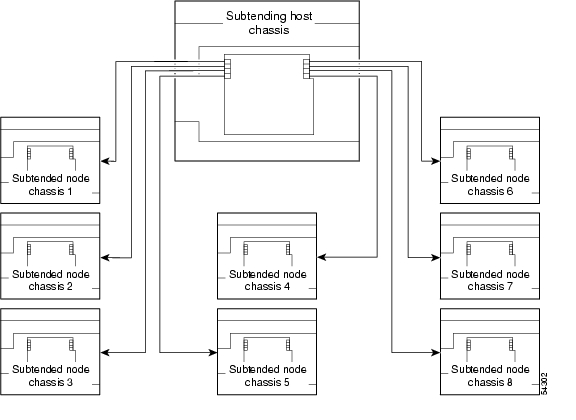
Figure 1-3 shows an example of a subtended network with a star topology. The subtending host chassis in the middle of the star topology connects directly to the ATM switch. With a DS3 trunk, you can have up to eight subtended node chassis connected to the subtending host chassis.

Figure 1-3 Subtended Network Configuration Using DS3+T1/E1 IMA NI-2 Cards


Note Consult with your network architect or Cisco customer service representative for examples of other subtending topology configurations.


1.1.2.4.2 Subtended Network Configuration with DS3/2DS3 or OC-3c/2DS3 NI-2 Cards

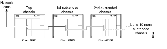
In a subtended network configuration using DS3/2DS3 or OC-3c/2DS3 NI-2 cards, you can subtend a Cisco 6160 chassis to four tiers, with up to 12 subtended node chassis, all connecting through one subtending host chassis to the ATM backbone.

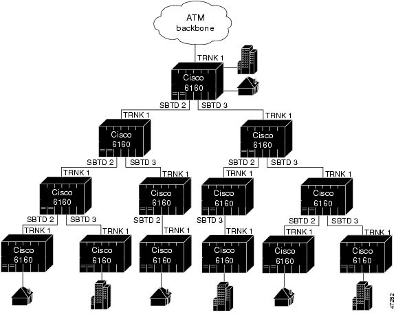
Figure 1-4 shows DS3-configured Cisco 6160 systems subtended in a combined subtending tree topology with daisy chain. The subtending host chassis at the top of the subtending tree connects directly to the ATM switch. The middle two Cisco 6160 chassis in the lowest level are daisy chained. TRNK 1 refers to the network trunk or the Cisco 6160 chassis subtended network interface. SBTD 2 and SBTD 3 refer to the two Cisco 6160 chassis subtended interfaces. You make network interface connections at the I/O card, which is installed on the Cisco 6160 chassis backplane.

Figure 1-4 Subtended Network Configuration Using DS3/2DS3 or OC-3c/2DS3 NI-2 Cards

For each chassis in a subtended network configuration to have fair access to the shared trunk, the chassis must have a unique ID number. The subtending host chassis places this ID number in the GFC field of the ATM header of each cell; this ID number is then used to forward cells up the tree to the network trunk.


Note You can subtend Cisco 6160 chassis with DS3/2DS3 or OC-3c/2DS3 NI-2 cards in a continuous daisy chain. However, a daisy-chained subtending topology is not optimal for data throughput for a Cisco 6160 chassis that uses DS3/2DS3 or OC-3c/2DS3 NI-2 cards.


Cisco IOS software does not manage the primary Cisco 6160 chassis and all subtended Cisco 6160 chassis as a single large Cisco 6160 system. Each Cisco 6160 chassis supports an independent Cisco IOS processor and MIBs.

1.1.2.4.3 Subtended Network Configuration with OC-3c/OC-3c NI-2 Cards

In a subtended network configuration using OC-3c/OC-3c NI-2 cards (SMF or MMF), you can subtend up to 12 OC-3c configured subtended node chassis in a daisy chain, all connecting through one subtending host chassis to the ATM backbone (see Figure 1-5).

Figure 1-5 Subtended Network Configuration Using OC-3c/OC-3c NI-2 Cards

1.2 Cisco 6160 Chassis Overview

The Cisco 6160 system consists of circuitry and connections that reside within a chassis, an enclosure that allows modular insertion and removal of various field-replaceable units (FRUs).


Note For hardware specifications for the Cisco 6160 chassis, see the "Cisco 6160 System Hardware Specifications" section on page A-2.


The following sections detail these Cisco 6160 hardware components:

Backplane

Chassis Card Compartment

Line Cards

NI-2 Cards

I/O Cards

PEM

Blower Tray

Air Filter

1.2.1 Backplane

Located on the back of the Cisco 6160 chassis, the backplane provides the following services:

Interconnects the NI-2 card(s), I/O card, and line cards

Connects the line cards with the subscriber connectors

Distributes power, clocking, and other common signals to all the components

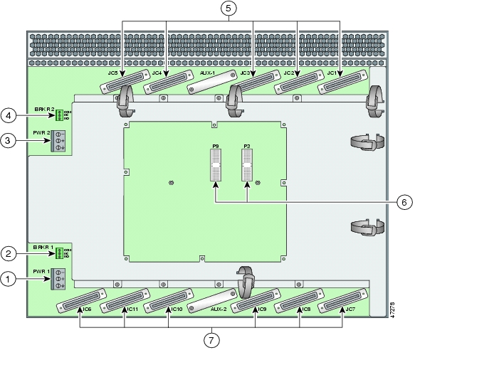
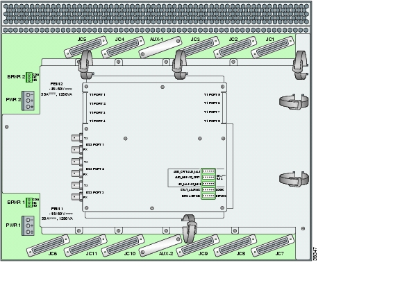
Figure 1-6 shows the Cisco 6160 backplane.

Figure 1-6 Cisco 6160 Backplane

1

PWR 1—Power terminal block connector.

5

Connectors JC1 through JC5.

2

BRKR 1—A terminal block connector used to wire alarm relays to external alarms.

6

I/O card connectors (P3 and P9)—Two 2-mm HM1 modular connectors (male on the Cisco 6160 and female on the I/O card) are used to connect the I/O card.

3

PWR 2—Power terminal block connector. Use if a secondary (redundant) PEM is installed.

7

Connectors JC6 through JC11.

4

BRKR 2—A terminal block connector used to wire alarm relays to external alarms. Use if a secondary (redundant) PEM is installed.


1 HM = hard metric


The power terminal block connectors (PWR 1 and PWR 2) are equipped with a positive, negative, and ground receptacle. This connector receives the power connections from the external power source.

The breaker terminal block connectors (BRKR 1 and BRKR 2) are equipped with three contacts (common [CO], normally closed [NC], and normally open [NO]) that used to wire alarm relays to external alarms.

There are eleven 50-pin Champ connectors used to transfer data between the Cisco 6160 and the POTS splitter in a Cisco 6160 with POTS splitter configuration. In a Cisco 6160 without a POTS splitter configuration, the connectors are used to transfer data between the Cisco 6160 and the CPE equipment. Table 1-2 describes the Champ connectors and the corresponding slots in the Cisco 6160 chassis.

Table 1-2 Cisco 6160 Backplane Connectors and Slots

Champ Connector
Cisco 6160 Chassis Slots

JC1

Slots 1 to 3

JC2

Slots 4 to 6

JC3

Slots 7 to 9

JC4

Slots 12 to 14

JC5

Slots 15 to 17

JC6

Slots 18 and 34

JC7

Slots 19 to 21

JC8

Slots 22 to 24

JC9

Slots 25 to 27

JC10

Slots 28 to 30

JC11

Slots 31 to 33


1.2.2 Chassis Card Compartment

As shown in Figure 1-7, the Cisco 6160 card compartment houses

32 slots for line cards

2 slots for NI-2 cards

2 compartments for PEMs

1 compartment for a blower tray

1 compartment for an air filter

Figure 1-7 Cisco 6160 Chassis Compartments

1

Air filter

4

NI-2 card (primary and secondary)

2

xTU-C line cards (slots 1 to 9 and 12 through 34)

5

Secondary PEM

3

Blower tray

6

Primary PEM


The Cisco 6160 chassis has 34 slots that hold line cards and NI-2 cards. Each card slot on a chassis is numbered along the top of the chassis. In this guide, the slot numbers are shown on the cards for easy reference and readability. These slots are referred to in subsequent sections of this chapter and elsewhere in this guide. Table 1-3 describes each card slot assignment for the Cisco 6160 chassis.

Table 1-3 Cisco 6160 Card Slot Assignments 

Card Slot
Card Assignment

1 to 9

4xflexis, 4xSDSLs1 , 8xDMTs, 8xG.SHDSLs1, or 8xIDSLs

10

NI-2 card

11

Secondary (redundant) NI-2 card

12 to 34

4xflexis, 4xSDSLs, 8xDMTs, 8xG.SHDSLs, or 8xIDSLs

1 4xSDSLs and G.SHDSLs can be used only in a Cisco 6160 without a POTS splitter configuration.


Note For line card intermixing information, see the "Line Card Intermixing" section


1.2.3 Line Cards

The following sections provide details about the Cisco 6160 line cards.

8xIDSL Overview

8xG.SHDSL Overview

8xDMT Overview

4xSDSL Overview

4xflexi Overview

Line Card Intermixing

1.2.3.1 8xIDSL Overview

The 8xIDSL

Supports 2B1Q line encoding.

Supports eight IDSL modem connections, or four connections when the chassis limits the number of tip and ring connectors.

Supports configured data rates (56 kbps, 64 kbps, 128 kbps, and 144 kbps).

Supports multiple Frame Relay and PPP encapsulations.

Provides a DCE interface.

The Cisco 6160 chassis can include up to 32 8xIDSLs for a total of 256 IDSL modem connections.


Note For hardware specifications for the 8xIDSL, see the "8xIDSL Specifications" section on page A-3.

For line card intermixing information, see the "Line Card Intermixing" section.


Figure 1-8 shows a close-up of the 8xIDSL faceplate.

Figure 1-8 8xIDSL Faceplate

1

Ejector lever

4

ACTIVE LED

2

Locking tab

5

Modem port status LEDs

3

STATUS LED

6

Extraction tab


Table 1-4 describes LEDs on the 8xIDSL.

Table 1-4 8xIDSL LEDs 

LED
State
Function

STATUS

Green slow blinking

No errors, but no connection established.

Green fast blinking

The image download is in progress.

Green solid

NI-2 communication established.

Red

The self-test or line card has failed.

Off

The ITU-C line card has a power failure.

ACTIVE

Green solid

The line card is activated.

Off

The line card is not in service.

ITU-C 1

Green solid

Modem 1 is trained.

Green blinking

Training is in progress for modem 1.

Off

Modem 1 is idle.

ITU-C 2

Green solid

Modem 2 is trained.

Green blinking

Training is in progress for modem 2.

Off

Modem 2 is idle.

ITU-C 3

Green solid

Modem 3 is trained.

Green blinking

Training is in progress for modem 3.

Off

Modem 3 is idle.

ITU-C 4

Green solid

Modem 4 is trained.

Green blinking

Training is in progress for modem 4.

Off

Modem 4 is idle.

ITU-C 5

Green solid

Modem 5 is trained.

Green blinking

Training is in progress for modem 5.

Off

Modem 5 is idle.

ITU-C 6

Green solid

Modem 6 is trained.

Green blinking

Training is in progress for modem 6.

Off

Modem 6 is idle.

ITU-C 7

Green solid

Modem 7 is trained.

Green blinking

Training is in progress for modem 7.

Off

Modem 7 is idle.

ITU-C 8

Green solid

Modem 8 is trained.

Green blinking

Training is in progress for modem 8.

Off

Modem 8 is idle.


1.2.3.2 8xG.SHDSL Overview

The 8xG.SHDSL

Supports eight G.SHDSL modem connections.

Supports trellis coded pulse amplitude modulation (TC-PAM) line encoding.

Converts G.SHDSL modulation from the line into digital data streams to and from the NI-2 card.

Supports fixed and adaptive rate modes

Has deployment guidelines when used in the Cisco 6160 system, see Figure 1-13.


Note For hardware specifications for the 8xG.SHDSL, see the "8xG.SHDSL Specifications" section on page A-4.

For line card intermixing information, see the "Line Card Intermixing" section.


Figure 1-9 shows a close-up of the 8xG.SHDSL faceplate.

Figure 1-9 8xG.SHDSL Faceplate

1

Ejector lever

4

ACTIVE LED

2

Locking tab

5

Modem port status LEDs

3

STATUS LED

6

Extraction tab


Table 1-5 describes LEDs on the 8xG.SHDSL.

Table 1-5 8xG.SHDSL LEDs 

LED
State
Function

STATUS

Green slow blinking

No errors, but no connection established.

Green fast blinking

The image download is in progress.

Green solid

NI-2 communication established.

Red

The self-test or line card has failed.

Off

The SHTU-C line card has a power failure.

ACTIVE

Green solid

The line card is activated.

Off

The line card is not in service.

SHTU-C1

Green solid

Modem 1 is trained.

Green blinking

Training is in progress for modem 1.

Off

Modem 1 is idle.

SHTU-C2

Green solid

Modem 2 is trained.

Green blinking

Training is in progress for modem 2.

Off

Modem 2 is idle.

SHTU-C3

Green solid

Modem 3 is trained.

Green blinking

Training is in progress for modem 3.

Off

Modem 3 is idle.

SHTU-C4

Green solid

Modem 4 is trained.

Green blinking

Training is in progress for modem 4.

Off

Modem 4 is idle.

SHTU-C5

Green solid

Modem 5 is trained.

Green blinking

Training is in progress for modem 5.

Off

Modem 5 is idle.

SHTU-C6

Green solid

Modem 6 is trained.

Green blinking

Training is in progress for modem 6.

Off

Modem 6 is idle.

SHTU-C7

Green solid

Modem 7 is trained.

Green blinking

Training is in progress for modem 7.

Off

Modem 7 is idle.

SHTU-C8

Green solid

Modem 8 is trained.

Green blinking

Training is in progress for modem 8.

Off

Modem 8 is idle.


1.2.3.3 8xDMT Overview

The 8xDMT

Supports eight ADSL modem connections.

Converts ADSL modulation from the line into digital data streams to and from the NI-2 card.

Negotiates the line rate with the CPE when it trains and bases the rate on line quality and distance.

If provisioned, the 8xDMT rate adapts to the maximum bit rate negotiable on the line. The maximum bit rate settings are provisioned in the management software.

The chassis can include up to 32 8xDMTs for a total of 256 ADSL modem connections.


Note For hardware specifications for the 8xDMT, see the "8xDMT Specifications" section on page A-5.

For line card intermixing information, see the "Line Card Intermixing" section.


Figure 1-10 shows a close-up of the 8xDMT faceplate.

Figure 1-10 8xDMT Faceplate

1

Ejector lever

4

ACTIVE LED

2

Locking tab

5

Modem port status LEDs

3

STATUS LED

6

Extraction tab


Table 1-6 describes LEDs on the 8xDMT.

Table 1-6 8xDMT LEDs 

LED
State
Function

STATUS

Green slow blinking

No errors, but no connection established.

Green fast blinking

The image download is in progress.

Green solid

NI-2 communication established.

Red

The self-test or line card has failed.

Off

The ATU-C line card has a power failure.

ACTIVE

Green solid

The line card is activated.

Off

The line card is not in service.

ATU-C 1

Green solid

Modem 1 is trained.

Green blinking

Training is in progress for modem 1.

Off

Modem 1 is idle.

ATU-C 2

Green solid

Modem 2 is trained.

Green blinking

Training is in progress for modem 2.

Off

Modem 2 is idle.

ATU-C 3

Green solid

Modem 3 is trained.

Green blinking

Training is in progress for modem 3.

Off

Modem 3 is idle.

ATU-C 4

Green solid

Modem 4 is trained.

Green blinking

Training is in progress for modem 4.

Off

Modem 4 is idle.

ATU-C 5

Green solid

Modem 5 is trained.

Green blinking

Training is in progress for modem 5.

Off

Modem 5 is idle.

ATU-C 6

Green solid

Modem 6 is trained.

Green blinking

Training is in progress for modem 6.

Off

Modem 6 is idle.

ATU-C 7

Green solid

Modem 7 is trained.

Green blinking

Training is in progress for modem 7.

Off

Modem 7 is idle.

ATU-C 8

Green solid

Modem 8 is trained.

Green blinking

Training is in progress for modem 8.

Off

Modem 8 is idle.


1.2.3.4 4xSDSL Overview

The 4xSDSL

Supports four SDSL modem connections.

Supports 2B1Q line encoding.

Transports ATM data at rates of up to 1168 kbps over a single twisted pair of copper wire.

Converts SDSL modulation from the line into digital data streams to and from the NI-2 card.

The negotiated bit rate is the lower of the following rates:

Provisioned bit rate set for the 4xSDSL in the management software

Assigned bit rate at the CPE

The chassis can include up to 32 4xSDSLs for a total of 128 SDSL modem connections.


Note For hardware specifications for the 4xSDSL, see the "4xSDSL Specifications" section on page A-6.

For line card intermixing information, see the "Line Card Intermixing" section.


The edge connector key, located on the rear of the 4xSDSL, connects the 4xSDSL to the backplane of the chassis. Two edge connector keys are available for the 4xSDSL: one has six notches and one has seven notches. You can only install the edge connector key with seven notches in the Cisco 6160.

Figure 1-11 shows a close-up of the 4xSDSL faceplate.

Figure 1-11 4xSDSL Faceplate

1

Ejector lever

4

ACTIVE LED

2

Locking tab

5

Modem port status LEDs

3

STATUS LED

6

Extraction tab


Table 1-7 describes the LEDs on the 4xSDSL.

Table 1-7 4xSDSL LEDs 

LED
State
Function

STATUS

Green slow blinking

No errors, but no connection established.

Green fast blinking

The image download is in progress.

Green solid

NI-2 communication established.

Red

The self-test or line card has failed.

Off

The STU-C line card has a power failure.

ACTIVE

Green solid

The line card is activated.

Off

The line card is not in service.

STU-C 1

Green solid

Modem 1 is trained.

Green blinking

Training is in progress for modem 1.

Off

Modem 1 is idle.

STU-C 2

Green solid

Modem 2 is trained.

Green blinking

Training is in progress for modem 2.

Off

Modem 2 is idle.

STU-C 3

Green solid

Modem 3 is trained.

Green blinking

Training is in progress for modem 3.

Off

Modem 3 is idle.

STU-C 4

Green solid

Modem 4 is trained.

Green blinking

Training is in progress for modem 4.

Off

Modem 4 is idle.


1.2.3.5 4xflexi Overview

The 4xflexi

Supports four ADSL modem connections.

Supports CAP, DMT, or G.lite line encoding.

Converts ADSL modulation from the line into digital data streams to and from the NI-2 card.

Negotiates the line rate with the CPE when it trains and bases the rate on line quality and distance.

If provisioned, the 4xflexi rate adapts to the maximum bit rate negotiable on the line. The maximum bit rate settings are provisioned in the management software.


Note For hardware specifications for the 4xflexi, see the "4xflexi Specifications" section on page A-6.

For line card intermixing information, see the "Line Card Intermixing" section.


The Cisco 6160 chassis can include up to 32 4xflexis for a total of 128 ADSL modem connections.

The edge connector key, located on the rear of the 4xflexi, connects the 4xflexi to the backplane of the chassis. Two edge connector keys are available for the 4xflexi: one has six notches and one has seven notches. You can only install the edge connector key with seven notches in the Cisco 6160.

Figure 1-12 shows a close-up of the 4xflexi faceplate.

Figure 1-12 4xflexi Faceplate

1

Ejector lever

5

Line card mode LEDs

2

Locking tab

6

Modem port status LEDs

3

STATUS LED

7

Extraction tab

4

ACTIVE LED


Table 1-8 describes the LEDs on the 4xflexi.

Table 1-8 4xflexi LEDs 

LED
State
Function

STATUS

Green slow blinking

No errors, but no connection established.

Green fast blinking

The image download is in progress.

Green solid

NI-2 communication established.

Red

The self-test or line card has failed.

Off

The ATU-C line card has a power failure.

ACTIVE

Green solid

The line card is activated.

Off

The line card is not in service.

CAP

Green solid

The line card is in CAP mode.

Off

The line card is not in CAP mode.

DMT

Green solid

The line card is in DMT mode.

Off

The line card is not in DMT mode.

G.LITE

Green solid

The line card is in G.lite mode.

Off

The line card is not in G.lite mode.

A1

Green solid

Modem 1 is trained.

Green blinking

Training is in progress for modem 1.

Off

Modem 1 is idle.

A2

Green solid

Modem 2 is trained.

Green blinking

Training is in progress for modem 2.

Off

Modem 2 is idle.

A3

Green solid

Modem 3 is trained.

Green blinking

Training is in progress for modem 3.

Off

Modem 3 is idle.

A4

Green solid

Modem 4 is trained.

Green blinking

Training is in progress for modem 4.

Off

Modem 4 is idle.


1.2.3.6 Line Card Intermixing

The Cisco 6160 chassis supports line card intermixing. The following sections will use the terms halves and quadrants. The Cisco 6160 chassis consists of two halves

First half—Slots 1 to 9 and slots 19 to 27

Second half—Slots 12 to 18 and slots 28 to 34

The Cisco 6160 chassis consists of four quadrants

Quadrant 1—Slots 1 to 9

Quadrant 2—Slots 12 to 18

Quadrant 3—Slots 19 to 27

Quadrant 4—Slots 28 to 34

The following sections detail the line card intermixing guidelines for the Cisco 6160.

1.2.3.6.1 Guidelines for Intermixing xDSL Line Cards

Mixing line cards of different modulation types in the same quadrant of any Cisco DSLAM is prohibited. Different modulation types are allowed in the same half of a chassis with the exceptions of slots 18 and 34 in the Cisco 6160 beginning with Cisco IOS release 12.2(7)DA. Mixing line cards of the same modulation type (for example, 4xFlexiDMT and 8xDMT line cards) in a quadrant is allowed.


Note For 8xG.SHDSL-specific intermixing guidelines, see either the "Guidelines for Intermixing 8xG.SHDSLs—Cisco IOS Release 12.1(7)DA2, 12.2(1b)DA, and 12.2(5)DA" section or "Guidelines for Intermixing 8xG.SHDSLs—Cisco IOS Release 12.1(7)DA2, 12.2(1b)DA, and 12.2(5)DA" section.


1.2.3.6.2 Guidelines for Intermixing 8xG.SHDSLs—Cisco IOS Release 12.1(7)DA2, 12.2(1b)DA, and 12.2(5)DA

The Cisco 6160 chassis can be fully populated with 8xG.SHDSLs while retaining QoS, as long as the upstream bandwidth is provisioned at a maximum of 5 Mbps for even ports and a maximum of 5 Mbps for odd ports per line card. Once an 8xG.SHDSL is installed in a chassis quadrant, no ADSL line cards can be installed in that same quadrant.


Note Due to spectral compatibility limitations in the right side configuration of the Cisco 6160 chassis, line card slots 18 and 34 should be configured as specified in Table 1-9.


1.2.3.6.3 Guidelines for Intermixing 8xG.SHDSLs—Cisco IOS Release 12.2(7)DA and Later

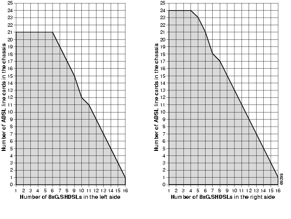
The Cisco 6160 chassis supports up to 16 8xG.SHDSLs installed per chassis while retaining QoS. Once an 8xG.SHDSL is installed in a quadrant, no ADSL line cards can be installed in that same quadrant.

Figure 1-13 illustrates the optimal deployment of 8xG.SHDSLs and quadrant intermixing of ADSL line cards in the Cisco 6160 chassis. For example

If 4 8xG.SHDSLs are installed in the left side of the chassis, only 25 ADSL line cards can be installed in the remaining quadrants.

If 4 8xG.SHDSLs are installed in the right side of the chassis, only 23 ADSL line cards can be installed in the remaining chassis quadrants.


Note Random cell loss may occur if the guidelines for 8xG.SHDSL deployment in a system are exceeded.


Figure 1-13 8xG.SHDSL and ADSL Line Card Intermixing in the Cisco 6160 Chassis

1.2.3.6.4 Guidelines for Intermixing 8xG.SHDSLs—Cisco IOS Release 12.2(12)DA and Later for NI2-155SM-155SM2 or NI2-155MM-155MM2 Only

This section describes intermixing in Cisco IOS Release 12.2(12)DA and later for NI2-155SM-155SM2 or NI2-155MM-155MM2 only. All other NI2s, including NI2-155SM-155SM and NI2-155MM-155MM, follow guidelines as described in the "Guidelines for Intermixing 8xG.SHDSLs—Cisco IOS Release 12.2(7)DA and Later" section.

The Cisco 6015, Cisco 6160, and Cisco 6260 can be fully populated with 8xG.SHDSLs while retaining QoS.

In the Cisco 6160 and Cisco 6260, once an 8xG.SHDSL is installed in a chassis quadrant, no other type of line card can be installed in that same quadrant.

In the Cisco 6015, intermixing is limited to chassis halves.


Note In order to provision 18.5 Mbps per line card in a chassis fully populated with 8xG.SHDSLs, an OC-3c/OC-3c single-mode fiber (SMF) or multi-mode fiber (MMF) NI-2 card (NI2-155SM-155SM2 and NI2-155MM-155MM2) must be installed in the chassis.


Due to spectral compatibility limitations in the right side configuration of the Cisco 6160 chassis, line card slots 18 and 34 should be configured as specified in Table 1-9.

Table 1-9 Cisco 6160 Right Side Configuration Guidelines 

Slot 18
Slot 34
Configuration

8xG.SHDSL

8xG.SHDSL

Supported

8xG.SHDSL

ADSL

Not supported

8xG.SHDSL

Empty

Supported

ADSL

ADSL

Not supported

ADSL

8xG.SHDSL

Not supported

ADSL

Empty

Supported


1.2.4 NI-2 Cards

The NI-2 card is a system processor module that includes the following features:

Connects to the xTU-C line cards through point-to-point serial data buses on the backplane.

Contains the ATM switch fabric.

Supports subtending of as many as 12 subtended node chassis. See the "Subtended Network Configuration" section for detailed information about subtending.

Provides visual and audible operating status alerts.

Provides CO facility alarm relay contact interfaces and an alarm cut-off (ACO) button.

Is manageable through Cisco IOS software or CDM.

Provides Cisco IOS-based ATM QoS.

Table 1-10 shows each Cisco 6160 NI-2 card type, the physical name of the card as it appears on the NI-2 card faceplate, and the hardware configuration of each NI-2 card type.

Table 1-10 NI-2 Card Hardware Configuration 

NI-2 Card Type
NI-2 Card Faceplate Label
Hardware Configuration
Identified in This Guide
Printed on NI-2 Card Faceplate
Trunk/Uplink (Quantity)
Subtending Interface/ Downlink (quantity)

DS3+T1/E1 IMA1

DS3+T1/E1 IMA

DS3 coaxial (1)2 or

T1 link or T1 IMA group (1)

T1 link (8) or

T1 IMA group (maximum of 4)2

DS3/2DS3

DS3/E3-DS3/E3

DS3/E3 coaxial (1)2

DS3/E3 coaxial (2)2

OC-3c/2DS3 SMF

OC3 SM/2XDS3

OC-3c (1)

DS3 coaxial (2)2

OC-3c/2DS3 MMF

OC3 MM/2XDS3

OC-3c (1)

DS3 coaxial (2)2

OC-3c/OC-3c SMF

155SM-155SM

OC-3c (1)

OC-3c (1)

OC-3c/OC-3c MMF

155MM-155MM

OC-3c (1)

OC-3c (1)

OC-3c/OC-3c SMF

155SM-155SM2

OC-3c (1)

OC-3c (1)

OC-3c/OC-3c MMF

155MM-155MM2

OC-3c (1)

OC-3c (1)

1 Use only with the DS3/2DS3+8xT1 I/O card (part number 6160-1-I/O-2=).

2 All network trunk and subtend connectors for this card are located on the I/O card.


The following sections provide details about the Cisco 6160 NI-2 cards.

DS3+T1/E1 IMA NI-2 Card Overview

DS3/2DS3 NI-2 Card Overview

OC-3c/2DS3 NI-2 Card Overview

OC-3c/OC-3c NI-2 Card Overview

Network Clocking Overview

Redundancy Overview

1.2.4.1 DS3+T1/E1 IMA NI-2 Card Overview

This section provides the following information about the DS3+T1/E1 IMA NI-2 card:

Features

Faceplate Features

1.2.4.1.1 Features

In addition to the features described in the "NI-2 Cards" section, the DS3+T1/E1 IMA NI-2 card

Provides the following interfaces:

DS3.

T1.

T1 IMA group.


Note Trunk and subtend connectors for this NI-2 card is located on the I/O card (DS3/2DS3+8xT1 IMA).


Controls timing through an internal clock or BITS interface, or from an ATM interface (DS3 or T1).


Note The BITS interface is connected through the I/O card located on the back of the chassis.


Controls redundancy.

Supports the aggregation of up to 12 subtended node chassis that are configured for T1 or T1 IMA group operation in a daisy-chain, tree, or star topology.


Note For hardware specifications for the DS3+T1/E1 IMA NI-2 card, see the "DS3+T1/E1 IMA NI-2 Card Specifications" section on page A-7.


1.2.4.1.2 Faceplate Features

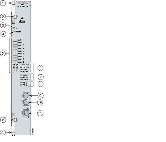
Figure 1-14 shows a close-up of the DS3+T1/E1 IMA NI-2 card faceplate.

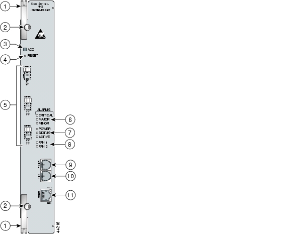
Figure 1-14 DS3+T1/E1 IMA NI-2 Card Faceplate

1

Ejector lever

7

Card status LED group

2

Locking tab

8

Fan alarm LED group

3

ACO button

9

CNSL—An RJ-45 receptacle that provides a serial connection to a system console.

4

Maintenance RESET port

10

AUX—An RJ-45 receptacle that provides connection to an auxiliary device (such as a modem) used to remotely configure the system.

5

Interface status LED groups: DS3 1, T1/E1 2, T1/E1 3, T1/E1 4, T1/E1 5, T1/E1 6, T1/E1 7, T1/E1 8, and T1/E1 9. These groups show the status of the trunk and subtend connections on the I/O module or I/O card

11

ENET—An RJ-45 10BaseT receptacle that complies with Ethernet standards and that provides connection to a system Ethernet.

6

System alarm LED group


Table 1-11 describes the LED group indicators and their functions.

Table 1-11 DS3+T1/E1 IMA NI-2 Card LED Group Indicators 

LED Group
LED
State
Function

Interface status LED (in Figure 1-14)

TEST

Amber solid

Cisco IOS detects that an obtrusive test (loopback) is active on this interface.

Off

Cisco IOS does not detect obtrusive test activity.

RX1 STAT

Amber solid

The receiver detects a physical layer problem.

Off

The receiver does not detect a physical layer problem.

TX2 STAT

Amber solid

The transmitter detects a physical layer problem.

Off

The transmitter does not detect a physical layer problem.

RCLK3

Green solid

Hardware detects an incoming clock signal.

Off

Hardware does not detect an incoming clock signal.

System alarm (in Figure 1-14)

CRITICAL

Red

A critical alarm is active.

MAJOR

Red

A major alarm is active.

MINOR

Amber

A minor alarm is active.

Card status (in Figure 1-14)

POWER

Green

The NI-2 card has power.

STATUS

Green

The operational status of the NI-2 card.

On—There are no internal faults or problems.

Off—The NI-2 card has not booted properly, or a problem is preventing normal operation.

ACTIVE

Green

The NI-2 card is operating as the active NI-2 card in the chassis.

Fan alarm (in Figure 1-14)

FAN 1

Red

The fan module or fan tray is not operational and is in alarm mode.

FAN 2

This LED on the NI-2 card is inactive and is always off.

ENET interface LED (11 in Figure 1-14)

ACT

Green solid or blinking

The Ethernet interface is active.

Off

The Ethernet interface is inactive.

LNK

Green solid

The Ethernet link is connected and enabled.

1 RX = receive

2 TX = transmit

3 RCLK = receive clock


1.2.4.2 DS3/2DS3 NI-2 Card Overview

This section provides the following information about DS3/2DS3 NI-2 cards:

Features

Faceplate Features

1.2.4.2.1 Features

In addition to the features described in the "NI-2 Cards" section, the DS3/2DS3 NI-2 card

Provides the network DS3 WAN trunk interface through Bayonet-Neill-Concelman (BNC) connectors located on the I/O card.

Provides two DS3 subtend interfaces through BNC connectors located on the I/O card.

Controls timing and redundancy.


Note The BITS interface is connected through the I/O card located on the back of the chassis.


Supports the aggregation of up to 12 subtended node chassis that are configured for DS3 operation in a tree topology.


Note For hardware specifications for the DS3/2DS3 NI-2 card, see the "DS3/2DS3 NI-2 Card Specifications" section on page A-9.


1.2.4.2.2 Faceplate Features

Figure 1-15 shows a close-up of the DS3/2DS3 NI-2 card faceplate.

Figure 1-15 DS3/2DS3 NI-2 Card Faceplate

1

Ejector lever

7

Card status LED group

2

Locking tab

8

Fan alarm LED group

3

ACO button

9

CNSL—An RJ-45 receptacle that provides a serial connection to a system console.

4

Maintenance RESET port

10

AUX—An RJ-45 receptacle that provides connection to an auxiliary device (such as a modem) used to remotely configure the system.

5

Interface status LED groups: Trunk 1 (TRNK 1), Subtend 2 (SBTD 2), and Subtend 3 (SBTD 3). These groups show the status of the trunk and subtend connections on the I/O card or I/O module.

11

ENET—An RJ-45 10BaseT receptacle that complies with Ethernet standards and that provides connection to a system Ethernet.

6

System alarm LED group


Table 1-12 describes the LED group indicators and their functions.

Table 1-12 DS3/2DS3 NI-2 Card LED Group Indicators 

LED Group
LED
State
Function

Interface status LED (in Figure 1-15)

TEST

Amber solid

Cisco IOS detects that an obtrusive test (loopback) is active on this interface.

Off

Cisco IOS does not detect obtrusive test activity.

RX STAT

Amber solid

The receiver detects a physical layer problem.

Off

The receiver does not detect a physical layer problem.

TX STAT

Amber solid

The transmitter detects a physical layer problem.

Off

The transmitter does not detect a physical layer problem.

RCLK

Green solid

Hardware detects an incoming clock signal.

Off

Hardware does not detect an incoming clock signal.

System alarm (in Figure 1-15)

CRITICAL

Red

A critical alarm is active.

MAJOR

Red

A major alarm is active.

MINOR

Amber

A minor alarm is active.

Card status (in Figure 1-15)

POWER

Green

The NI-2 card has power.

STATUS

Green

The operational status of the NI-2 card.

On—There are no internal faults or problems.

Off—The NI-2 card has not booted properly, or a problem is preventing normal operation.

ACTIVE

Green

The NI-2 card is operating as the active NI-2 card in the chassis.

Fan alarm (in Figure 1-15)

FAN 1

Red

The fan module or fan tray is not operational and is in alarm mode.

FAN 2

This LED on the NI-2 card is inactive and is always off.

ENET interface LED (11 in Figure 1-15)

ACT

Green solid or blinking

The Ethernet interface is active.

Off

The Ethernet interface is inactive.

LNK

Green solid

The Ethernet link is connected and enabled.


1.2.4.3 OC-3c/2DS3 NI-2 Card Overview

This section provides the following information about OC-3c/2DS3 NI-2 cards:

Features

Faceplate Features

1.2.4.3.1 Features

In addition to the features that are described in the "NI-2 Cards" section, the OC-3c/2DS3 NI-2 card

Provides the network OC-3c WAN trunk interface through connectors located on the NI-2 card faceplate. The following two versions of the OC-3c/2DS3 NI-2 card are available to support the WAN trunk interface:

Single-mode fiber (SMF) intermediate range.

Multimode fiber (MMF) short range.

Provides two DS3 subtend interfaces through BNC connectors located on the I/O card.

Controls timing and redundancy.


Note The BITS interface is connected through the I/O card located on the back of the chassis.


Supports the aggregation of up to 12 subtended node chassis configured for DS3 operation in a tree configuration.


Note For hardware specifications for the OC-3c/2DS3 NI-2 card, see the "OC-3c/2DS3 NI-2 Card Specifications" section on page A-10.


1.2.4.3.2 Faceplate Features

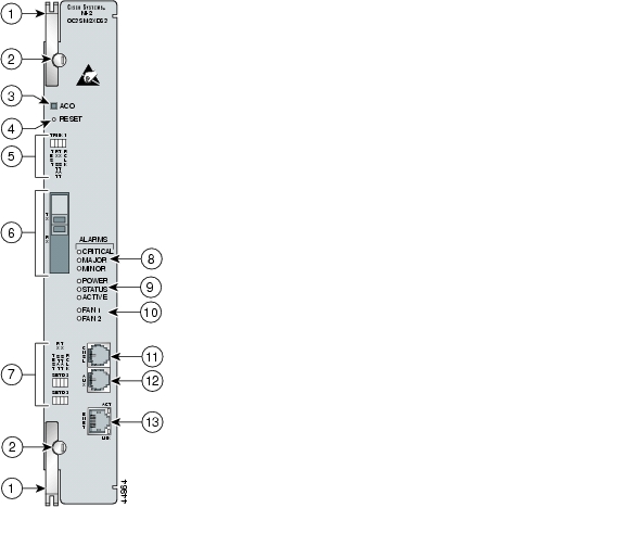
Figure 1-16 shows a close-up of the OC-3c/2DS3 NI-2 card faceplate.

Figure 1-16 OC-3c/2DS3 NI-2 Card Faceplate

1

Ejector lever

8

System alarm LED group

2

Locking tab

9

Card status LED group

3

ACO button

10

Fan alarm LED group

4

Maintenance RESET port

11

CNSL—An RJ-45 receptacle that provides a serial connection to a system console.

5

Interface status LED group: Trunk 1 (TRNK 1). This group shows the status of the OC-3c network trunk connection.

12

AUX—An RJ-45 receptacle that provides connection to an auxiliary device (such as a modem) used to remotely configure the system.

6

An optical interface connector pair. This connector pair is for network trunk interface TX and RX data optical cables.

13

ENET—An RJ-45 10BaseT receptacle that complies with Ethernet standards and that provides connection to a system Ethernet.

7

Two interface status LED groups: Subtend 2 (SBTD 2) and Subtend 3 (SBTD 3). These LED groups monitor the DS3 subtend connections on the I/O card.


Table 1-13 describes the LED group indicators and their functions.

Table 1-13 OC-3c/2DS3 NI-2 Card LED Group Indicators 

LED Group
LED
State
Function

Interface status LED (and 7 in Figure 1-16)

TEST

Amber solid

Cisco IOS detects that an obtrusive test (loopback) is active on this interface.

Off

Cisco IOS does not detect obtrusive test activity.

RX STAT

Amber solid

The receiver detects a physical layer problem.

Off

The receiver does not detect a physical layer problem.

TX STAT

Amber solid

The transmitter detects a physical layer problem.

Off

The transmitter does not detect a physical layer problem.

RCLK

Green solid

Hardware detects an incoming clock signal.

Off

Hardware does not detect an incoming clock signal.

System alarm (in Figure 1-16)

CRITICAL

Red

A critical alarm is active.

MAJOR

Red

A major alarm is active.

MINOR

Amber

A minor alarm is active.

Card status (in Figure 1-16)

POWER

Green

The NI-2 card has power.

STATUS

Green

The operational status of the NI-2 card.

On—There are no internal faults or problems.

Off—The NI-2 card has not booted properly, or a problem is preventing normal operation.

ACTIVE

Green

The NI-2 card is operating as the active NI-2 card in the chassis.

Fan alarm (10 in Figure 1-16)

FAN 1

Red

The fan module or fan tray is not operational and is in alarm mode.

FAN 2

This LED on the NI-2 card is inactive and is always off.

ENET interface LED (13 in Figure 1-16)

ACT

Green solid or blinking

The Ethernet interface is active.

Off

The Ethernet interface is inactive.

LNK

Green solid

The Ethernet link is connected and enabled.


1.2.4.4 OC-3c/OC-3c NI-2 Card Overview

This section provides the following information about OC-3c/OC-3c NI-2 cards:

Features

Faceplate Features

1.2.4.4.1 Features

In addition to the features described in the "NI-2 Cards" section, the OC-3c/OC-3c NI-2 card

Provides the network OC-3c WAN trunk interface through connectors located on the NI-2 card faceplate. The following two versions of the OC-3c/OC-3c NI-2 card are available to support the WAN trunk interface:

SMF intermediate range.

MMF short range.

Provides an OC-3c subtend interface through optical connectors located on the NI-2 card faceplate.

Controls timing and redundancy.


Note The BITS interface is connected through the I/O card located on the back of the chassis.


Supports the aggregation of up to 12 subtended node chassis configured for OC-3c operation in a daisy chain configuration.


Note For hardware specifications for the OC-3c/OC-3c NI-2 card, see the "OC-3c/OC-3c NI-2 Card Specifications" section on page A-11.


1.2.4.4.2 Faceplate Features

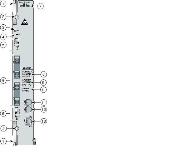
Figure 1-17 shows a close-up of the OC-3c/OC-3c NI-2 card faceplate.

Figure 1-17 OC-3c/OC-3c NI-2 Card Faceplate

1

Ejector lever.

7

Model number

2

Locking tab.

8

System alarm LED group.

3

ACO button.

9

Card status LED group.

4

Maintenance RESET port.

10

Fan alarm LED group.

5

Interface status LED groups: Trunk 1 (TRNK 1) and Subtend 2 (SBTD 2). These groups show the status of the trunk and subtend connections.

11

CNSL—An RJ-45 receptacle that provides a serial connection to a system console.

6

Two optical interface connector pairs: Trunk 1 (TRNK 1) and Subtend 2 (SBTD 2)

TRNK 1—This connector pair is for network trunk interface TX and RX data optical cables. On a subtended node chassis, these network trunk interface TX and RX cables connect to SBTD 2 on the subtending host chassis.

SBTD 2—This connector pair is for subtended node chassis TX and RX data optical cables.

12

AUX—An RJ-45 receptacle that provides connection to an auxiliary device (such as a modem) used to remotely configure the system.

   
13

ENET—An RJ-45 10BaseT receptacle that complies with Ethernet standards and that provides connection to a system Ethernet.


Table 1-14 describes the LED group indicators and their functions.

Table 1-14 OC-3c/OC-3c NI-2 Card LED Group Indicators 

LED Group
LED
State
Function

Interface status LED (in Figure 1-17)

TEST

Amber solid

Cisco IOS detects that an obtrusive test (loopback) is active on this interface.

Off

Cisco IOS does not detect obtrusive test activity.

RX STAT

Amber solid

The receiver detects a physical layer problem.

Off

The receiver does not detect a physical layer problem.

TX STAT

Amber solid

The transmitter detects a physical layer problem.

Off

The transmitter does not detect a physical layer problem.

RCLK

Green solid

Hardware detects an incoming clock signal.

Off

Hardware does not detect an incoming clock signal.

System alarm (in Figure 1-17)

CRITICAL

Red

A critical alarm is active.

MAJOR

Red

A major alarm is active.

MINOR

Amber

A minor alarm is active.

Card status (in Figure 1-17)

POWER

Green

The NI-2 card has power.

STATUS

Green

The operational status of the NI-2 card.

On—There are no internal faults or problems.

Off—The NI-2 card has not booted properly, or a problem is preventing normal operation.

ACTIVE

Green

The NI-2 card is operating as the active NI-2 card in the chassis.

Fan alarm (in Figure 1-17)

FAN 1

Red

The fan module or fan tray is not operational and is in alarm mode.

FAN 2

This LED on the NI-2 card is inactive and is always off.

ENET interface LED (12 in Figure 1-17)

ACT

Green solid or blinking

The Ethernet interface is active.

Off

The Ethernet interface is inactive.

LNK

Green solid

The Ethernet link is connected and enabled.


1.2.4.5 Network Clocking Overview

The NI-2 card receives its network timing signal from any one of the following sources:

BITS clock. When a BITS clock serves as the network timing signal source, the chassis receives a clock signal through designated pins on the I/O card and distributes the signal through the chassis backplane.

Internal clock.

DS3, OC-3c, or T1 network trunk interface. An NI-2 card synchronizes with the network timing source and provides a clock reference signal to line cards in the chassis and to subtended node chassis.

1.2.4.6 Redundancy Overview

The following forms of redundancy are available for the Cisco 6160 system:

NI-2 card cold redundancy, which allows a standby NI-2 card to take over system operations in the event of a complete failure of the active NI-2 card.

Automatic protection switching (APS) link redundancy, which provides recovery from a cut fiber or the failure of an OC-3c optical transmitter or optical receiver interface on an NI-2 card. APS redundancy is available on OC-3c/2DS3 NI-2 card trunk interfaces and OC-3c/OC-3c NI-2 card trunk and subtend interfaces.


Note Line card redundancy is not supported.


1.2.4.6.1 NI-2 Card Cold Redundancy

NI-2 card cold redundancy requires that two NI-2 cards be installed in the chassis. The primary card is installed in slot 10 of the chassis, and the secondary card is installed in slot 11. Either the primary or the secondary NI-2 card can serve as the active NI-2 card. The interface types must be the same for both the primary and secondary NI-2 cards.

During steady-state operations, one NI-2 card functions as the active unit, and the other functions as the standby unit. The active NI-2 card displays a green ACTIVE LED. In an active state, the NI-2 card

Has full Ethernet, auxiliary port, and console access

Communicates with line cards

Has full access to the environmental monitoring subsystem

Has access to the optical interfaces on the standby NI-2 card

Allows remote access to the file system of the standby NI-2 card

The standby NI-2 card plays a minimal role during steady-state operations. In a standby state, the NI-2 card

Receives configuration changes from the active NI-2 card (when the cards are configured for synchronization)

Has no Ethernet, auxiliary port, or console access

Does not communicate with line cards

Has no access to the environmental monitoring subsystem

Generates only APS alarms, which are reported via the active card

For management purposes, the primary and secondary NI-2 cards appear as one element. The cards share one IP address.


Note For information on NI-2 card cold redundancy switchover conditions, refer to the Upgrading DSLAMs for NI-2 Card and APS Link Redundancy document.


1.2.4.6.2 APS Link Redundancy

APS link redundancy provides recovery from a cut fiber or the failure of an OC-3c optical transmitter or receiver interface on an NI-2 card. APS link redundancy is available on OC-3c/2DS3 NI-2 card trunk interfaces and OC-3c/OC-3c NI-2 card trunk and subtend interfaces.

The working link is the fiber connection between the ATM switch and the primary NI-2 card installed in slot 10 of the chassis. The protection link is the fiber connection between the ATM switch and the secondary NI-2 card installed in slot 11 of the chassis. When the fiber or optical ports on the active NI-2 card fail, that card remains active but is able to use the fiber or optical ports on the standby NI-2 card.

APS protocol information is carried over the protection link connected to the secondary NI-2 card in slot 11. The standby NI-2 card continually reports Synchronous Optical Network (SONET) state information to the active NI-2 card.

APS link redundancy is nonrevertive. For example, after a switchover from the working to the protective link occurs, the active NI-2 card switches back to the working fiber only if manually forced through a CLI command or if a failure condition occurs on the protection link. However, if a failure condition occurs on the protection link while the working link is still in a failed state, a switch back to the working link does not occur.


Note For information on APS link redundancy switchover conditions, refer to the Upgrading DSLAMs for NI-2 Card and APS Link Redundancy document.


1.2.4.6.3 Redundancy in Subtended Configurations

NI-2 card redundancy is supported in a DS3 subtend tree or in an OC-3c subtend daisy-chain if both the subtending host chassis and the subtended node chassis have primary and secondary NI-2 cards installed. An NI-2 card failure on a node in a subtend tree or daisy-chain temporarily interrupts traffic to all subtended node chassis.

APS link redundancy is supported in subtending configurations only if the subtending host chassis has a secondary (redundant) OC-3c/OC-3c or OC-3c/2DS3 NI-2 card installed.


Note For more information about subtending and subtended network configurations, see the "Subtended Network Configuration" section.


1.2.5 I/O Cards

Table 1-15 lists the Cisco 6160 I/O cards and NI-2 card compatibility.

Table 1-15 I/O Card and NI-2 Card Compatibility 

I/O Card
NI-2 Card
DS3+T1/E1 IMA
DS3/2DS3
OC-3c/2DS3
OC-3c/OC-3c

DS3/2DS3+8xT1 IMA

Yes

Yes

Yes

Yes

DS3/2DS3

No

Yes

Yes

Yes


The following sections provide details about the Cisco 6160 I/O cards.

DS3/2DS3+8xT1 IMA I/O Card Overview

DS3/2DS3 I/O Card Overview

1.2.5.1 DS3/2DS3+8xT1 IMA I/O Card Overview

This section provides the following information about DS3/2DS3+8xT1 IMA I/O cards

Features

DS3/2DS3+8xT1 IMA I/O Card Wire-Wrap Pinss

1.2.5.1.1 Features

A DS3/2DS3+8xT1 IMA I/O card

Provides the following trunk and subtending interfaces:

Up to three DS3.

Up to eight T1.

Up to eight T1 IMA group.


Note For more information on IMA group interfaces, refer to the T1/E1 Inverse Multiplexing Over ATM feature module.


Provides, when used with the OC-3c/OC-3c NI-2 card, one network OC-3c WAN trunk interface and one OC-3c subtend interface through connectors located on the NI-2 card faceplate.

Provides five rows of six wire-wrap pins located on the right side of the DS3/2DS3+8xT1 IMA I/O card that support central office alarm relay interfaces (visual and audible) between the NI-2 card and the subscriber and BITS clock input circuits.

Supports up to 12 additional subtended node chassis, configured for DS3, T1, or T1 IMA operation.


Note For hardware specifications for the DS3/2DS3+8xT1 IMA I/O card, see the "DS3/2DS3+8xT1 IMA I/O Card Specifications" section on page A-12.


Figure 1-18 shows a close-up of the DS3/2DS3+8xT1 IMA I/O card with the EMI cover installed.

Figure 1-18 DS3/2DS3+8xT1 IMA I/O Card with the EMI Cover

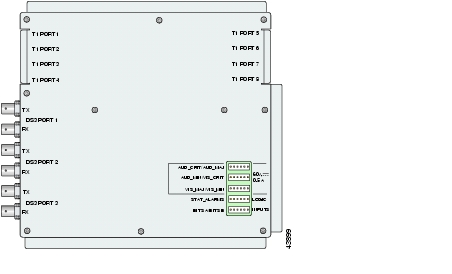
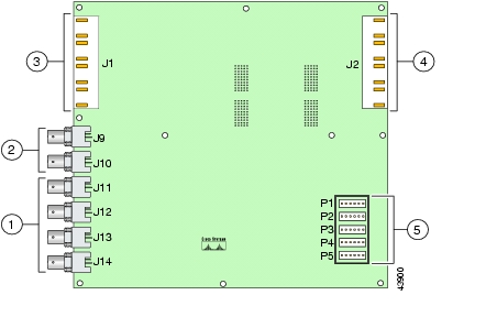
Figure 1-19 shows a close-up of the DS3/2DS3+8xT1 IMA I/O card without the EMI cover installed.

Figure 1-19 DS3/2DS3+8xT1 IMA I/O Card Without the EMI Cover

1

DS3 downstream subtend interface connectors (Port 2 and Port 3)

4

Four RJ-48c receptacles for T1 interfaces (T1 Port 5 through Port 8)

2

DS3 trunk interface or upstream subtend interface connectors (Port 1)

5

Wire wrap connectors that support central office alarm relay interfaces and BITS clock input circuits

3

Four RJ-48c receptacles for T1 interfaces (T1 Port 1 through Port 4)


Note For pinouts of the RJ-48c receptacles, see the Pin Assignments for the RJ-48c Receptacles, page 4.


The DS3/2DS3+8xT1 IMA I/O card provides three sets of two vertically paired DS3 75-ohm BNC coaxial cable connectors that are located on the left side of the DS3/2DS3+8xT1 IMA I/O card. Each set of port connectors has both a TX connector and a RX connector. Table 1-16 lists the DS3 BNC connector sets in relation to the NI-2 cards available for the Cisco 6160 chassis.

Table 1-16 DS3/2DS3+8xT1 IMA I/O Card BNC Connector Set Functions with the NI-2 Cards 

NI-2 Card
Chassis configuration
DS3 BNC Connector Sets
Port 1
Port 2
Port 3

DS3+T1/E1 IMA

Subtending host chassis

DS3 Trunk interface (optional). You can also use any T1 receptacle connector for the T1 or T1 IMA trunk interface.

Not in use. Use the T1 receptacle connectors for T1 or T1 IMA subtend interfaces.

Subtended node chassis

Not in use. Use the T1 receptacle connectors for T1 or T1 IMA subtend interfaces.

DS3/2DS3

Subtending host chassis

Trunk interface.

Downstream subtend interface.

Subtended node chassis

Upstream subtend interface.

Downstream subtend interface.

OC-3c/2DS3

Subtending host chassis

Not in use.

Downstream subtend interface.

Subtended node chassis

Upstream subtend interface.

Downstream subtend interface.

OC-3c/OC-3c

Subtending host chassis

Not in use. The trunk and subtend interfaces are located on the NI-2 card.

Subtended node chassis

Not in use. The trunk and subtend interfaces are located on the NI-2 card.


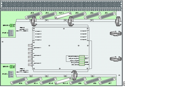
The DS3/2DS3+8xT1 IMA I/O card is delivered installed and attached to the two 2-mm HM card connectors, P3 and P9, on the chassis backplane (see Figure 1-20). The DS3/2DS3+8xT1 IMA I/O card is shown with the metal EMI cover installed.

Figure 1-20 DS3/2DS3+8xT1 IMA I/O Card Location on the Cisco 6160 Chassis Backplane

1.2.5.1.2 DS3/2DS3+8xT1 IMA I/O Card Wire-Wrap Pins

There are 30 wire-wrap pins located on the right side of each DS3/2DS3+8xT1 IMA I/O card that support

Central office alarm relay interfaces (visual and audible) between the NI-2 card and the subscriber.

BITS clock input circuits.

Wire wrap and socket type connections. A six-pin connector, Molex 26-03-3061, can be used to mate with each of the five headers.


Note The relay for the circuit-breaker trip alarm is wired through the small green terminal blocks on the rear of the chassis, not through the wire-wrap connector.


Both the alarm relays and the BITS clock connections are optional. If you connect the alarm relays, they transmit critical, major, and minor alarms to a separate, external alarm device. The alarm device uses a bell, light, or some other signal to alert service personnel to the change in system status. If you connect the BITS interface, the Cisco 6160 can receive a clock signal from a T1 line.

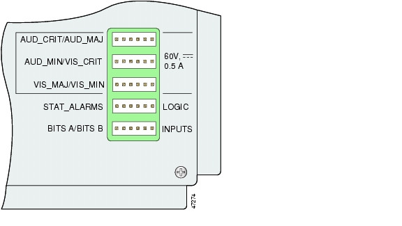
Figure 1-21 shows a close-up of the wire-wrap pins.

Figure 1-21 DS3/2DS3+8xT1 IMA I/O Card Wire-Wrap Pins Close-Up

These pins support the following alarm functions:

Visual critical

Visual major

Visual minor

Audible critical

Audible major

Audible minor

Remote alarm cut off

Reserved (several pins are reserved for future specification)

Alarm pins are wired to both NI-2 cards, however, only one NI-2 card manages the alarms. The ACO switch that is located on the NI-2 card faceplate shuts off the audible alarms generated by the Cisco 6160 system software.

One of the alarm relay functions provided by the wire-wrap connector is an ACO circuit that you can wire to your external alarm device. To use this feature, connect the alarm device so that it can close the contact between pin 5 and pin 6 in the STAT_ALARMS row.

The connector also provides contacts for the following features, all of which can be used (or not used) separately:

Audible alarms—Wire pins whose signals begin with AUD

Visible alarms—Wire pins whose signals begin with VIS

BITS clock—Wire pins whose signals begin with RX_BITS


Note There is one set of contacts for audible alarms and one set for visual alarms. You can use either or both sets of contacts.


You can wire the alarm relay contacts as normally open (NO) or normally closed (NC); however, the ACO circuit can be wired as NO only. Use common (CO) pins for both the NO and NC wiring methods.

Wiring Method
Pins to Use

Normally open

Pin 2 in rows P1, P2, P3 (NO)
Pin 5 in rows P1, P2, P3, P4 (NO)
Pin 1 in rows P1, P2, P3 (CO)
Pin 4 in rows P1, P2, P3 (CO)
Pin 6 in row P4 (GND1 )

Normally closed

Pin 3 in rows P1, P2, P3 (NC)
Pin 6 in rows P1, P2, P3 (NC)
Pin 1 in rows P1, P2, P3 (CO)
Pin 4 in rows P1, P2, P3 (CO)

1 GND = ground


Note For more information on how the wire-wrap pins map to the alarms, see the "DS3/2DS3+8xT1 IMA I/O Card Wire-Wrap Pin Mapping" section on page C-2.

The BITS pins on Cisco 6160 DS3/2DS3+8xT1 IMA I/O card are slot specific. BITS_A pins are assigned to slot 11 and BITS_B pins are assigned to slot 10. Each BITS clock input is independent and terminated at 100 ohms.


1.2.5.2 DS3/2DS3 I/O Card Overview

This section provides the following information about DS3/2DS3 I/O cards

Features

DS3/2DS3+8xT1 IMA I/O Card Wire-Wrap Pinss

1.2.5.2.1 Features

A DS3/2DS3 I/O card

Provides one DS3 trunk interface and two DS3 subtend interfaces.

Provides, when used with the OC-3c/OC-3c NI-2 card, one network OC-3c WAN trunk interface and one OC-3c subtend interface through connectors located on the NI-2 card faceplate.

Provides five rows of six wire-wrap pins located on the right side of the DS3/2DS3 I/O card that support central office alarm relay interfaces (visual and audible) between the NI-2 card and the subscriber and BITS clock input circuits.

Supports up to 12 additional subtended node chassis, configured for DS3 operation.


Note For hardware specifications for the DS3/2DS3 I/O card, see the "DS3/2DS3 I/O Card Specifications" section on page A-12.


Figure 1-22 shows a close-up of the DS3/2DS3 I/O card with the EMI cover installed.

Figure 1-22 DS3/2DS3 I/O Card with the EMI Cover

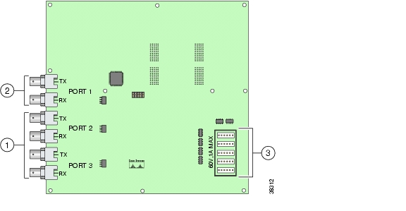
Figure 1-23 shows a close-up of the DS3/2DS3 I/O card without the EMI cover installed.

Figure 1-23 DS3/2DS3 I/O Card Without the EMI Cover

1

DS3 downstream subtend interface connectors (Port 2 and Port 3)

3

Wire wrap connectors that support central office alarm relay interfaces and BITS clock input circuits

2

DS3 trunk interface or upstream subtend interface connectors (Port 1)


The DS3/2DS3 I/O card provides three sets of two vertically paired DS3 75-ohm BNC coaxial cable connectors that are located on the left side of the DS3/2DS3 I/O card. Each set of port connectors has both a TX connector and a RX connector. Table 1-17 lists the DS3 BNC connector sets in relation to the NI-2 cards available for the Cisco 6160 chassis.

Table 1-17 DS3/2DS3 I/O Card BNC Connector Set Functions with the NI-2 Cards 

NI-2 Card
Chassis configuration
DS3 BNC Connector Sets
Port 1
Port 2
Port 3

DS3/2DS3

Subtending host chassis

Trunk interface.

Downstream subtend interface.

Subtended node chassis

Upstream subtend interface.

Downstream subtend interface.

OC-3c/2DS3

Subtending host chassis

Not in use.

Downstream subtend interface.

Subtended node chassis

Upstream subtend interface.

Downstream subtend interface.

OC-3c/OC-3c

Subtending host chassis

Not in use. The trunk and subtend interfaces are located on the NI-2 card.

Subtended node chassis

Not in use. The trunk and subtend interfaces are located on the NI-2 card.


The DS3/2DS3 I/O card is delivered installed and attached to the two 2-mm HM card connectors, P3 and P9, on the chassis backplane (see Figure 1-24). The DS3/2DS3 I/O card is shown with the metal EMI cover installed.

Figure 1-24 DS3/2DS3 I/O Card Location on the Cisco 6160 Chassis Backplane

1.2.5.2.2 DS3/2DS3 I/O Card Wire-Wrap Pins

There are 30 wire-wrap pins located on the right side of each DS3/2DS3 I/O card that support

Central office alarm relay interfaces (visual and audible) between the NI-2 card and the subscriber.

BITS clock input circuits.

Wire wrap and socket type connections. A six-pin connector, Molex 26-03-3061, can be used to mate with each of the five headers.


Note The relay for the circuit-breaker trip alarm is wired through the small green terminal blocks on the rear of the chassis, not through the wire-wrap connector.


Both the alarm relays and the BITS clock connections are optional. If you connect the alarm relays, they transmit critical, major, and minor alarms to a separate, external alarm device. The alarm device uses a bell, light, or some other signal to alert service personnel to the change in system status. If you connect the BITS interface, the Cisco 6160 can receive a clock signal from a T1 line.

One of the alarm relay functions provided by the wire-wrap connector is an ACO circuit that you can wire to your external alarm device. To use this feature, connect the alarm device so that it can close the contact between pin 5 and pin 6 in row P4.

The connector also provides contacts for the following features, all of which can be used (or not used) separately:

Audible alarms—Wire pins whose signals begin with AUD

Visible alarms—Wire pins whose signals begin with VIS

Power alarms—Wire pins whose signals begin with PEM

BITS clock—Wire pins whose signals begin with RX_BITS


Note There is one set of contacts for audible alarms and one set for visual alarms. You can use either or both sets of contacts.


You can wire the alarm relay contacts as NO or NC; however, the ACO circuit can be wired as NO only. Use CO pins for both the NO and NC wiring methods.

Wiring Method
Pins to Use

Normally open

Pin 2 in rows P1, P2, P3 (NO)
Pin 5 in rows P1, P2, P3, P4 (NO)
Pin 1 in rows P1, P2, P3 (CO)
Pin 4 in rows P1, P2, P3 (CO)
Pin 6 in row P4 (GND)

Normally closed

Pin 3 in rows P1, P2, P3 (NC)
Pin 6 in rows P1, P2, P3 (NC)
Pin 1 in rows P1, P2, P3 (CO)
Pin 4 in rows P1, P2, P3 (CO


Note For more information on how the wire-wrap pins map to the alarms, see the "DS3/2DS3 I/O Card Wire-Wrap Pin Mapping" section on page C-4.

The BITS pins on Cisco 6160 DS3/2DS3 I/O card are slot specific. BITS_A pins are assigned to slot 11 and BITS_B pins are assigned to slot 10. Each BITS clock input is independent and terminated at 100 ohms.


1.2.6 PEM

The Cisco 6160 chassis is equipped with one or two -48VDC PEMs, which distribute direct current (DC) power within the chassis. The Cisco 6160 needs only one active PEM to operate; if two PEMs are installed, a secondary PEM serves as a hot backup to the first PEM.

Each PEM should be connected to a single DC power source. For full power redundancy, two PEMs must be installed and connected to two separate DC power sources.

The primary Cisco 6160 PEM is located in the bottom right slot of the Cisco 6160 chassis. If you have a redundant system, a secondary PEM is located in the top right slot of the chassis. Figure 1-7 shows the location of the PEMs in the Cisco 6160 chassis.

The PEM provides the following features:

Redundancy, when a secondary PEM is installed. Either the primary or secondary PEM can serve as the active PEM. If the active PEM fails, the standby PEM powers up and becomes active.

A maximum of 1200 watts of -48VDC power to the Cisco 6160 backplane connector.

System earth ground bond integrity.

Circuit breaker control handles, which are accessible from the front panel.

Circuit breaker auxiliary alarm contacts, which remotely signal the status of the tripped breaker.

Reverse polarity protection.

Internal cooling fans.


Note For hardware specifications for the PEM, see the "PEM Specifications" section on page A-13.


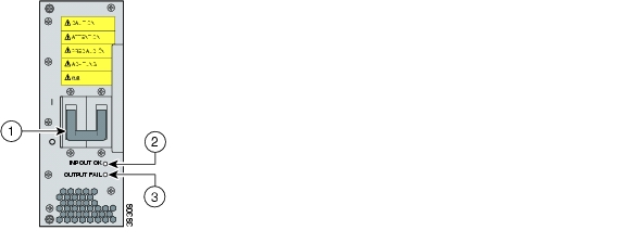
Figure 1-25 shows a close-up of the PEM faceplate.

Figure 1-25 PEM Faceplate

1

Two-position circuit breaker. The positions are Off (0) and On (1).

3

OUT FAIL LED.

2

INPUT OK LED.


Note To power down a Cisco 6160 that has two PEMs installed, you must flip the circuit breakers on both PEMs to the Off (0) position.


Table 1-18 describes the LEDs on the PEM.

Table 1-18 PEM LEDs 

LED
State
Function

INPUT OK

Green

-48VDC power is available to the chassis.

Off

The PEM has a power failure.

OUT FAIL

Red

One or both of the following conditions exists:

The PEM is not distributing power to the chassis.

The PEM is not distributing power to its cooling fans.


1.2.7 Blower Tray

The Cisco 6160 chassis is equipped with a blower tray, which provides forced air cooling required by all Cisco 6160 system circuit cards.

The Cisco 6160 blower tray is located in the top slot above the xTU-C line cards and NI-2 cards. Figure 1-7 shows the location of the blower tray in the Cisco 6160 chassis.

The blower tray

Is hot swappable.

Contains four blowers in each assembly unit.

Is accessible from the front of the Cisco 6160.

Has adequate system cooling with a single blower failure.

Has two speeds, which are controlled by the NI-2 card. By default, it runs run at the lower speed. The blower speed increases when

The system senses high temperatures within the chassis.

One or more blowers fail.

The blower speed returns to normal (low speed) when

Temperatures within the chassis fall to acceptable levels.

All four blowers are operating normally.

Contains a front panel LED to indicate status of operation.


Note For hardware specifications for the blower tray, see the "Blower Tray Specifications" section on page A-13.


Caution The blowers must run continuously. The system might suffer thermal damage if the blowers stop for more than five minutes.

Figure 1-26 shows a close-up of the blower tray faceplate.

Figure 1-26 Blower Tray Faceplate

Table 1-19 describes the LED on the blower tray.

Table 1-19 Blower Tray LED 

State
Function

Green

The blower tray is operating normally.

Red

One or more blowers have failed. Replace the blower tray.

Off

One of the following has occurred:

The blower tray is receiving no power.

The blower tray LED is broken.

The blower tray has failed.


1.2.8 Air Filter

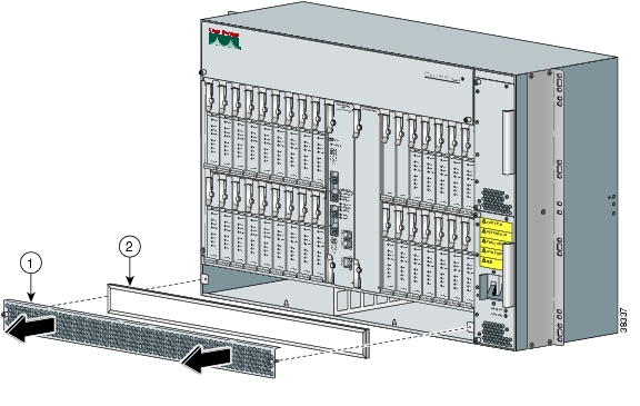
An air filter is located at the bottom of the chassis (see Figure 1-7 for location). The air filter must be removed and cleaned periodically. Once a month (or more often in dusty environments), examine the air filter and clean or replace it if it is dirty. Keep a log recording the date that the filter was cleaned or replaced.

See the "Air Filter Maintenance" section on page 6-36 for complete instructions on cleaning and replacing the air filter. Figure 1-27 shows the location of the air filter and the protective bezel that covers it.

Figure 1-27 Air Filter

1

Protective bezel

2

Air filter


1.3 Management Software

You can provision and manage the Cisco 6160 system through the following management software:

Cisco IOS—A CLI that is available for network element provisioning.

Cisco CDM—An element management system designed to configure and manage the 6xxx series of Cisco IOS software-based DSLAMs through a graphical-user interface (GUI). CDM provides the following areas of network management: fault, configuration, performance, and security. CDM runs within the Cisco Element Manager Framework (EMF); both are installed on Sun workstations.

Cisco EMF is based on an object model in which network elements or modules represent the managed entity. Each object is defined by a class and specific attributes. An object can represent a network element or a more abstract entity such as a link relationship, a network, or a container such as a site, shelf, or region.


Note If your network contains multiple Sun workstations, you must dedicate one workstation as the server and all additional workstations as clients. The server should be the repository and distributor of database information from which the clients request information. The client workstations allow multiple users to monitor the managed network.


Note See the Hardware Specifications, page A-1 for minimum software and network management release requirements per Cisco 6160 chassis component.


The Cisco 6160 includes CO alarm LED indicators and relays that indicate system status. You can wire CO facility alarm relay contacts for either normally open or normally closed operation. The supported alarms that are generated by the management software are:

CRITICAL—A critical alarm condition is indicated when the CRITICAL LED in the NI-2 card faceplate lights.

When a critical alarm occurs, the critical visual and audible alarm relays are activated.

A critical alarm affects many or all subscribers that are connected to the node. (For example, failure of the NI-2 card or the trunk can cause a critical alarm.)

Critical alarms clear after you fix the condition that triggered the alarm.

Audible alarms are turned off when you press the ACO button on the NI-2 card faceplate or clear the alarm in the Cisco IOS software.

MAJOR—A major alarm condition is indicated when the MAJOR LED in the NI-2 card faceplate lights.

When a major alarm occurs, the major visual and audible alarm relays are also activated.

Several subscribers that are connected to the node are affected.

Major alarms clear after you fix the condition that triggered the alarm.

Audible alarms are turned off when you press the ACO button on the NI-2 card faceplate or clear the alarm in the Cisco IOS software.

MINOR—A minor alarm condition is indicated when the MINOR LED in the NI-2 card faceplate lights.

When a minor alarm occurs, the minor visual and audible alarm relays are also activated.

A small number of subscribers that are connected to the node are affected.

Minor alarms clear after you fix the condition that triggered the alarm.

Audible alarms are turned off when you press the ACO button on the NI-2 card faceplate or clear the alarm in the Cisco IOS software.

Visual and audible alarm relay contacts can be wired from the Cisco 6160 to CO alarm devices (remote lights or bells) located anywhere within the facility.

The visual and audible alarm relays are located on the I/O card, but the NI-2 card hardware operates them.

For more information on alarms that are generated in the management software, see "Troubleshooting."


hometocprevnextglossaryfeedbacksearchhelp

Posted: Thu Feb 24 12:59:30 PST 2005
All contents are Copyright © 1992--2005 Cisco Systems, Inc. All rights reserved.
Important Notices and Privacy Statement.