cc/td/doc/product/dsl_prod/6160
hometocprevnextglossaryfeedbacksearchhelp
PDF

Table Of Contents

Installing a Cisco 6160 with a POTS Splitter Configuration

3.1 Installation Checklist

3.2 Installation Procedures

3.2.1 Stabilize and Measure the Rack Space

3.2.2 Install the Third-Party POTS Splitter

3.2.3 Install the Cisco 6160 Chassis

3.2.4 Install the Blank Faceplates

3.2.5 Ground the Cisco 6160

3.2.6 Ground the Third-Party POTS Splitter

3.2.7 Connect the Cisco 6160 to the Third-Party POTS Splitter

3.2.8 Attach the Cisco 6160 Power Connections

3.2.9 Connect the Alarm Contacts

3.2.10 Connect the BITS Clock Contacts

3.2.11 Connect the Third-Party POTS Splitter to the MDF or to the Cross Connect

3.2.12 Apply the Power

3.2.13 Connect the Subtending Host Chassis to the Subtended Node Chassis

3.2.14 Connect the NI-2 Card to the Network

3.2.15 Connect the Ethernet to the Management Network

3.2.16 Connect the Console Terminal

3.2.17 Connect the Auxiliary Port

3.2.18 Complete Initial Configuration


Installing a Cisco 6160 with a POTS Splitter Configuration


This chapter provides installation procedures for a Cisco 6160 with a POTS splitter configuration for xDSL data and voice traffic.


Note The installation procedures in this chapter apply to a Cisco 6160 system shipped with the individual hardware components preinstalled. For information about installing or replacing field-replaceable units (FRUs) in the Cisco 6160 chassis, see Chapter 6, "Upgrading and Maintaining the Cisco 6160 System."


Warning Only trained and qualified personnel should be allowed to install, replace, or service this equipment.


Caution Before you begin the installation procedures, read the entire chapter for important information and safety warnings.


Note Before installing and cabling the equipment, be aware of standard safety practices and the hazards involved in working with electrical circuitry to prevent accidents. See the "Safety Requirements" section for cautions and warnings that are necessary to ensure a safe and hazard-free installation.

To see translations of the warnings that appear in this publication, refer to the Regulatory Compliance and Safety Information for the Cisco 6160 System document that accompanied this product.


Note See the "Cisco 6160 with a POTS Splitter Configuration" section on page 1-4 for more information about configuration components.


3.1 Installation Checklist

When you install a Cisco 6160 with a POTS splitter configuration, be sure that you follow the installation procedures in the proper sequence. Table 3-1 is a checklist of the installation steps in the order in which they should occur. Detailed installation instructions are located in the sections following Table 3-1.


Caution Proper ESD protection is required whenever you handle Cisco equipment. Installation and maintenance personnel should be properly grounded by means of grounding straps to eliminate the risk of ESD damage to the equipment. Equipment is subject to ESD damage whenever it is removed from the chassis.

Table 3-1 Installation Checklist—Cisco 6160 with a POTS Splitter Configuration 

Check
Installation Procedure
 

1. Stabilize and measure the rack space.


2. Install the third-party POTS splitter(s) in the rack.


3. Install the Cisco 6160 chassis in the rack.


4. Install blank faceplates in the open line card slots.


5. Ground the Cisco 6160 chassis.


6. Ground the third-party POTS splitter.


7. Connect the Cisco 6160 chassis to the third-party POTS splitter.


8. Attach the Cisco 6160 power connections.


9. Connect the alarm contacts (optional).


10. Connect the BITS clock (optional).


11. Connect the third-party POTS splitter to the MDF1 or to the cross connect, as necessary.


12. Apply power to the system.


13. Connect the subtending host chassis to the subtended node chassis.


14. Connect the NI-2 card(s) to the network.


15. Connect the Ethernet to the management network.


16. Connect a console terminal.


17. Connect the auxiliary port (optional).


18. Complete the initial configuration.

1 MDF = main distribution frame


3.2 Installation Procedures

The following sections detail the installation procedures for a Cisco 6160 with a POTS splitter configuration.

3.2.1 Stabilize and Measure the Rack Space

For the rack to remain stable, you must install your Cisco 6160 system components from the bottom to the top of the rack. Before you install any of the components, calculate the total rack space required to install your system. The required rack space depends on the number of Cisco 6160 chassis and POTS splitters that you plan to use. The number of components increases if you plan to install a subtended network.


Note See Table 2-2 to determine the total rack necessary for your configuration.


Warning To prevent bodily injury when mounting or servicing this unit in a rack, you must take special precautions to ensure that the system remains stable. The following guidelines are provided to ensure your safety:

—This unit should be mounted at the bottom of the rack if it is the only unit in the rack.

—When mounting this unit in a partially filled rack, load the rack from the bottom to the top with the heaviest component at the bottom of the rack.

—If the rack is provided with stabilizing devices, install the stabilizers before mounting or servicing the unit in the rack.


Warning Two people are required to lift the chassis. Grasp the chassis underneath the lower edge and lift with both hands. To prevent injury, keep your back straight and lift with your legs, not your back.


If you plan to expand your system to include more chassis in the future, allow space in the rack for additions during the initial installation, keeping in mind the weight distribution and stability of the rack.

3.2.2 Install the Third-Party POTS Splitter

For installation procedures to install the third-party POTS splitter in the rack, refer to the appropriate vendor documentation.

3.2.3 Install the Cisco 6160 Chassis

Complete the following steps to install the Cisco 6160 chassis:


Warning Two people are required to lift the chassis. Grasp the chassis underneath the lower edge and lift with both hands. To prevent injury, keep your back straight and lift with your legs, not your back.


Step 1 Connect a grounding strap to the ESD grounding jack. See the "Preventing Electrostatic Discharge Damage" section for the ESD grounding jack location on the Cisco 6160 chassis.

Step 2 Check the ear brackets on the sides of the chassis and reinstall them, if necessary. Ear brackets can be installed in two ways:

Mid-mount, as shown in Figure 3-1—The ear brackets are installed in this position in the factory.

Front mount, as shown in Figure 3-2.

Figure 3-1 Mid-Mount Option for Ear Brackets

Figure 3-2 Front Mount Option for Ear Brackets

Step 3 Carefully lift the chassis from the bottom and place it above the POTS splitter in the rack.

Step 4 Use four mounting screws and a Phillips-head screwdriver to bolt the Cisco 6160 in the rack.

Step 5 Repeat Step 2 through Step 4 for each Cisco 6160 chassis as necessary.


3.2.4 Install the Blank Faceplates

Blank faceplates should occupy any empty line card slots in Cisco 6160 chassis. Blank faceplate installation is similar to line card installation.


Warning Blank faceplates and cover panels serve three important functions: they prevent exposure to hazardous voltages and currents inside the chassis; they contain electromagnetic interference (EMI) that might disrupt other equipment; and they direct the flow of cooling air through the chassis. Do not operate the system unless all cards, faceplates, and covers are in place.


Complete the following steps to install blank faceplates in the Cisco 6160:


Step 1 Vertically align the blank faceplate edges with the guides at the top and bottom of the slot.

Step 2 Lift up on the ejector lever and gently apply pressure to the bottom of the faceplate while pushing the blank faceplate into the slot.

Step 3 Push on the faceplate to fully seat the blank faceplate.

Step 4 Press down on the ejector lever to secure the faceplate.


3.2.5 Ground the Cisco 6160

This section describes two ways to ground the Cisco 6160 chassis.

Ground the Cisco 6160 Using a Grounding Lug

Ground the Cisco 6160 from the Power Terminal Block Connector

3.2.5.1 Ground the Cisco 6160 Using a Grounding Lug


Warning When you are installing or replacing the Cisco 6160 chassis, the ground connection must always be made first and disconnected last.


Note The grounding lug is not provided by Cisco. Use either a 5/8-inch or 3/4-inch lug to ground the Cisco 6160 chassis.


To ensure adequate earth ground for the system, complete the following steps to ground the Cisco 6160 chassis using a grounding lug:


Step 1 Verify that power in the direct current (DC) circuit is off.

Step 2 Measure enough wire to connect the Cisco 6160 to the grounding point at your site or to the rack.


Note See Table 2-4 for wire specifications.


Step 3 Use a wire stripper to remove the casing from both ends of the grounding wire. The manufacturer of the grounding lug might have a specific recommendation on the length of wire to be stripped.

Step 4 Insert the stripped end of the grounding wire into the open end of the grounding lug. Be careful not to leave any wire strands outside the lug.

Step 5 Use the crimping tool to compress the lug onto the wire.

Step 6 Verify the quality of the crimp by inspecting it and tugging gently on the wire.

Step 7 Locate the three grounding holes on the Cisco 6160 side panel. Figure 3-3 shows how to ground the Cisco 6160 chassis using a grounding lug.

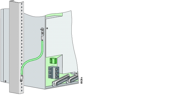
Figure 3-3 Grounding the Cisco 6160 Chassis Using the Grounding Lug—Backplane View

Step 8 Match the holes in the grounding lug to the appropriately spaced pair of grounding holes on the side of the chassis. Use the top two holes for a 5/8-inch lug. Use the bottom two holes for a 3/4-inch lug.

Step 9 Insert the screws through the holes in the lug and the chassis.

Step 10 Use a Phillips-head screwdriver to tighten the screws and secure the grounding lug firmly to the chassis.

Step 11 Connect the other end of the grounding wire to an appropriate grounding point at your site or to the rack (see Figure 3-3). To connect the grounding wire to the rack, complete the following steps:

a. Remove all paint or oxidation from the rack at the point of the grounding connection.

b. Use a 3/16-inch flat-head screwdriver to loosen the grounding screw on the rack.

c. Connect the wire to a ring lug (large enough for the rack screw to fit through).

d. Use a 3/16-inch flat-head screwdriver and the screw to attach the ring lug to the rack.

e. Tighten the grounding screw on the rack over the ring lug.

Step 12 Repeat Step 1 through Step 11 for each Cisco 6160 chassis being installed.


3.2.5.2 Ground the Cisco 6160 from the Power Terminal Block Connector


Warning When you are installing or replacing the Cisco 6160 chassis, the ground connection must always be made first and disconnected last.


To ensure adequate earth ground for the system, complete the following steps to attach the grounding wire to the power terminal block connector on the Cisco 6160 backplane:


Step 1 Verify that power in the DC circuit is off.

Step 2 Measure enough wire to connect the Cisco 6160 to the grounding point at your site or to the rack.


Note See Table 2-4 for wire specifications.


Step 3 Use a wire stripper to remove the casing from both ends of the grounding wire.

Step 4 Identify the correct power terminal block on the backplane of the Cisco 6160. The PWR 1 connector is used if you have a primary power entry module (PEM) installed in the chassis. The PWR 2 connector is used if you have a secondary (redundant) PEM installed in the chassis. Figure 3-4 shows the location of the PWR 1 and PWR 2 power terminal block connectors.

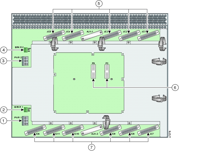
Figure 3-4 Cisco 6160 Backplane

1

PWR 1—Power terminal block connector.

5

Connectors JC1 through JC5.

2

BRKR 1—A terminal block connector used to wire alarm relays to external alarms.

6

I/O card connectors (P3 and P9).

3

PWR 2—Power terminal block connector. Use if a secondary (redundant) PEM is installed.

7

Connectors JC6 through JC11.

4

BRKR 2—A terminal block connector used to wire alarm relays to external alarms. Use if a secondary (redundant) PEM is installed.


Step 5 Use a flat-head screwdriver and a counterclockwise motion to open the grounding terminal connector on the power terminal block. This step ensures that the correct opening is presented for the wires. (See Figure 3-5.)

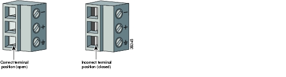
Figure 3-5 Positioning the Power and Ground Terminals to Accept Wires

Step 6 Insert one end of the grounding wire into the grounding receptacle, which is the bottom receptacle in the power terminal block connector (Callout 3 in Figure 3-6). The stripped part of the wire must be fully inserted into the terminal block so that no bare wire is exposed.

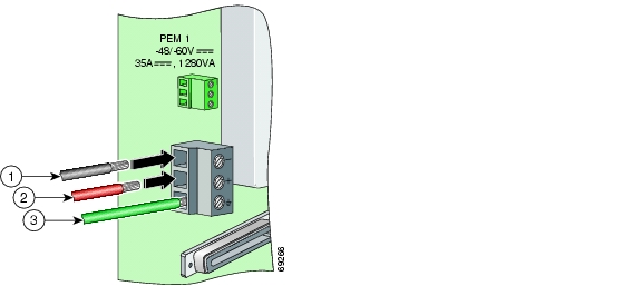
Figure 3-6 Inserting the Grounding and Power Wires into the Power Terminal Block Connector

1

Power lead wire connection

3

Grounding wire connection

2

Battery return wire connection


Step 7 Verify that no wire strands are left outside the connector.

Step 8 Use the flat-head screwdriver and a clockwise motion to tighten the ground screw in the power terminal block connector. Pull gently on the wire to ensure that it is held firmly in place. Figure 3-7 shows how to ground the Cisco 6160 chassis from the power terminal block connector.

Figure 3-7 Grounding the Cisco 6160 Chassis from the Power Terminal Block Connector—Backplane View

Step 9 Connect the other end of the grounding wire to an appropriate grounding point at your site or to the rack. (see Figure 3-7). To connect the grounding wire to the rack, complete the following steps:

a. Remove all paint or oxidation from the rack at the point of the grounding connection.

b. Use a 3/16-inch flat-head screwdriver to loosen the grounding screw on the rack.

c. Connect the wire to a ring lug (large enough for the rack screw to fit through).

d. Use a 3/16-inch flat-head screwdriver and the screw to attach the ring lug to the rack.

e. Tighten the grounding screw on the rack over the ring lug (see Figure 3-7).

Step 10 If you are connecting two power sources to the Cisco 6160 system, repeat Step 1 through Step 9 for the second power terminal block.

Step 11 Repeat Step 1 through Step 10 for each Cisco 6160 chassis being installed.


3.2.6 Ground the Third-Party POTS Splitter

For wire specifications and grounding procedures for each third-party POTS splitter, refer to the appropriate vendor documentation.


Note Do not ground the components in a rack by chaining them together.


3.2.7 Connect the Cisco 6160 to the Third-Party POTS Splitter

For cabling procedures for each third-party POTS splitter, refer to the appropriate vendor documentation.

3.2.8 Attach the Cisco 6160 Power Connections


Caution To prevent the system from powering up, do not install the fuses at this time. If the fuses are already installed in the fuse and alarm panel, remove them. You can replace the fuses after the system is installed and connected.


Note For full power redundancy, each terminal block must be connected to a separate power source. If you do not require power redundancy, you can wire a single terminal block, or connect both terminal blocks to a single power source.

Do not power the components in the rack by chaining them together.


Warning The illustration shows the DC power supply terminal block. Wire the DC power supply as illustrated. The proper wiring sequence is ground to ground, positive to positive, and negative to negative. The ground wire must always be connected first and disconnected last. The fuse and alarm panel and wires are not provided by Cisco.


Complete the following steps to connect power to the system:


Step 1 Verify that power in the DC circuit is off.

Step 2 Identify the correct power terminal block on the backplane of the Cisco 6160. The PWR 1 connector is used if you have a primary PEM installed in the chassis. The PWR 2 connector is used if you have a secondary (redundant) PEM installed in the chassis. Figure 3-4 shows the location of the PWR 1 and PWR 2 power terminal block connectors.

Step 3 Use a flat-head screwdriver and a counterclockwise motion to open the positive and negative terminal connectors on the power terminal block.This step ensures that the correct opening is presented for the wires. (See Figure 3-8.)

Figure 3-8 Positioning the Power and Ground Terminals to Accept Wires

Step 4 Insert the battery return wire from the first external power source into the receptacle labeled + (positive) on the appropriate power terminal block (Callout 2 in Figure 3-9). The stripped part of the wire must be fully inserted so that no bare wire is exposed.

Figure 3-9 Inserting the Grounding and Power Wires into the Power Terminal Block Connector

1

Power lead wire connection

3

Grounding wire connection

2

Battery return wire connection


Step 5 Verify that no wire strands are left outside the connector.

Step 6 Use a flat-head screwdriver and a clockwise motion to tighten the terminal screw over the wire.

Step 7 Insert the power lead from the first battery -48VDC power source into the receptacle labeled - (negative) on the appropriate power terminal block (Callout 1 in Figure 3-9). The stripped part of the wire must be fully inserted so that no bare wire is exposed.

Step 8 Verify that no wire strands are left outside the connector.

Step 9 Use a flat-head screwdriver and a clockwise motion to tighten the terminal screw over the wire.

Step 10 If you are connecting a second power source, repeat Step 2 through Step 9 to wire the second power terminal block.

Step 11 Thread tie wraps through the small cutouts in the side of the chassis next to each terminal block and tie down the wires using the tie wraps.

Step 12 Repeat Step 1 through Step 11 for each Cisco 6160 chassis being installed.


3.2.9 Connect the Alarm Contacts


Note This step is optional.


Complete the following steps to connect an external alarm device to the wire-wrap pins on the I/O card:


Note The relay for the circuit-breaker trip alarm is wired through the small green terminal blocks (BRKR 1 and BRKR 2) on the chassis backplane and not through the wire-wrap connector.


Caution Use extreme caution when wire-wrapping the pin connections for the STAT_ALARMS and BITS_A/BITS_B pins. Incorrect wire connections will cause damage to the equipment.


Step 1 Measure wire long enough to connect the appropriate pin to the external alarm device. See Table 2-4 for wire specifications.


Note See the "I/O Cards" section on page 1-43 for an illustration of the pinouts that are located on the I/O card. See Appendix C, "Connector and Pinout Specifications," for pinout descriptions.


Step 2 Use a wire stripper to remove the casing from both ends of the wire.

Step 3 Use a wire-wrapping tool to attach the wire to the appropriate pin.

Step 4 Use a wire-wrapping tool to attach the other end of the wire used in Step 3 to the external alarm device.

Step 5 Repeat Step 1 through Step 4 to wire wrap all necessary pins.

Step 6 Repeat Step 1 through Step 5 for each Cisco 6160 chassis being installed.


3.2.10 Connect the BITS Clock Contacts


Note This step is optional.


Complete the following steps to connect the BITS clock to the wire-wrap pins on the I/O card:


Caution Use extreme caution when wire-wrapping the pin connections for the STAT_ALARMS and BITS_A/BITS_B pins. Incorrect wire connections will cause damage to the equipment.


Step 1 Measure wire long enough to connect the appropriate pin on the I/O card to the BITS clock. See Table 2-4 for wire specifications.


Note See the "I/O Cards" section on page 1-43 for an illustration of the pinouts that are located on the I/O card. See Appendix C, "Connector and Pinout Specifications," for pinout descriptions.


Step 2 Use a wire stripper to remove the casing from both ends of the wire.

Step 3 Use a wire-wrapping tool to attach the wire to the appropriate pins for the slot in which the primary NI-2 card is installed.


Note The BITS pins on I/O cards are slot specific. BITS_A pins are assigned to slot 11 and BITS_B pins are assigned to slot 10. Each BITS clock input is independent and terminated at 100 ohms.


Step 4 Use a wire-wrapping tool to attach the other end of the wire used in Step 3 to the BITS clock.

Step 5 Repeat Step 1 through Step 4 to wire wrap the appropriate pins for a secondary (redundant) NI-2 card.

Step 6 Repeat Step 1 through Step 5 for each Cisco 6160 chassis being installed.


3.2.11 Connect the Third-Party POTS Splitter to the MDF or to the Cross Connect

For procedures about connecting the third-party POTS splitter to the MDF or to the cross connect, refer to the appropriate vendor documentation.

3.2.12 Apply the Power

Complete the following steps to apply power to the Cisco 6160 system:


Caution If the power connections are improperly made and power is applied while the cards are installed, the cards and chassis could be damaged.


Step 1 Verify that the power connections from the Cisco 6160 terminal block(s) to the power source are wired as shown in Figure 3-9.

Step 2 Apply power to the system using one of the following methods:

Install the fuses in the fuse and alarm panel.

Reinsert the fuses in the fuse and alarm panel, if you removed them in the "Attach the Cisco 6160 Power Connections" section.

Turn on the breakers in the fuse and alarm panel.

Step 3 Check the polarity of the -48VDC connections to each chassis by attaching a voltmeter with the minus lead on -48RTN and the plus lead on -48V_A or -48V_B. Ensure that the meter reads between -40VDC and -60VDC. If your voltmeter shows a positive voltage, the power inputs might be reversed. If the voltmeter shows a negative voltage that is out of the -40VDC to -60VDC range, check the power supply for failure or check for a blown fuse in the fuse and alarm panel.

Step 4 Set the circuit breaker on the PEM to the ON (1) position.

If the power is properly connected, the INPUT OK LED on the front of the PEM(s) will be green. You will also hear the blowers start to turn. A slight delay in blower startup is normal. If these events do not occur, repeat Step 1 through Step 4.

Step 5 Repeat Step 1 through Step 4 for each Cisco 6160 chassis being installed.


3.2.13 Connect the Subtending Host Chassis to the Subtended Node Chassis

If you are installing a subtended network, this section provides installation procedures for the following subtending connections:

DS3 Subtending Connections

OC-3c Subtending Connections

T1 or T1 IMA Subtending Connections

If you are not installing a subtended network, proceed to the "Connect the NI-2 Card to the Network" section.


Tip Cisco recommends that you label each data cable at both ends to identify its destination.


Note For more information on a subtended network configuration, see the "Subtended Network Configuration" section on page 1-6.

The term subtending refers to the host chassis, and subtended refers to the downstream chassis in a subtended network.

Cisco does not provide the cables for the subtending connections. See Table 2-4 for cable specifications.


3.2.13.1 DS3 Subtending Connections

Complete the following steps to connect the DS3 subtending connections:


Note For more information about DS3 subtending connections, see the "Subtended Network Configuration with DS3/2DS3 or OC-3c/2DS3 NI-2 Cards" section on page 1-9.


Step 1 Verify that the DS3/2DS3 or OC-3c/2DS3 NI-2 card is installed in slot 10 (or slot 11, if a secondary NI-2 card is installed for redundancy) of the Cisco 6160 chassis to ensure that the DS3 NI-2 card connections are active.


Note See the "Redundancy in Subtended Configurations" section on page 1-42 for more information about redundant configurations.


Step 2 On the subtending host chassis backplane, attach one end of a coaxial cable to the TX BNC connector for DS3 Port 2 on the I/O card.


Note See Table 2-4 for cable specifications. See Figure 1-19 or Figure 1-23 for DS3 port connector locations.


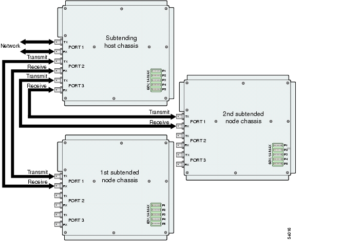
Figure 3-10 shows the cabling for a DS3 subtended network configuration.

Figure 3-10 Cabling for DS3 Subtended Network Configuration

Step 3 On the first subtended node chassis backplane, attach the end of the coaxial cable used in Step 2 to the RX BNC for DS3 Port 1 on the I/O card.

Step 4 On the subtending host chassis backplane, attach one end of a coaxial cable to the RX BNC connector for DS3 Port 2 on the I/O card.

Step 5 On the first subtended node chassis backplane, attach the end of the coaxial cable used in Step 4 to the TX BNC connector for DS3 Port 1 on the I/O card.

Step 6 On the subtending host chassis backplane, attach one end of a coaxial cable to the TX BNC connector for DS3 Port 3 on the I/O card.

Step 7 On the first subtended node chassis backplane, attach the end of the coaxial cable used in Step 6 to the RX BNC for DS3 Port 1 on the I/O card.

Step 8 On the subtending host chassis backplane, attach one end of a coaxial cable to the RX BNC connector for DS3 Port 3 on the I/O card.

Step 9 On the first subtended node chassis backplane, attach the end of the coaxial cable used in Step 8 to the TX BNC connector for DS3 Port 1 on the I/O card.

Step 10 Repeat Step 2 through Step 9 for each subtending host chassis.


3.2.13.2 OC-3c Subtending Connections

Complete the following steps to connect the OC-3c subtending connections:


Warning Do not stare into the beam or view it directly with optical instruments.


Note For more information about OC-3c subtending connections, see the "Subtended Network Configuration with OC-3c/OC-3c NI-2 Cards" section on page 1-10.


Step 1 Verify that the OC-3c/OC-3c NI-2 card is installed in slot 10 (or slot 11, if a secondary NI-2 card is installed for redundancy) of the Cisco 6160 chassis to ensure that the OC-3c NI-2 card connections are active.


Note See the "Redundancy in Subtended Configurations" section on page 1-42 for more information about redundant configurations.


Step 2 Attach a cable to the SBTD 2 RX optical interface connector on the subtending host chassis OC-3c/OC-3c NI-2 card to the TRNK 1 TX optical interface connector on the subtended node chassis OC-3c/OC-3c NI-2 card.

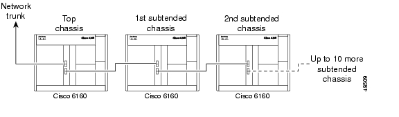
Figure 3-11 shows the cabling for an OC-3c subtended network configuration.


Note See Table 2-4 for cable specifications. See Figure 1-17 for OC-3c connector locations.


Figure 3-11 Cabling for OC-3c Subtended Network Configuration

Step 3 Attach a cable to the SBTD 2 TX optical interface connector on the subtending host chassis OC-3c/OC-3c NI-2 card to the TRNK 1 RX optical interface connector on the subtended node chassis OC-3c/OC-3c NI-2 card. (See Figure 3-11.)

Step 4 To establish APS link redundancy repeat Step 2 and Step 3 for a secondary OC-3c/OC-3c NI-2 card.

Step 5 Repeat Step 1 through Step 4 for each subtending host chassis.


3.2.13.3 T1 or T1 IMA Subtending Connections

Complete the following steps to connect the TI or TI IMA subtending connections:


Note For more information about T1 or T1 IMA subtending connections, see the "Subtended Network Configuration with DS3+T1/E1 IMA NI-2 Cards" section on page 1-7.


Step 1 Verify that the DS3+T1/E1 IMA NI-2 card is installed in slot 10 (or slot 11, if a secondary NI-2 card is installed for redundancy) and the DS3/2DS3+8xT1 IMA I/O card is installed on the chassis backplane.


Note See the "Redundancy in Subtended Configurations" section on page 1-42 for more information about redundant configurations.


Step 2 Connect one end of an RJ-48 cable to one of the RJ-48c receptacles on the DS3/2DS3+8xT1 IMA I/O card located on the subtending host chassis backplane.

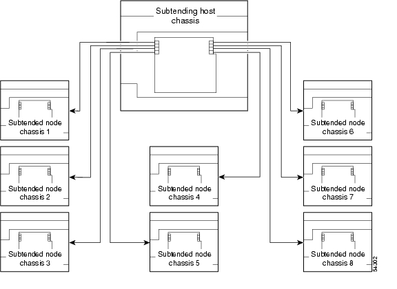
Figure 3-12 shows the cabling for a T1 or T1 IMA subtended network configuration.


Note See Table 2-4 for cable specifications. See Figure 1-19 for T1 interface locations.


Figure 3-12 Cabling for T1 or T1 IMA Subtended Network Configuration

Step 3 Connect the other end of the cable used in Step 2 to one of the RJ-48c receptacles on the DS3/2DS3+8xT1 IMA I/O card located on the subtended node chassis backplane.

Step 4 Repeat Step 1 through Step 3 for each subtending host chassis.


Note Verify that the RJ-48 cable pinouts connect transmit to receive and receive to transmit. For more information on the RJ-48c receptacle pinouts, see the "Pinouts for the DS3/2DS3+8xT1 IMA I/O Card RJ-48c Receptacles" section on page C-4.


3.2.14 Connect the NI-2 Card to the Network

This section provides installation procedures for the following network connections:

DS3 Network Connections

OC-3c Network Connections

T1 or T1 IMA Network Connections


Tip Cisco recommends that you label each data cable at both ends to identify its destination.


Note Cisco does not provide the cables for the network connections. See Table 2-4 for cable specifications.


3.2.14.1 DS3 Network Connections

Complete the following steps to connect the DS3 network connections:


Step 1 Verify that the DS3/2DS3 or DS3+T1/E1 IMA NI-2 card is installed in slot 10 (or slot 11, if a secondary NI-2 card is being installed for redundancy) of the Cisco 6160 chassis to ensure that the DS3 NI-2 card connections are active.


Note See the "Redundancy in Subtended Configurations" section on page 1-42 for more information about redundancy configurations.


Step 2 Attach one end of a coaxial cable to the TX BNC connector for DS3 Port 1 on the I/O card.


Note See Table 2-4 for cable specifications. See Figure 1-19 or Figure 1-23 for DS3 port connector locations.


Step 3 Attach the end of the cable that you used in Step 2 to the ATM switch.

Step 4 Attach one end of a coaxial cable to the RX BNC connector for DS3 Port 1 on the I/O card.

Step 5 Attach the end of the cable that you used in Step 4 to the ATM switch.

Step 6 Reboot the system to reassociate the system MAC address.

Step 7 Repeat Step 1 through Step 6 for each Cisco 6160 chassis being installed.


3.2.14.2 OC-3c Network Connections

Complete the following steps to connect the OC-3c network connections:


Warning Do not stare into the beam or view it directly with optical instruments.


Step 1 Verify that the OC-3c/OC-3c or OC-3c/2DS3 NI-2 card is installed in slot 10 (or slot 11, if a secondary NI-2 card is being installed for redundancy) of the Cisco 6160 chassis to ensure that the OC-3c NI-2 connections are active.


Note See the "Redundancy in Subtended Configurations" section on page 1-42 for more information about redundancy configurations.


Step 2 Attach the receive cable from the ATM switch to the TRNK 1 TX optical interface connector on the OC-3c/OC-3c or OC-3c/2DS3 NI-2 card.


Note See Figure 1-16 or Figure 1-17 or OC-3c connector locations.


Step 3 Attach the transmit cable from the ATM switch to the TRNK 1 RX optical interface connector on the OC-3c/OC-3c or OC-3c/2DS3 NI-2 card.

Step 4 To establish APS link redundancy repeat Step 2 and Step 3 for a secondary OC-3c/OC-3c or OC-3c/2DS3 NI-2 card.

Step 5 Reboot the system to reassociate the system MAC address.

Step 6 Repeat Step 1 through Step 5 for each Cisco 6160 chassis being installed.


3.2.14.3 T1 or T1 IMA Network Connections

Complete the following steps to connect the T1 or T1 IMA network connections:


Note See the "IMA Configuration" section on page 1-5 for more information on how to configure an IMA network connection.


Step 1 Verify that you have a DS3+T1/E1 IMA NI-2 card is installed in slot 10 (or slot 11, if a secondary NI-2 card is installed for redundancy) and the DS3/2DS3+8xT1 IMA I/O card is installed on the chassis backplane.


Note See the "Redundancy in Subtended Configurations" section on page 1-42 for more information about redundant configurations.


Step 2 Connect one end of an RJ-48 cable to one of the RJ-48c receptacles on the DS3/2DS3+8xT1 IMA I/O card. If you have a subtended network configuration installed, this connection must be made from the DS3/2DS3+8xT1 IMA I/O card in the subtending host chassis.


Note See Table 2-4 for cable specifications. See Figure 1-19 for T1 interface locations.


Step 3 Connect the other end of the cable used in Step 2 to the ATM switch.

Step 4 Repeat Step 1 through Step 3 for each Cisco 6160, as necessary.


Note Verify that the RJ-48 cable pinouts connect transmit to receive and receive to transmit. For more information on the RJ-48c receptacle pinouts, see the "Pinouts for the DS3/2DS3+8xT1 IMA I/O Card RJ-48c Receptacles" section on page C-4.


3.2.15 Connect the Ethernet to the Management Network

Complete the following steps to connect the Ethernet to the management network:


Warning The ports labeled "ENET," "CNSL," and "AUX" are safety extra-low voltage (SELV) circuits. SELV circuits should be connected only to other SELV circuits. Because the DSL circuits are treated like telephone-network voltage, avoid connecting the SELV circuit to the telephone network voltage (TNV) circuits.


Tip Cisco recommends that you label each data cable at both ends to identify its destination.


Step 1 Connect an Ethernet cable to the RJ-45 10BaseT receptacle (ENET) on the NI-2 card faceplate.


Note See Table 2-4 for cable specifications.


Step 2 Connect the other end of the Ethernet cable to the management network (for example, a LAN).


3.2.16 Connect the Console Terminal

Connect a VT100-compatible terminal to the system console port (CNSL) on the NI-2 card faceplate. Connect the terminal to a power source and set it up using the values that are shown in Table 3-2.

Table 3-2 Terminal Settings 

Baud rate

9600 (transmit and receive)

Character size

8 bits

Parity

None

Stop bits

1

Flow control

None


Warning The ports labeled "ENET," "CNSL," and "AUX" are safety extra-low voltage (SELV) circuits. SELV circuits should be connected only to other SELV circuits. Because the DSL circuits are treated like telephone-network voltage, avoid connecting the SELV circuit to the telephone network voltage (TNV) circuits.


3.2.17 Connect the Auxiliary Port


Note This step is optional.


Connect a terminal, a modem, or another serial device to the RJ-45 auxiliary port (AUX) on the NI-2 card faceplate.


Warning The ports labeled "ENET," "CNSL," and "AUX" are safety extra-low voltage (SELV) circuits. SELV circuits should be connected only to other SELV circuits. Because the DSL circuits are treated like telephone-network voltage, avoid connecting the SELV circuit to the TNV circuits.


Tip Cisco recommends that you label each data cable at both ends to identify its destination.


3.2.18 Complete Initial Configuration

When you turn on the Cisco 6160 for the first time, the System Configuration Dialog appears on the console screen. The System Configuration Dialog guides you through the initial configuration process. (You can run the dialog at any time by entering the setup command in privileged EXEC mode.)

When you complete the dialog, the system displays the configuration command script that you have created. It then offers you three options:

[0] Go to the IOS command prompt without saving this config.
[1] Return back to the setup without saving this config.
[2] Save this configuration to nvram and exit.

If you enter 2, the configuration is saved and used. If you answer 0 or 1, the configuration you created is not saved. Enter 1 if you wish to discard the configuration and restart the System Configuration Dialog.

3.2.18.1 Before You Begin

Complete the following steps before you run the System Configuration Dialog.


Step 1 Determine the IP address for the Ethernet interface.

Step 2 If you plan to configure in-band management, also determine the IP address for the ATM interface that will be used for in-band management (ATM0/0).

Step 3 Find out what the password strategy is for your environment. The System Configuration Dialog prompts you for three passwords, plus an SNMP community string. The three types of password required are enable secret, enable, and virtual terminal.

Step 4 Choose a name for the Cisco 6160. (This step is optional.)


3.2.18.2 Using the System Configuration Dialog

When you power up a Cisco 6160 for the first time, you are offered the option of running the System Configuration Dialog. The System Configuration Dialog offers two configuration options: basic management setup and extended setup.

Choose basic management setup if you want to use the System Configuration Dialog to configure the passwords and the Ethernet interface only, and then use the management station or the command line interface to configure the remaining Cisco 6160 interfaces.

Choose extended setup if you want to use the System Configuration Dialog to configure all of the Cisco 6160 interfaces.

An example of the use of each option follows the "Interface Numbering" section.

3.2.18.2.1 Interface Numbering

The System Configuration Dialog and the command line interface use the following interface numbering scheme:

Interfaces whose names begin with "ATM0" (ATM0/1, ATM0/2, and so forth) are NI-2 card WAN interfaces. ATM0/0 is the ATM switch interface with the processor (sometimes referred to as the ASP interface, for ATM switch/processor). There is no need to configure ATM0/0 unless you plan to use in-band management. ATM0/1 is the trunk port. ATM0/2 and ATM0/3 (if present) are subtending interfaces. For DS3+T1 with a DS3 WAN interface, ATM0/1 is the trunk port. ATM0/2 through ATM0/9 are subtending interfaces. For a T1 WAN interface using a DS3+T1/E1 IMA NI-2 card, one port from ATM0/2 through ATM0/9 can be the trunk, while the other seven can be subtending interfaces. For IMA group interfaces DS3+T1/E1 IMA NI-2 card, one port from ATM0/ima0 through ATM0/ima3 can be the trunk port, with the other three being possible subtending interfaces.

Interfaces whose names begin with "ATM1" through "ATM34" are line card interfaces. (ATM10 and ATM11, which would indicate the NI-2 slots, are omitted.)

Ethernet0/0 is the interface for the LAN that connects the Cisco 6160 to its management system.

For line card interfaces, the number before the slash indicates the slot number. The number after the slash indicates the interface or port number. For example, ATM6/4 is port 4 in slot 6.

3.2.18.2.2 Basic Management Setup Example

This is the basic management setup example:

--- System Configuration Dialog ---

Would you like to enter the initial configuration dialog? [yes/no]: y
At any point you may enter a question mark '?' for help.
Use ctrl-c to abort configuration dialog at any prompt.
Default settings are in square brackets '[]'.

Basic management setup configures only enough connectivity
for management of the system, extended setup will ask you
to configure each interface on the system

Would you like to enter basic management setup? [yes/no]: y

Configuring global parameters:

Enter host name [DSLAM]:

The enable secret is a password used to protect access to
privileged EXEC and configuration modes. This password, after
entered, becomes encrypted in the configuration.
Enter enable secret: beansoup

The enable password is used when you do not specify an
enable secret password, with some older software versions, and
some boot images.
Enter enable password: beansoup
% Please choose a password that is different from the enable secret
Enter enable password: lab1

The virtual terminal password is used to protect
access to the router over a network interface.
Enter virtual terminal password:
% No defaulting allowed
Enter virtual terminal password: lab

Configure SNMP Network Management? [yes]: y
Community string [public]:


Current interface summary

Any interface listed with OK? value "NO" does not have a valid configuration

Interface IP-Address OK? Method Status Protocol
ATM0/0 unassigned NO unset up up
Ethernet0/0 unassigned NO unset up up
ATM0/1 unassigned NO unset down down
ATM0/2 unassigned NO unset down down

Enter interface name used to connect to the
management network from the above interface summary: Ethernet0/0

Configuring interface Ethernet0/0:
Configure IP on this interface? [yes]: y
IP address for this interface: 172.27.144.141
Subnet mask for this interface [255.255.0.0] :
Class B network is 172.27.0.0, 16 subnet bits; mask is /16

The following configuration command script was created:

hostname DSLAM
enable secret 5 $1$pR/1$0zH7ohDaUKNML3SC2.RF5.
enable password lab1
line vty 0 4
password lab
snmp-server community public
!
no ip routing

!
interface ATM0/0
no ip address
!
interface Ethernet0/0
no shutdown
ip address 172.27.144.141 255.255.0.0
!
interface ATM0/1
shutdown
no ip address
!
interface ATM0/2
shutdown
no ip address
!
end


[0] Go to the IOS command prompt without saving this config.
[1] Return back to the setup without saving this config.
[2] Save this configuration to nvram and exit.

Enter your selection [2]: 2
% Shutdown not allowed for ATM0/0.
Building configuration...
Use the enabled mode 'configure' command to modify this configuration.


Press RETURN to get started!

3.2.18.2.3 Extended Setup Example

This is the extended setup example:

--- System Configuration Dialog ---

Continue with configuration dialog? [yes/no]: yes

At any point you may enter a question mark '?' for help.
Use ctrl-c to abort configuration dialog at any prompt.
Default settings are in square brackets '[]'.


Basic management setup configures only enough connectivity
for management of the system, extended setup will ask you
to configure each interface on the system

Would you like to enter basic management setup? [yes/no]: no

First, would you like to see the current interface summary? [yes]: yes

Interface IP-Address OK? Method Status Protocol
ATM0/0 70.0.0.2 YES NVRAM up up
Ethernet0/0 172.27.32.156 YES NVRAM up up
ATM0/1 unassigned YES unset down down
ATM0/2 unassigned YES unset administratively down down
ATM18/0 unassigned YES unset initializing down
ATM18/1 unassigned YES unset initializing down
ATM18/2 unassigned YES unset initializing down
ATM18/3 unassigned YES unset initializing down
ATM21/0 unassigned YES unset administratively down down
ATM21/1 unassigned YES unset administratively down down
ATM21/2 unassigned YES unset administratively down down
ATM21/3 unassigned YES unset administratively down down
ATM26/0 unassigned YES unset down down
ATM26/1 unassigned YES unset down down
ATM26/2 unassigned YES unset down down
ATM26/3 unassigned YES unset down down

Configuring global parameters:

Enter host name [DSLAM]: sw-ni2-2

The enable secret is a password used to protect access to
privileged EXEC and configuration modes. This password, after
entered, becomes encrypted in the configuration.
Enter enable secret: lqb

The enable password is used when you do not specify an
enable secret password, with some older software versions, and
some boot images.
Enter enable password [lab]: lab

The virtual terminal password is used to protect
access to the router over a network interface.
Enter virtual terminal password [lab]:
Configure SNMP Network Management? [no]:
Configure IP? [yes]:
Configure IGRP routing? [yes]: no

Configuring interface parameters:

Do you want to configure ATM0/0 interface? [yes]:
Configure IP on this interface? [yes]:
IP address for this interface [70.0.0.2]:
Subnet mask for this interface [255.0.0.0] :
Class A network is 70.0.0.0, 8 subnet bits; mask is /8

Do you want to configure Ethernet0/0 interface? [yes]:
Configure IP on this interface? [yes]:
IP address for this interface [172.27.32.156]:
Subnet mask for this interface [255.255.0.0] :
Class B network is 172.27.0.0, 16 subnet bits; mask is /16

Do you want to configure ATM0/1 interface? [yes]:
Configure IP on this interface? [no]:

Do you want to configure ATM0/2 interface? [no]:

Do you want to configure ATM18/0 interface? [yes]:
Configure IP on this interface? [no]:

Do you want to configure ATM18/1 interface? [yes]:
Configure IP on this interface? [no]:

Do you want to configure ATM18/2 interface? [yes]:
Configure IP on this interface? [no]:

Do you want to configure ATM18/3 interface? [yes]:
Configure IP on this interface? [no]:

Do you want to configure ATM21/0 interface? [no]:

Do you want to configure ATM21/1 interface? [no]:

Do you want to configure ATM21/2 interface? [no]:

Do you want to configure ATM21/3 interface? [no]:

Do you want to configure ATM26/0 interface? [yes]:
Configure IP on this interface? [no]:

Do you want to configure ATM26/1 interface? [yes]:
Configure IP on this interface? [no]:

Do you want to configure ATM26/2 interface? [yes]:
Configure IP on this interface? [no]:

Do you want to configure ATM26/3 interface? [yes]:
Configure IP on this interface? [no]:

The following configuration command script was created:

hostname sw-ni2-2
enable secret 5 $1$12Lo$vGKa1wlRcNyw06j1bgGQd0
enable password lab
line vty 0 4
password lab
no snmp-server

!
ip routing
!
interface ATM0/0
ip address 70.0.0.2 255.0.0.0
!
interface Ethernet0/0
ip address 172.27.32.156 255.255.0.0
!
interface ATM0/1
no ip address
!
interface ATM0/2
shutdown
no ip address
!
interface ATM18/0
no ip address
!
interface ATM18/1
no ip address
!
interface ATM18/2
no ip address
!
interface ATM18/3
no ip address
!
interface ATM21/0
shutdown
no ip address
!
interface ATM21/1
shutdown
no ip address
!
interface ATM21/2
shutdown
no ip address
!
interface ATM21/3
shutdown
no ip address
!
interface ATM26/0
no ip address
!
interface ATM26/1
no ip address
!
interface ATM26/2
no ip address
!
interface ATM26/3
no ip address
!
end


[0] Go to the IOS command prompt without saving this config.
[1] Return back to the setup without saving this config.
[2] Save this configuration to nvram and exit.

Enter your selection [2]:2
Building configuration...
Use the enabled mode 'configure' command to modify this configuration.


Press RETURN to get started!


Note To configure your system, refer to the appropriate software or network management configuration guides.


hometocprevnextglossaryfeedbacksearchhelp

Posted: Thu Feb 24 12:59:05 PST 2005
All contents are Copyright © 1992--2005 Cisco Systems, Inc. All rights reserved.
Important Notices and Privacy Statement.